This document outlines the structural analysis of a tower, including definitions of loads, materials, and calculations for various plans and elevations of the tower structure. Sections are dedicated to modeling planes, loads, frame checks, and bolted joint analyses for the tower plans at various heights as well as the furnace, alignments, stairs, and railway components. Frame elements and connections are checked under the defined loading conditions.
The zombie invasion has proven too much for humanity and as such we must move on to the moon and eventually to Mars. In preparation for this trip space shuttles must be constructed at depots around the world. The WGTG Corporation has been formed to accomplish this task.
The depots require an integrated system to run the manufacturing process. To meet this need the ShipDepot application stack has been developed. ShipDepot is a three-tier application designed to run in Docker containers to provide the upmost resiliency as any interruption in service will no doubt cost human lives.
This DNV document outlines the technical standards, as developed by DNV, aimed at floating gas temrinals. Similar standards can be found in DNV.COM website, under "Resources".
3. Document No. Pag./Pg 3
Rev. 0
SUMMARY
1 OBJECT.......................................................................................................................................... 6
2 APPLICABLE CODES...................................................................................................................... 6
3 MATERIALS .................................................................................................................................... 6
4 LOADS DEFINITION........................................................................................................................ 7
4.1 DEAD LOAD (DEAD) ..............................................................................................................11
4.2 LIVE LOAD (LIVE) ..................................................................................................................11
4.3 EQUIPMENT (EQPT_SL,EQPT_DX_X,EQPT_DY_Y)...............................................................11
4.4 QUAKE_X-Y ...........................................................................................................................13
4.5 OPERATING LOAD (COIL) .....................................................................................................14
4.6 OPERX / OPERY....................................................................................................................17
4.7 CONTENT (CONTENT) ..........................................................................................................17
4.8 MOVING LOAD (POT CRANE, MANUT RAILS, INGOT RAIL, MINISPANGLE ) ........................17
4.9 LOAD COMBINATIONS ...............................................................Error! Bookmark not defined.
5 STRUCTURE CALCULATION ..............................................................Error! Bookmark not defined.
5.1 BASIC DATA ...............................................................................Error! Bookmark not defined.
5.2 CHECK PARAMETERS ...............................................................Error! Bookmark not defined.
5.3 CHECK PLATE............................................................................Error! Bookmark not defined.
6 TOWER PLAN CHECK ........................................................................Error! Bookmark not defined.
6.1 PLAN +5200 ................................................................................Error! Bookmark not defined.
6.1.1 MODEL PLANE........................................................................Error! Bookmark not defined.
6.1.2 MODEL LOAD..........................................................................Error! Bookmark not defined.
6.1.3 CHECK OF FRAME..................................................................Error! Bookmark not defined.
6.1.4 BOLTED JOINTS .....................................................................Error! Bookmark not defined.
6.2 PLAN ELEV. 9.08 ........................................................................Error! Bookmark not defined.
6.2.1 MODEL PLANE........................................................................Error! Bookmark not defined.
6.2.2 MODEL LOAD..........................................................................Error! Bookmark not defined.
6.2.3 CHECK OF FRAME..................................................................Error! Bookmark not defined.
6.2.4 BOLTED JOINTS .....................................................................Error! Bookmark not defined.
6.3 PLAN ELEV. 12.20.......................................................................Error! Bookmark not defined.
6.3.1 MODEL PLANE........................................................................Error! Bookmark not defined.
6.3.2 MODEL LOAD..........................................................................Error! Bookmark not defined.
6.3.3 CHECK OF FRAME..................................................................Error! Bookmark not defined.
6.3.4 BOLTED JOINTS .....................................................................Error! Bookmark not defined.
6.4 PLAN ELEV. 15.5 ........................................................................Error! Bookmark not defined.
4. Document No. Pag./Pg 4
Rev. 0
6.4.1 MODEL PLANE........................................................................Error! Bookmark not defined.
6.4.2 MODEL LOAD..........................................................................Error! Bookmark not defined.
6.4.3 CHECK OF FRAME..................................................................Error! Bookmark not defined.
6.4.4 BOLTED JOINTS .....................................................................Error! Bookmark not defined.
6.5 PLAN ELEV. 20.50.......................................................................Error! Bookmark not defined.
6.5.1 MODEL PLANE........................................................................Error! Bookmark not defined.
6.5.2 MODEL LOAD..........................................................................Error! Bookmark not defined.
6.5.3 CHECK OF FRAME..................................................................Error! Bookmark not defined.
6.5.4 BOLTED JOINTS .....................................................................Error! Bookmark not defined.
6.6 PLAN ELEV. 25.30.......................................................................Error! Bookmark not defined.
6.6.1 MODEL PLANE........................................................................Error! Bookmark not defined.
6.6.2 MODEL LOAD..........................................................................Error! Bookmark not defined.
6.6.3 CHECK OF FRAME..................................................................Error! Bookmark not defined.
6.6.4 BOLTED JOINTS .....................................................................Error! Bookmark not defined.
7 FURNANCE PLAN CHECK ..................................................................Error! Bookmark not defined.
7.1 PLAN +5200 ................................................................................Error! Bookmark not defined.
7.1.1 MODEL PLANE (ROW C-G) .....................................................Error! Bookmark not defined.
7.1.2 MODEL LOAD..........................................................................Error! Bookmark not defined.
7.1.3 MODEL PLANE (ROW G-J) ......................................................Error! Bookmark not defined.
7.1.4 MODEL LOAD..........................................................................Error! Bookmark not defined.
7.1.5 MODEL PLANE (ROW G-J) ......................................................Error! Bookmark not defined.
...........................................................................................................Error! Bookmark not defined.
7.1.6 MODEL LOAD..........................................................................Error! Bookmark not defined.
7.1.8 CHECK OF FRAME..................................................................Error! Bookmark not defined.
7.1.9 BOLTED JOINTS .....................................................................Error! Bookmark not defined.
7.2 PLAN +7,35 .................................................................................Error! Bookmark not defined.
7.2.1 MODEL PLANE........................................................................Error! Bookmark not defined.
7.2.2 MODEL LOAD..........................................................................Error! Bookmark not defined.
7.2.3 CHECK OF FRAME..................................................................Error! Bookmark not defined.
7.2.4 BOLTED JOINTS .....................................................................Error! Bookmark not defined.
8 ALIGNMENT CHECK ...........................................................................Error! Bookmark not defined.
8.1 ALIGNMENT (1-9) .......................................................................Error! Bookmark not defined.
8.1.1 MODEL PLANE........................................................................Error! Bookmark not defined.
8.1.2 CHECK OF FRAME..................................................................Error! Bookmark not defined.
8.1.3 BOLTED JOINTS .....................................................................Error! Bookmark not defined.
8.2 ALIGNMENT (A1-N).....................................................................Error! Bookmark not defined.
8.2.1 MODEL PLANE........................................................................Error! Bookmark not defined.
5. Document No. Pag./Pg 5
Rev. 0
8.2.2 CHECK OF FRAME..................................................................Error! Bookmark not defined.
8.2.3 BOLTED JOINTS .....................................................................Error! Bookmark not defined.
8.3 STAIRS .......................................................................................Error! Bookmark not defined.
8.3.1 FURNACE STAIRS ..................................................................Error! Bookmark not defined.
8.3.2 CHECK OF FRAME..................................................................Error! Bookmark not defined.
8.3.3 BOLTED JOINTS .....................................................................Error! Bookmark not defined.
8.3.4 CHECK OF FRAME..................................................................Error! Bookmark not defined.
9 RAILWAY............................................................................................Error! Bookmark not defined.
9.1 RAILWAY....................................................................................Error! Bookmark not defined.
9.2 MONORAIL .................................................................................Error! Bookmark not defined.
9.2.1 CHECK OF FRAME..................................................................Error! Bookmark not defined.
10 FOUNDATION LOADS AND BASE PLATES .....................................Error! Bookmark not defined.
10.1 LOAD DEFINITION......................................................................Error! Bookmark not defined.
10.2 FOUNDATION LOAD...................................................................Error! Bookmark not defined.
10.3 BASE PLATES ............................................................................Error! Bookmark not defined.
6. Document No. Pag./Pg 6
Rev. 0
1 OBJECT
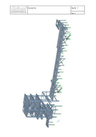
Scope of this report is the check the structural support of the tower and furnace for _________. The structure
in located indoor and is composed by 2 body connected: the tower and the furnace.
The structure of tower is height 25,3 m have 5 plans of dimension pair to 14,5 x 8,55 m.
In longitudinal direction there are braces frames at all plans row A and braces frame at 4th-5th planes rows B-
C.
In cross direction there are braced frames at 4th-5th planes rows 5-8.
The structure of furnace is height 5,3 m with plans dimension pair to 65 x 10,7 m.
In longitudinal direction there are braced frames at rows 5-8.
In cross direction there are moment resisting frame connections.
2 APPLICABLE CODES
Eurocode 3 – UNI ENV 1993-1-1 “Design of steel structures part 1-1: General rules and rules for buildings”
Actions on structures:
Weight of equipment, strip tension, dynamic load of the fans have been received from ______ technical
department.
3 MATERIALS
Plates and shapes: S275 JR – EN 10025
Yield stress 275 N/mm²
Tensile stress 430 N/mm²
Bolted connections according to EN20898. Bolts class 8.8
7. Document No. Pag./Pg 7
Rev. 0
4 LOADS DEFINITION
In the calculation the following load cases have been included:
TABLE: Load Pattern Definitions
LoadPat DesignType SelfWtMult
Text Text Unitless
DEAD DEAD 1,2
LIVE LIVE 0
EQPT_SL DEAD 0
EQPT_DY_X OTHER 0
EQPT_DY_Y OTHER 0
MINISPANGLE DEAD 0
COIL OTHER 0
CRANE DEAD 0
MANUT OTHER 0
COIL WEIGHT DEAD 0
LATERAL LOAD OTHER 0
CONTENT LIVE 0
WFU OTHER 0
WFY OTHER 0
DEAD
Is the dead load. This case includes the self weight of the structure, the weight of the grating and hand rails
LIVE
Is the live load on the service plan, walkways, stairs and roof
EQPT_ST
Is the self-weight of the installed equipment.
EQPT_DY_(X-Y)
Is the dynamic load of the strip supports.
MINISPANGLE
It is the self-weight of minispangle.
It is a moving load present in operating condition and it is shows in chapter [9]
COIL
Is the self-weight of coil applied on frame supports.
MOVING LOAD (CRANE)
Moving load are present in maintenance condition. They are show in chapter [9].
MANUT
Is the live load due to maintenance of structure
8. Document No. Pag./Pg 8
Rev. 0
COIL WEIGTH
Is the weight of coil in first application
LATERAL LOAD
Is the dynamic effect of railway. It is show in chapter [9]
CONTENT
It is the weight of content of silos present to height +15,5
WINCH FRAME (WFU)
It’s the static effect of winch frame machine presents at the last floor [ref. n.19 tab.13].
WINCH FRAME (WFY)
It’s the dynamic effect of winch frame machine presents at the last floor [ref. n.19 tab.13].
9. Document No. Pag./Pg 9
Rev. 0
The following analysis cases have been included in the calculation.
TABLE: Load Case Definitions
Case Type InitialCond ModalCase DesignType
Text Text Text Text Text
DEAD LinStatic p-delta DEAD
MODAL LinModal Zero OTHER
LIVE LinStatic p-delta LIVE
EQPT_SL LinStatic p-delta DEAD
EQPT_DY_X LinStatic p-delta OTHER
EQPT_DY_Y LinStatic p-delta OTHER
COIL LinStatic p-delta OTHER
POT CRANE LinMoving Zero
VEHICLE
LIVE
MANUT RAILS LinMoving Zero
VEHICLE
LIVE
INGOT RAIL LinMoving Zero
VEHICLE
LIVE
MINISPANGLE LinStatic Zero DEAD
CRANE LinStatic p-delta DEAD
COIL WEIGHT LinStatic p-delta DEAD
SBANDAMENTO LinStatic p-delta OTHER
MANUT LinStatic p-delta OTHER
p-delta NonStatic Zero DEAD
QUAKE_X LinRespSpec RITZ QUAKE
QUAKE_Y LinRespSpec RITZ QUAKE
CONTENT LinStatic Zero LIVE
RITZ LinModal Zero QUAKE
WFU LinStatic Zero OTHER
WFY LinStatic Zero OTHER
10. Document No. Pag./Pg 10
Rev. 0
With the following further information:
P-Delta Analysis
All analysis cases have been solved in the following way:
Similarly for the other cases.
11. Document No. Pag./Pg 11
Rev. 0
4.1 DEAD LOAD (DEAD)
All the self weight of he members have been multiplied by 1.2 to take in account the weight of plates, bolts,,,
The self weight of the covering plates is: 0.45 kN/m²
The self weight of the handrails has been judged negligible.
4.2 LIVE LOAD (LIVE)
The design live load is 4.0 kN/m². This load has been applied only in the areas equipment free.
4.3 EQUIPMENT (EQPT_SL,EQPT_DX_X,EQPT_DY_Y)
The equipment is formed by the elements of the furnace and other various equipment.
In particular the EQPT_ST is due to the equipment of rolling, coil and other equipment.
The EQPT_DX_X-EQPT_DY_Y are due to the dynamic load of fan coil.
The loads are taken by _________________ report in the following.
13. Document No. Pag./Pg 13
Rev. 0
4.4 QUAKE_X-Y
For the definition of the seismic force it is used Seismic design code for Dubai (2013) with input data
Ssd/g=0,24; S1d/g=0,16.
14. Document No. Pag./Pg 14
Rev. 0
4.5 OPERATING LOAD (COIL)
From the Tension Diagram produced by Danieli, the strip tension is 50,0 kN.
IMMAGINE IS NOT AVAILABLE
15. Document No. Pag./Pg 15
Rev. 0
In the hot bridle area we have to consider the effects of the tension in the strip
Z
X
Angles of the strip with the horizontal
F1 F2 F3 F4 F5 F6 F7 F8 F9 F10
α 0 40 -40 -56 56 90 -90 180 0 -90
F11 F12 F13 F14 F15 F16 F17 F18 F19 F20
α 90 90 -90 180 0 -90 90 180 0 -90
Now we define the resultant forces on the roll axis.
The tension load on the strip is 50 kN
Roll 1 2 3 4 5 6 7 8 9 10
Fx [kN] 68,04 27,6 [-] -50 -50 100 -50 -50 -50 50
Fz [kN] 71,11 91,94 [-] -50 50 0 50 50 50 -50
Moments:
From roll 1. Eccentricity: 0.85 m My = 68,04x0.85 = 58,3 kNm
From roll 2 Eccentricity: 1.15 m My = -91,94x1.15 = 105,8 kNm
From roll 4 Eccentricity: 1.65 m My = -50x1.65 = -82,5 kNm
From roll 5 Eccentricity: 1.65 m My = 50x1.65 = 82,5 kNm
16. Document No. Pag./Pg 16
Rev. 0
From roll 7 Eccentricity: 2.5 m My = -50x2,5 = -125 kNm
From roll 8 Eccentricity: 2.5 m My = 50x2,5 = 125 kNm
From roll 9 Eccentricity: 1.25 m My = -50x1.25 = -63 kNm
From roll 10 Eccentricity: 1.25 m My = 50x1.25 = 63 kNm
The maintenance load is the suspended loads of the monorails (15-30-20 kN).
The railway present in rows B1-C1 is used by minispangle (tag load 440 kN) active in operating condition
and by crane (tag load 270 kN) active in maintenance condition.
Conservatively this load is applied as moving load in all support points of the monorails/railway.
17. Document No. Pag./Pg 17
Rev. 0
4.6 OPERX / OPERY
Below the furnace level there are the support of the strip.
These support are sustained by longitudinal beams between the main columns.
4.7 CONTENT (CONTENT)
It is the weight of content of silos present to height +15,5 pair to 18,4kN
4.8 MOVING LOAD (POT CRANE, MANUT RAILS, INGOT RAIL, MINISPANGLE )
Moving load are present in operating/maintenance condition. They are show in chapter [9].