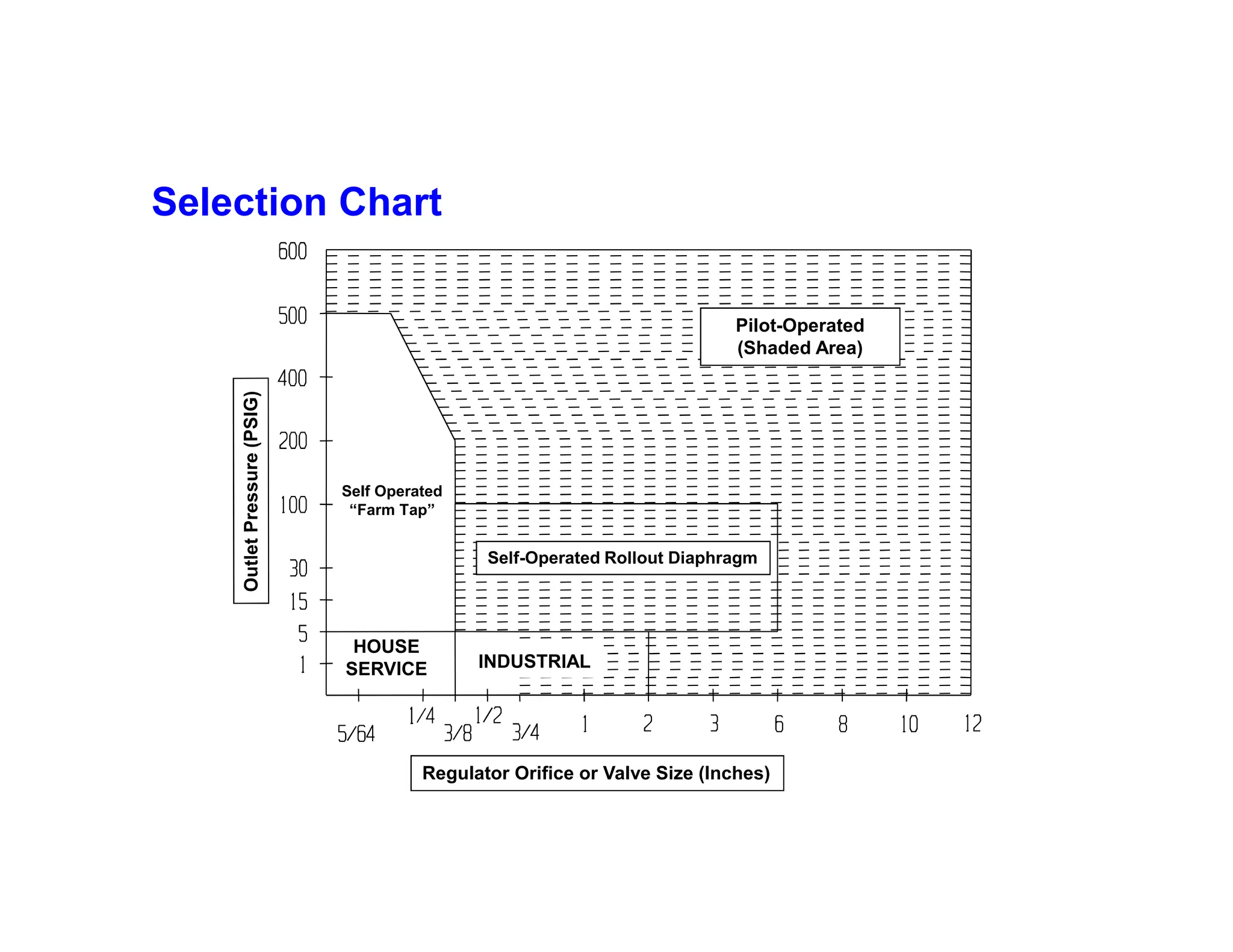
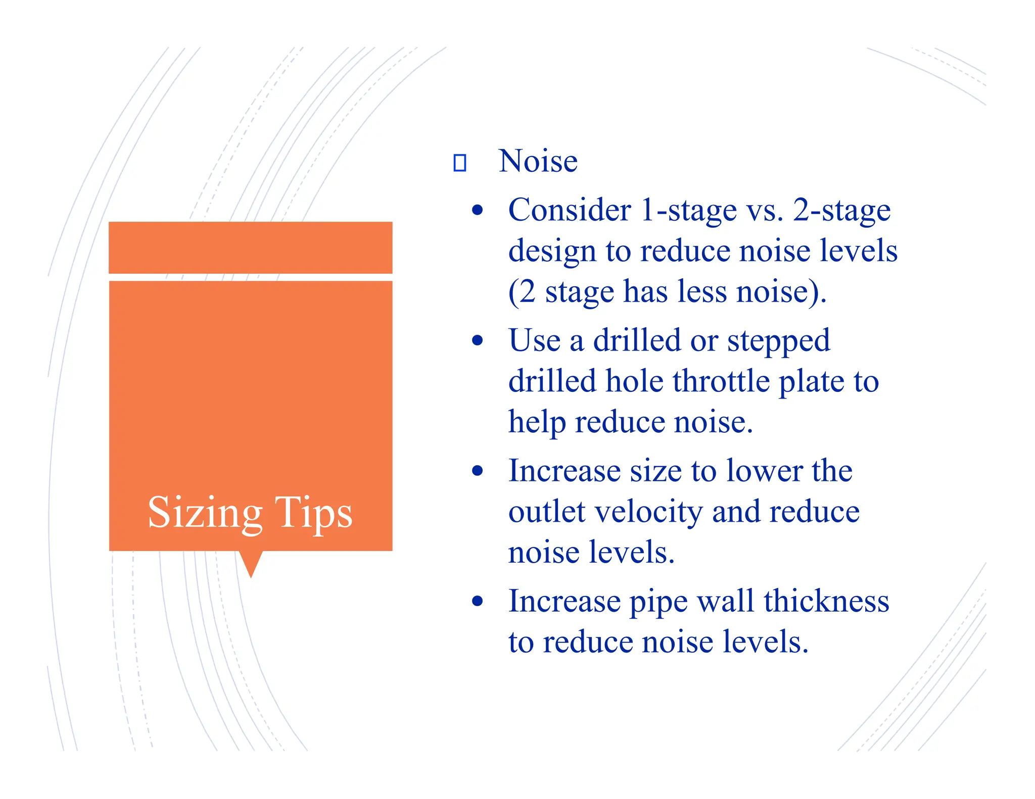
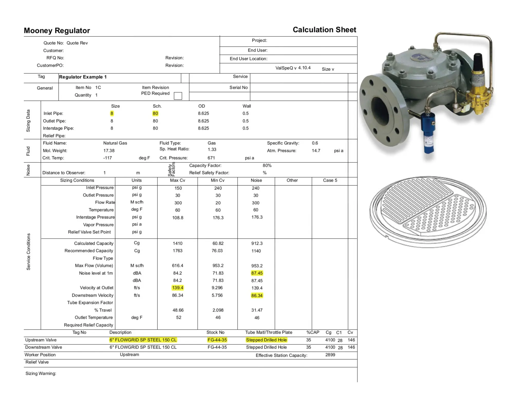
Regulator and Control Valve Sizing
By
Hugh Masterson and Jim Mueller
Master Controls
March 13, 2019 2
What is a regulator?
A Regulator is a device that controls the flow of gas from a
higher pressure system to a lower pressure system while
attempting to maintain a constant pressure or flow.
HIGHER MAOP LOWER MAOP
Regulator Selection
o Select the correct regulator for the
application considering the following:
• Speed of response, i.e., boiler fuel
• Differential pressure
• Turndown = Max flow/min flow
• Noise
• Accuracy
• Self Operated
• Pilot Operated
• Control Valve
Selection Chart
Regulator Orifice or Valve Size (Inches)
Pilot-Operated
(Shaded Area)
Self Operated
“Farm Tap”
HOUSE
SERVICE INDUSTRIAL
Self-Operated Rollout Diaphragm
Self Operated Pressure Reducing Regulator
Loading Element
Measuring Element
Restrictive Element
10 psig
10 lbs force
High
Pressure
Low
Pressure
100psig
100psig
Sizing Tips
 Factors to Consider
• Filter - pilot supply – always.
• Filter - entire station?
• Overpressure protection?
• Hydrates and/or freezing (Joule-
Thompson effect)? Adding a pilot gas
heater?
• Throttle plate selection (capacity and
type to prevent diaphragm erosion in
high pressure cuts).
• Exit and downstream gas velocity.
Larger regulators and downstream pipe
diameters results in lower velocity.
Sizing Tips
 Factors to Consider
• Pipeline turbulence caused by other
equipment (elbows, tee’s, valves, etc.)
that can affect sense lines.
• Sense lines should be 8 to 10 pipe
diameters down stream, 4 diameters
upstream of a tee or elbow.
• Diaphragm selection (chemical
compatibility, differential pressure
rating, temperature, resistance to
abrasion).
• Solution versus cost assessment
• Single regulator or monitor regulator
set?
Sizing Tips
 Noise
• Consider 1-stage vs. 2-stage
design to reduce noise levels
(2 stage has less noise).
• Use a drilled or stepped
drilled hole throttle plate to
help reduce noise.
• Increase size to lower the
outlet velocity and reduce
noise levels.
• Increase pipe wall thickness
to reduce noise levels.
Sizing Tips
 Capacity
– Optimal design should not
exceed 75% - 80% of maximum
capacity (capacity factor of 75%
- 80%) .
– Better to oversize than
undersize.
– Rangeability (turn down)
» 50:1 – Slotted throttle plate
» 100:1 – Slotted throttle plate
» Greater than 100:1 – Stepped
drilled hole throttle plate
Sizing Tips
 Design Considerations
o Minimum pressure
differential :
See Differential Chart
o Maximum pressure
differential :
800 psid (1000 psid for 1”)
Mooney Flowgrid Regulator
Pressure Reducing Application - Standby Monitor
Confidential
Sizing Conditions
o Maximum ∆P
 ANSI Class, Regulator Specification
 Maximum control point, % Open
 Minimum control point, % Open
 For Mooney regulators use
stepped drilled hole throttle
plates for Cg’s less than 4 to 5%
of the regulators capacity
o Max Downstream Gas Velocity
 Above ground ~100 fps
 Below ground ~200 fps
o Max Valve Exit Velocity
 0.3 X Mach ~230 fps
o Control Valve Operating Range
 Standard Becker; 10 - 93% open
o Max. Cv Condition
 Max. Flow (Q)
 Min. Inlet Pressure (P1)
 Max. Outlet Pressure (P2)
 Max. Temperature (T)
o Min. Cv Condition
 Min. Flow (Q)
 Max. Inlet Pressure (P1)
 Min. Outlet Pressure (P1)
 Min. Temperature (T)
o Max. Noise Condition
 Max. Flow (Q)
 Max. Inlet Pressure (P1)
 Min. Outlet Pressure (P2)
 Max. Temperature (T)
Universal Gas Sizing Equation
 
1
1
1
3417
GT
520
Q
P
P
C
Sin
P
Cg






Cg = gas sizing coefficient
Cv = liquid sizing coefficient
C1 = Cg/Cv
G = gas specific gravity (air = 1.0)
P1 = inlet pressure, psia
P2 = outlet pressure, psia
ΔP = pressure drop P1 – P2, psi
T = flow temperature, °R(460 + °F)
Follow these instructions.
Select the ValSpeQ vX.XX link above and save to a location on your hard drive.
DO NOT CLICK THE RUN BUTTON FROM THE DOWNLOAD DIALOG. CLICK ONLY THE SAVE BUTTON.
RUN ALL INSTALLS BY USING THE RIGHT CLICK “RUN AS ADMINISTRATOR” METHOD
After successful and complete save to the file system…
¨ If this edition has never been installed on the pc before, you will get prompted for registration information
below
o If prompted for Product Key, enter 60015410
o If prompted for Install key, leave this area blank, and hit next
o Enter all registration information
o If prompted to save registration file to desktop, do so.
o If prompted to e-mail registration in, do so, copy valspeq.support@ge.com on the resulting e-mail
that gets created by the installer.
o Hit back button and wait for the install key from me., if you hit finish, you will have to rerun the
installation when you receive the install key.
o When you receive the install key, enter the install key code, and hit next, the installation will
continue.
¨ Otherwise the install will not prompt and you can proceed normally.
Regulator
Sizing
Examples
Regulator Sizing Example 1
Max Cv Case Min Cv Case Noise Case
Flow Rate (Q) MSCFH 300 20 300
Upstream Pressure (P1) 150 psig 240 psig 240 psig
Downstream Pressure (P2) 30 psig 30 psig 30 psig
Gas Temperature deg F 60 60 60
85 - 90 dBA Noise Requirement
Flow Rate (Q) 20 – 300 MSCFH
Upstream Pressure Range P(1) 150 – 240 PSIG
Downstream Pressure P(2) 30
Inlet Gas Temp 60 deg F
Regulator Sizing Example 2
Max Cv Case Min Cv Case Noise Case
Flow Rate (Q) MSCFH 30 4 30
Upstream Pressure (P1) 700 psig 850 psig 850 psig
Downstream Pressure (P2) 150 psig 150 psig 150 psig
Gas Temperature deg F 60 60 60
85 - 90 dBA Noise Requirement
Flow Rate (Q) 4 – 30 MSCFH
Upstream Pressure Range P(1) 700 – 850 PSIG
Downstream Pressure P(2) 150
Inlet Gas Temp 60 deg F
Joule-Thomson Effect
When a highly compressed gas is allowed to escape / expand through a small opening, it absorbs
a great deal of energy from its surroundings, causing the surrounding temperature to drop. This
is the basis of refrigeration.
As a rule of thumb gas temperatures will drop ~ 7 Degrees F for every 100 psig in pressure drop.
Joule-Thomson Effect
Pilot Gas Heating
Pilot Gas Heating
Control Valve
Sizing
Examples
Control Valve Sizing Example 1
Max Cv Case Min Cv Case Noise Case
Flow Rate (Q) MMSCFD 300 25 300
Upstream Pressure (P1) 950 psig 1050 psig 1050 psig
Downstream Pressure (P2) 935 psig 935 psig 935 psig
Gas Temperature deg F 60 60 60
85 - 90 dBA Noise Requirement
Flow Rate (Q) 25 – 300 MMSCFD
Upstream Pressure Range P(1) 950 – 1050 PSIG
Downstream Pressure P(2) 935
Inlet Gas Temp 60 deg F
Control Valve Sizing Example 2
Max Cv Case Min Cv Case Noise Case
Flow Rate (Q) MMSCFD 440 50 440
Upstream Pressure (P1) 900 psig 1200 psig 1200 psig
Downstream Pressure (P2) 850 psig 850 psig 850 psig
Gas Temperature deg F 60 60 60
85 - 90 dBA Noise Requirement
Flow Rate (Q) 50 – 440 MMSCFD
Upstream Pressure Range P(1) 900 – 1200 PSIG
Downstream Pressure P(2) 850
Inlet Gas Temp 60 deg F
Filters and Filter/Dryers
Cold Gas Increases the potential for liquid
dropout
Joule-Thomson Effect
When a highly compressed gas is allowed to escape / expand through a small opening, it absorbs
a great deal of energy from its surroundings, causing the surrounding temperature to drop. This
is the basis of refrigeration.
As a rule of thumb gas temperatures will drop ~ 7 Degrees F for every 100 psig in pressure drop.
Filtering
Vertical Pipeline Heater
Horizontal Pipeline Heater

Regulator-and-Control-Valve-Sizing (2).pdf

  • 1.
    Regulator and ControlValve Sizing By Hugh Masterson and Jim Mueller Master Controls
  • 2.
  • 4.
    What is aregulator? A Regulator is a device that controls the flow of gas from a higher pressure system to a lower pressure system while attempting to maintain a constant pressure or flow. HIGHER MAOP LOWER MAOP
  • 5.
    Regulator Selection o Selectthe correct regulator for the application considering the following: • Speed of response, i.e., boiler fuel • Differential pressure • Turndown = Max flow/min flow • Noise • Accuracy • Self Operated • Pilot Operated • Control Valve
  • 6.
    Selection Chart Regulator Orificeor Valve Size (Inches) Pilot-Operated (Shaded Area) Self Operated “Farm Tap” HOUSE SERVICE INDUSTRIAL Self-Operated Rollout Diaphragm
  • 7.
    Self Operated PressureReducing Regulator Loading Element Measuring Element Restrictive Element 10 psig 10 lbs force High Pressure Low Pressure 100psig 100psig
  • 11.
    Sizing Tips  Factorsto Consider • Filter - pilot supply – always. • Filter - entire station? • Overpressure protection? • Hydrates and/or freezing (Joule- Thompson effect)? Adding a pilot gas heater? • Throttle plate selection (capacity and type to prevent diaphragm erosion in high pressure cuts). • Exit and downstream gas velocity. Larger regulators and downstream pipe diameters results in lower velocity.
  • 12.
    Sizing Tips  Factorsto Consider • Pipeline turbulence caused by other equipment (elbows, tee’s, valves, etc.) that can affect sense lines. • Sense lines should be 8 to 10 pipe diameters down stream, 4 diameters upstream of a tee or elbow. • Diaphragm selection (chemical compatibility, differential pressure rating, temperature, resistance to abrasion). • Solution versus cost assessment • Single regulator or monitor regulator set?
  • 13.
    Sizing Tips  Noise •Consider 1-stage vs. 2-stage design to reduce noise levels (2 stage has less noise). • Use a drilled or stepped drilled hole throttle plate to help reduce noise. • Increase size to lower the outlet velocity and reduce noise levels. • Increase pipe wall thickness to reduce noise levels.
  • 14.
    Sizing Tips  Capacity –Optimal design should not exceed 75% - 80% of maximum capacity (capacity factor of 75% - 80%) . – Better to oversize than undersize. – Rangeability (turn down) » 50:1 – Slotted throttle plate » 100:1 – Slotted throttle plate » Greater than 100:1 – Stepped drilled hole throttle plate
  • 15.
    Sizing Tips  DesignConsiderations o Minimum pressure differential : See Differential Chart o Maximum pressure differential : 800 psid (1000 psid for 1”)
  • 16.
  • 17.
    Pressure Reducing Application- Standby Monitor Confidential
  • 18.
    Sizing Conditions o Maximum∆P  ANSI Class, Regulator Specification  Maximum control point, % Open  Minimum control point, % Open  For Mooney regulators use stepped drilled hole throttle plates for Cg’s less than 4 to 5% of the regulators capacity o Max Downstream Gas Velocity  Above ground ~100 fps  Below ground ~200 fps o Max Valve Exit Velocity  0.3 X Mach ~230 fps o Control Valve Operating Range  Standard Becker; 10 - 93% open o Max. Cv Condition  Max. Flow (Q)  Min. Inlet Pressure (P1)  Max. Outlet Pressure (P2)  Max. Temperature (T) o Min. Cv Condition  Min. Flow (Q)  Max. Inlet Pressure (P1)  Min. Outlet Pressure (P1)  Min. Temperature (T) o Max. Noise Condition  Max. Flow (Q)  Max. Inlet Pressure (P1)  Min. Outlet Pressure (P2)  Max. Temperature (T)
  • 19.
    Universal Gas SizingEquation   1 1 1 3417 GT 520 Q P P C Sin P Cg       Cg = gas sizing coefficient Cv = liquid sizing coefficient C1 = Cg/Cv G = gas specific gravity (air = 1.0) P1 = inlet pressure, psia P2 = outlet pressure, psia ΔP = pressure drop P1 – P2, psi T = flow temperature, °R(460 + °F)
  • 22.
    Follow these instructions. Selectthe ValSpeQ vX.XX link above and save to a location on your hard drive. DO NOT CLICK THE RUN BUTTON FROM THE DOWNLOAD DIALOG. CLICK ONLY THE SAVE BUTTON. RUN ALL INSTALLS BY USING THE RIGHT CLICK “RUN AS ADMINISTRATOR” METHOD After successful and complete save to the file system… ¨ If this edition has never been installed on the pc before, you will get prompted for registration information below o If prompted for Product Key, enter 60015410 o If prompted for Install key, leave this area blank, and hit next o Enter all registration information o If prompted to save registration file to desktop, do so. o If prompted to e-mail registration in, do so, copy valspeq.support@ge.com on the resulting e-mail that gets created by the installer. o Hit back button and wait for the install key from me., if you hit finish, you will have to rerun the installation when you receive the install key. o When you receive the install key, enter the install key code, and hit next, the installation will continue. ¨ Otherwise the install will not prompt and you can proceed normally.
  • 23.
  • 24.
    Regulator Sizing Example1 Max Cv Case Min Cv Case Noise Case Flow Rate (Q) MSCFH 300 20 300 Upstream Pressure (P1) 150 psig 240 psig 240 psig Downstream Pressure (P2) 30 psig 30 psig 30 psig Gas Temperature deg F 60 60 60 85 - 90 dBA Noise Requirement Flow Rate (Q) 20 – 300 MSCFH Upstream Pressure Range P(1) 150 – 240 PSIG Downstream Pressure P(2) 30 Inlet Gas Temp 60 deg F
  • 29.
    Regulator Sizing Example2 Max Cv Case Min Cv Case Noise Case Flow Rate (Q) MSCFH 30 4 30 Upstream Pressure (P1) 700 psig 850 psig 850 psig Downstream Pressure (P2) 150 psig 150 psig 150 psig Gas Temperature deg F 60 60 60 85 - 90 dBA Noise Requirement Flow Rate (Q) 4 – 30 MSCFH Upstream Pressure Range P(1) 700 – 850 PSIG Downstream Pressure P(2) 150 Inlet Gas Temp 60 deg F
  • 31.
    Joule-Thomson Effect When ahighly compressed gas is allowed to escape / expand through a small opening, it absorbs a great deal of energy from its surroundings, causing the surrounding temperature to drop. This is the basis of refrigeration. As a rule of thumb gas temperatures will drop ~ 7 Degrees F for every 100 psig in pressure drop.
  • 32.
  • 33.
  • 34.
  • 35.
  • 36.
    Control Valve SizingExample 1 Max Cv Case Min Cv Case Noise Case Flow Rate (Q) MMSCFD 300 25 300 Upstream Pressure (P1) 950 psig 1050 psig 1050 psig Downstream Pressure (P2) 935 psig 935 psig 935 psig Gas Temperature deg F 60 60 60 85 - 90 dBA Noise Requirement Flow Rate (Q) 25 – 300 MMSCFD Upstream Pressure Range P(1) 950 – 1050 PSIG Downstream Pressure P(2) 935 Inlet Gas Temp 60 deg F
  • 40.
    Control Valve SizingExample 2 Max Cv Case Min Cv Case Noise Case Flow Rate (Q) MMSCFD 440 50 440 Upstream Pressure (P1) 900 psig 1200 psig 1200 psig Downstream Pressure (P2) 850 psig 850 psig 850 psig Gas Temperature deg F 60 60 60 85 - 90 dBA Noise Requirement Flow Rate (Q) 50 – 440 MMSCFD Upstream Pressure Range P(1) 900 – 1200 PSIG Downstream Pressure P(2) 850 Inlet Gas Temp 60 deg F
  • 44.
  • 45.
    Cold Gas Increasesthe potential for liquid dropout
  • 46.
    Joule-Thomson Effect When ahighly compressed gas is allowed to escape / expand through a small opening, it absorbs a great deal of energy from its surroundings, causing the surrounding temperature to drop. This is the basis of refrigeration. As a rule of thumb gas temperatures will drop ~ 7 Degrees F for every 100 psig in pressure drop.
  • 47.
  • 49.
  • 50.