Downloaded 20 times
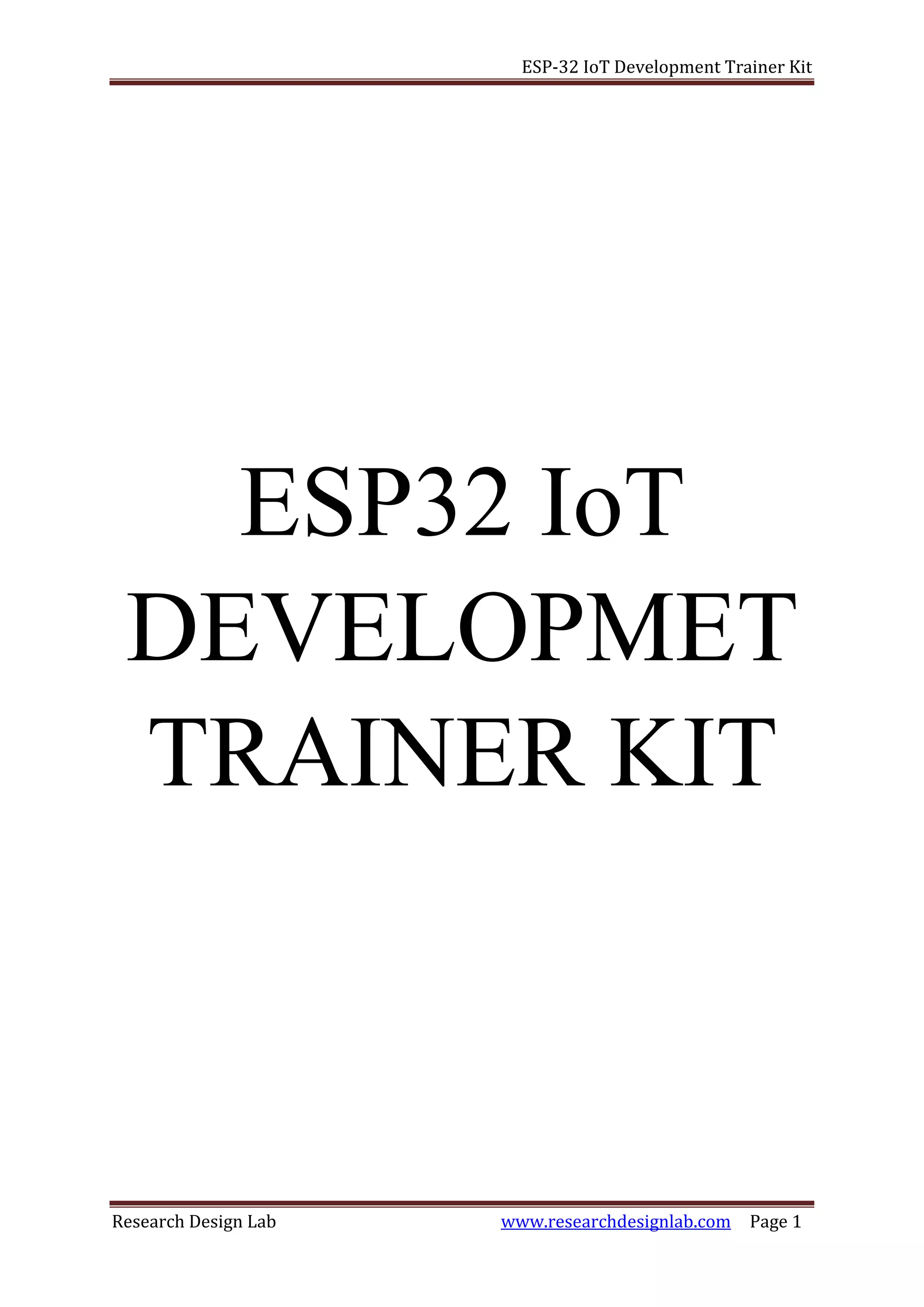
![ESP-32 IoT Development Trainer Kit
Research Design Lab www.researchdesignlab.com Page 16
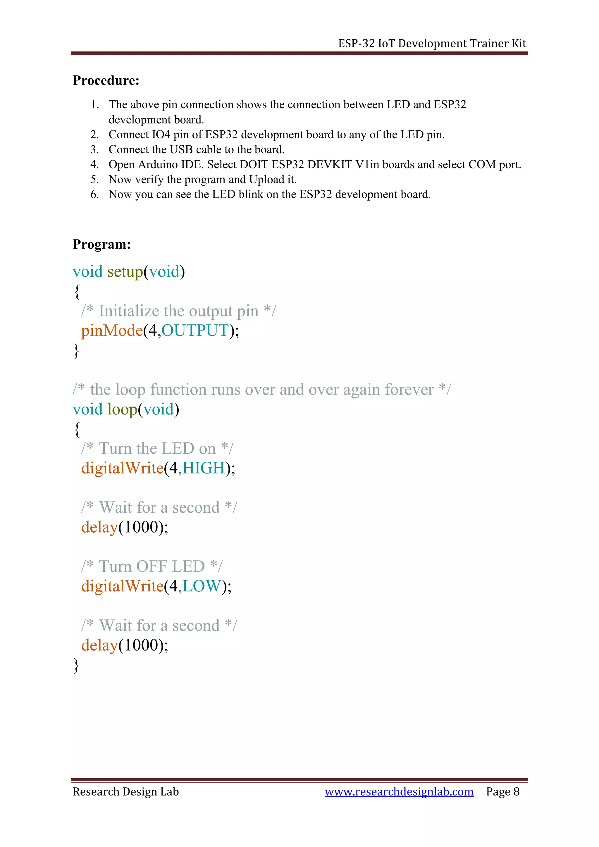
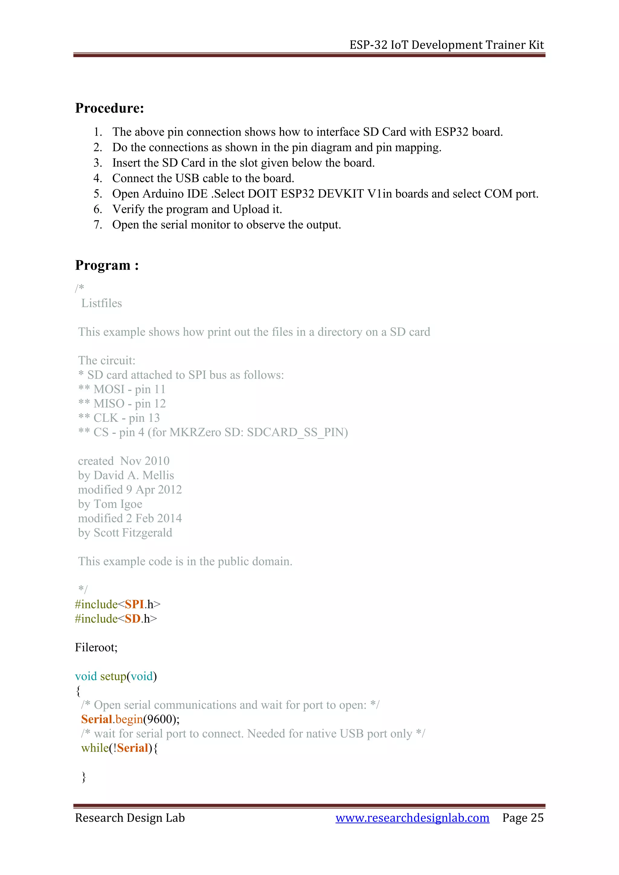
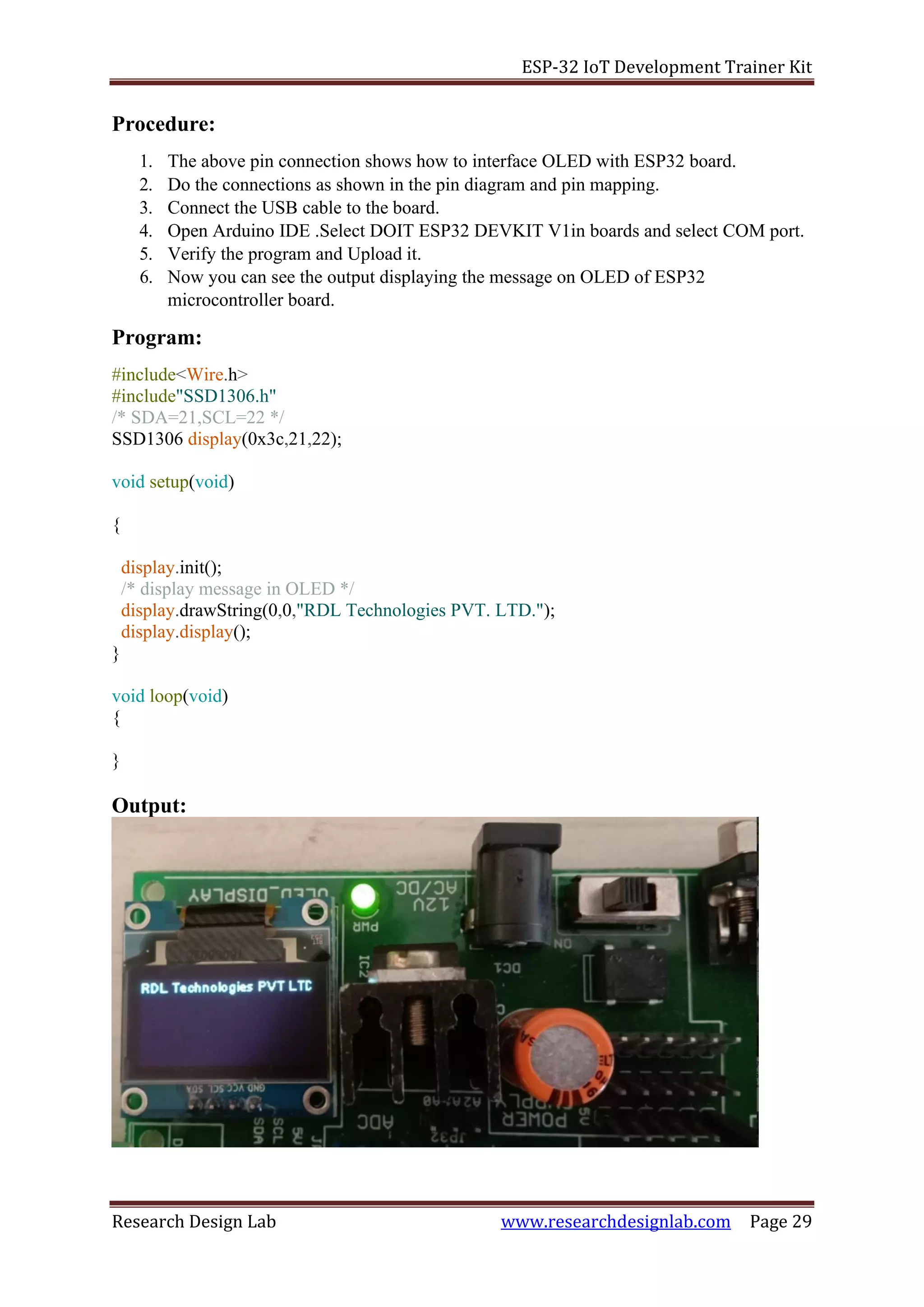
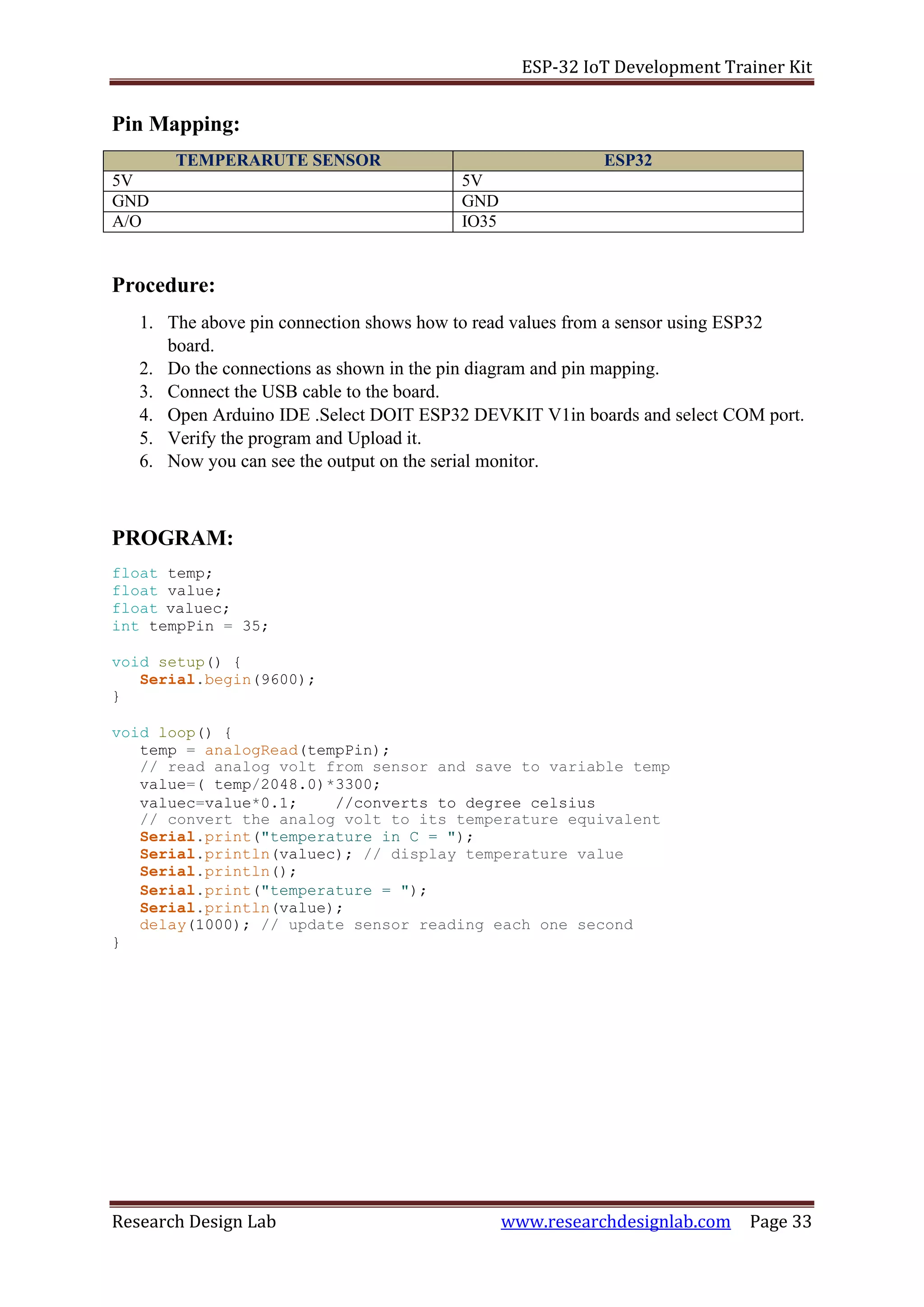
Procedure:
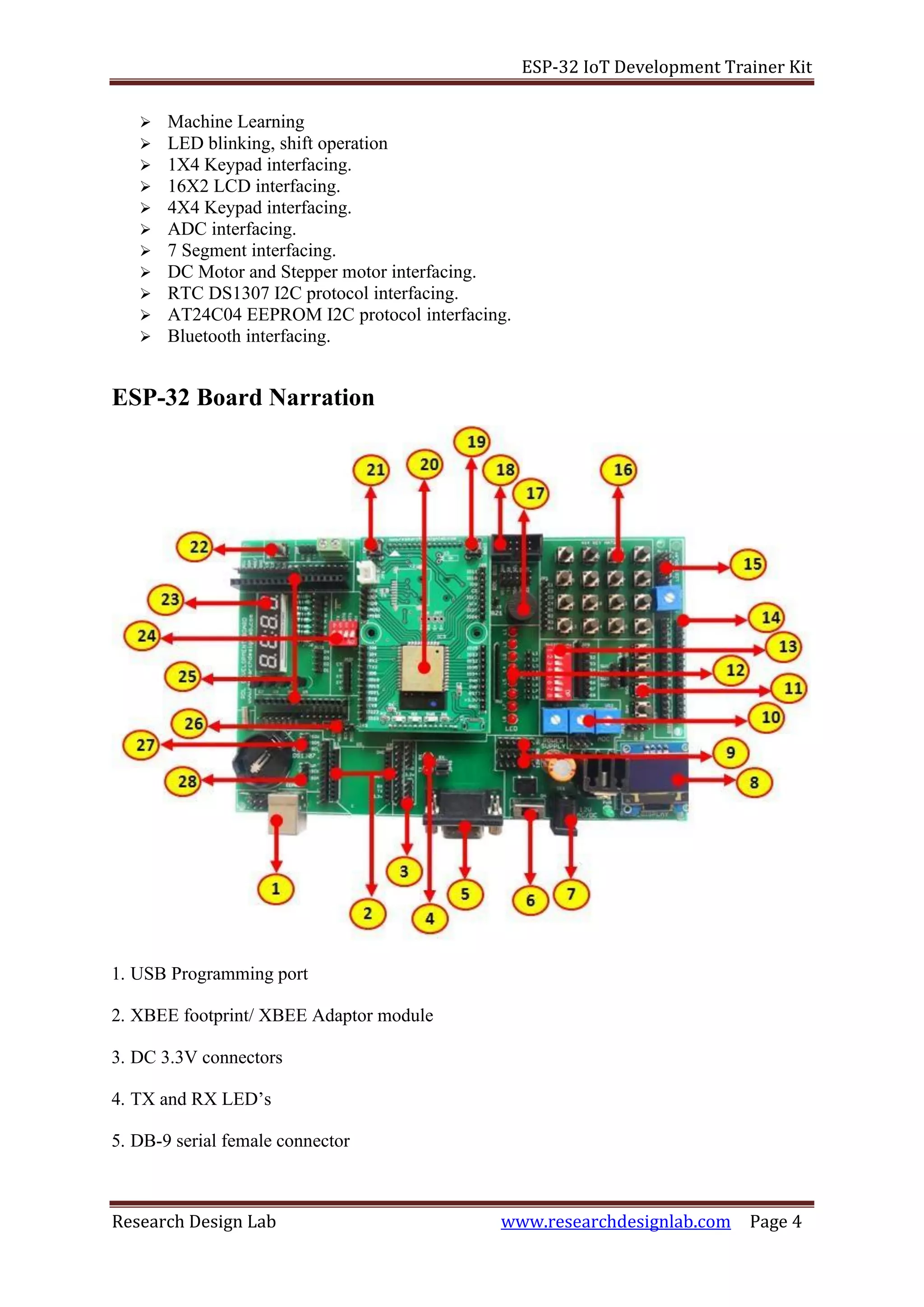
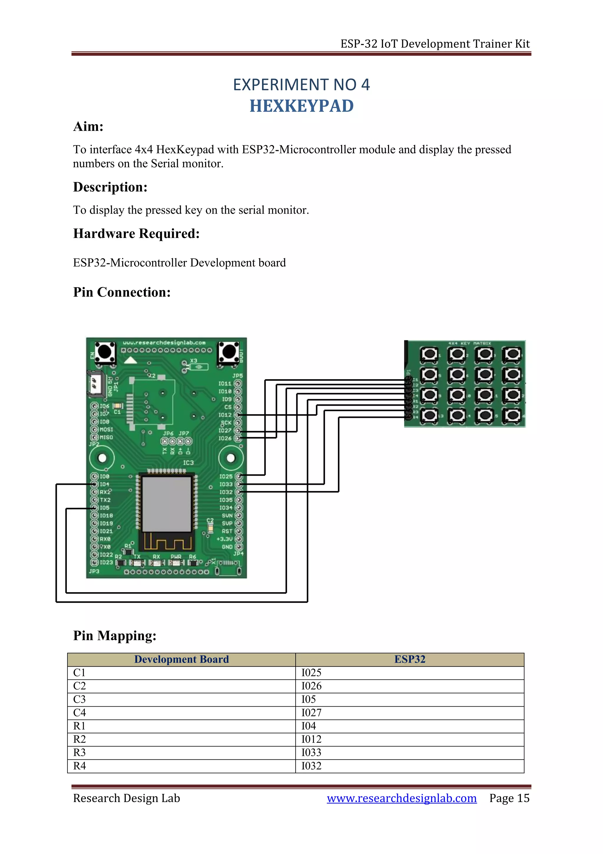
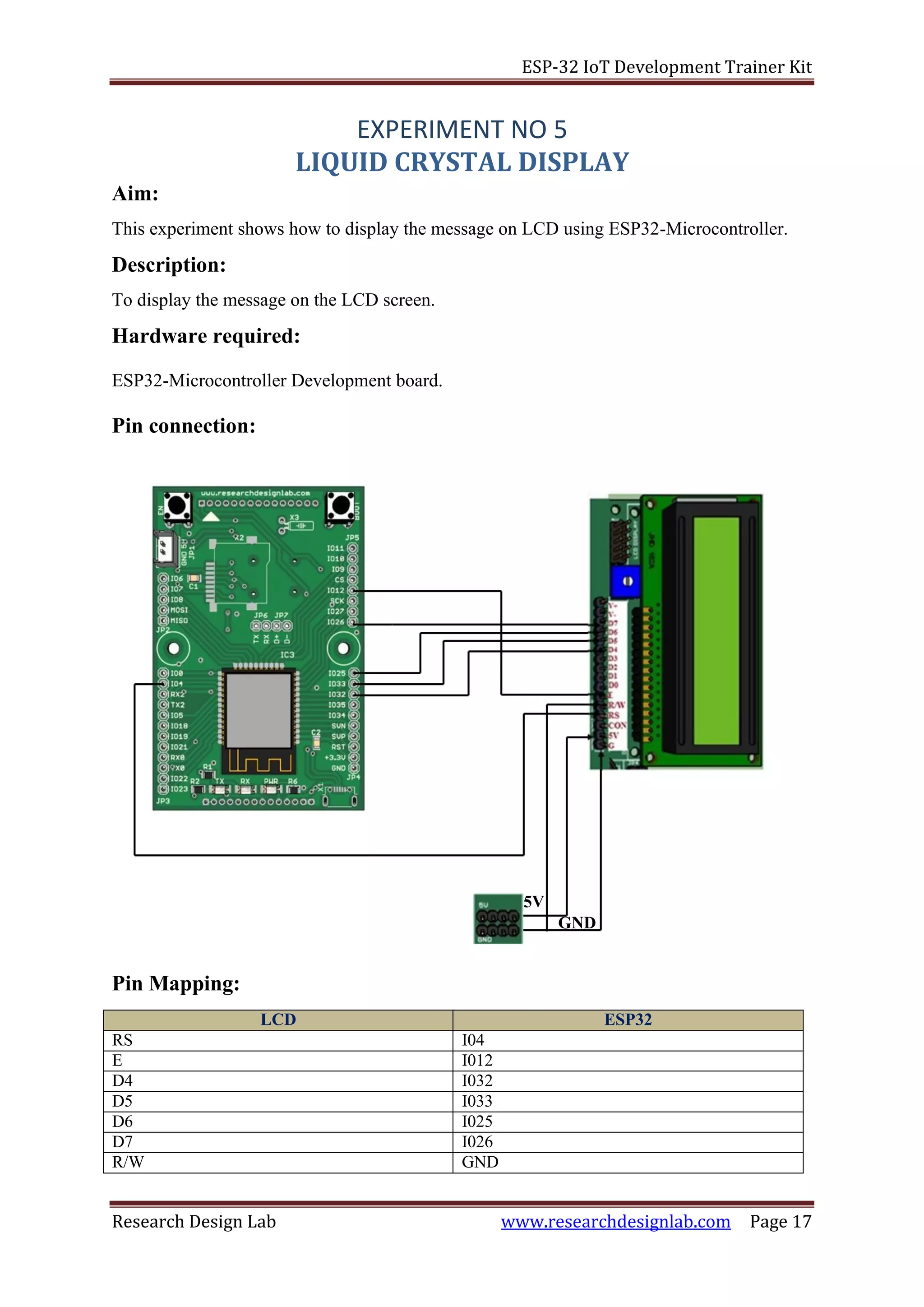
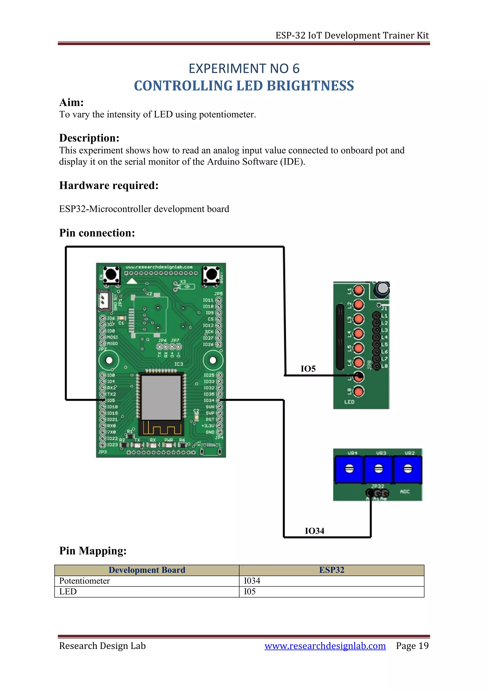
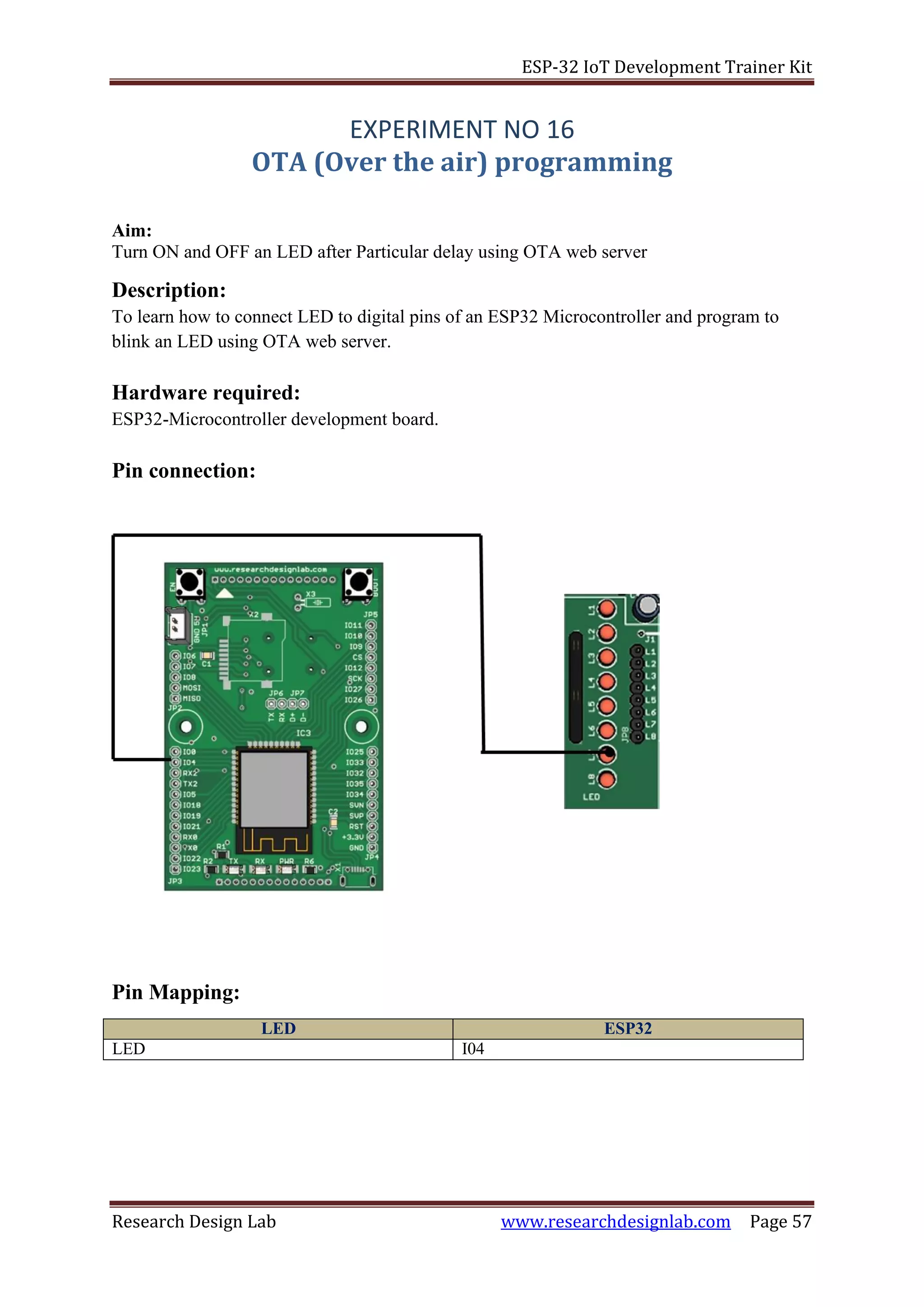
1. The above pin connection shows how to interface Hexkeypad with ESP32 board.
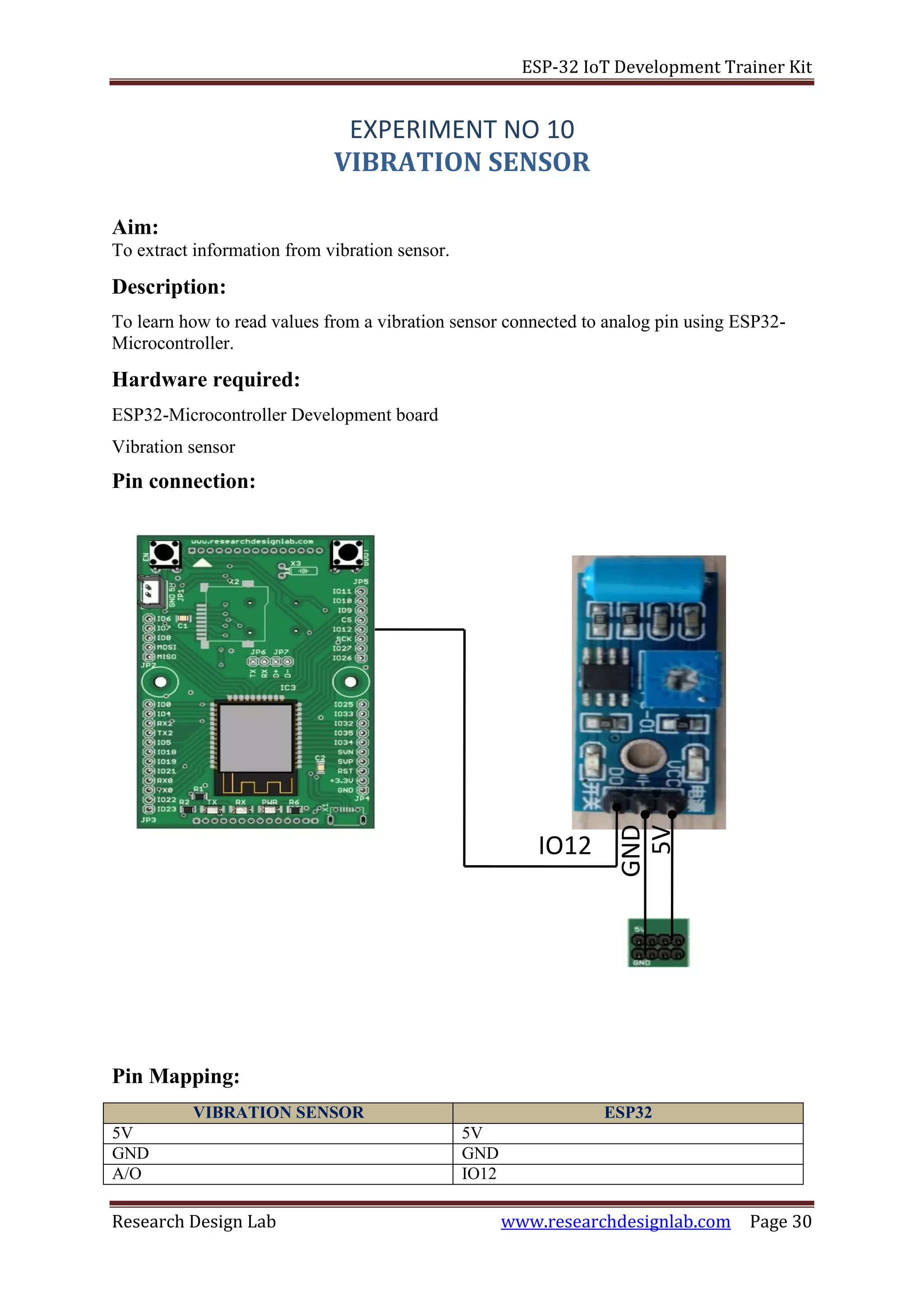
2. Do the connections as shown in the pin diagram and pin mapping.
3. Connect the USB cable to the board.
4. Open Arduino IDE .Select DOIT ESP32 DEVKIT V1in boards and select COM port.
5. Now verify the program and Upload it.
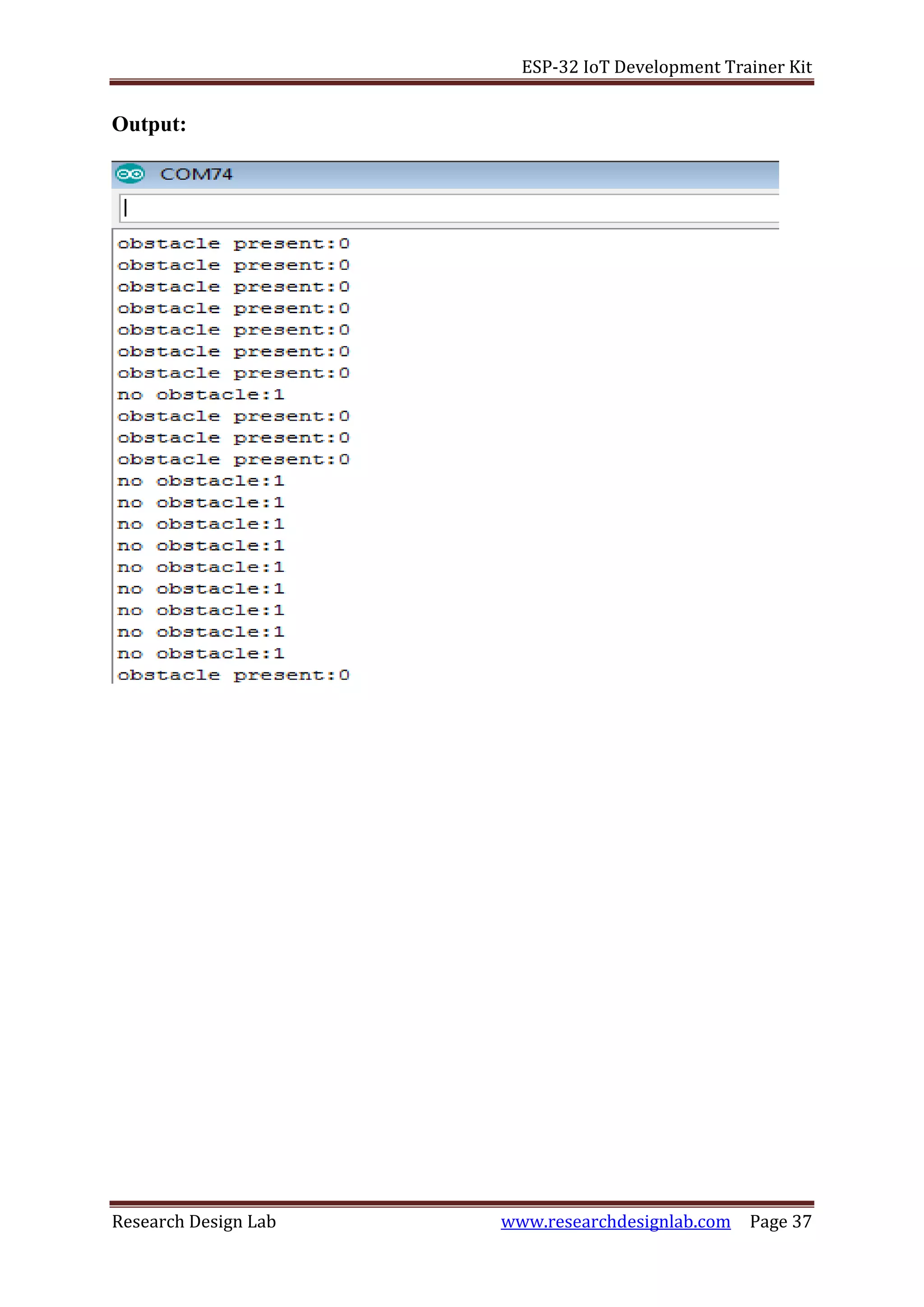
6. After uploading is done open serial monitor to observe the output.
7. For a particular switch the same number displays on our serial monitor.
Program:
/* Include the Keypad header file */
#include<Keypad.h>
/* four rows */
const byte ROWS=4;
/* four columns */
constbyteCOLS=4;
/* define the symbols on the buttons of the keypads */
charhexaKeys[ROWS][COLS]={
{'0','1','2','3'},
{'4','5','6','7'},
{'8','9','A','B'},
{'C','D','E','F'}
};
/* connect to the row pinouts of the keypad */
byterowPins[ROWS]={4,12,33,32};
/* connect to the column pinouts of the keypad */
bytecolPins[COLS]={25,26,5,27};
/* initialize an instance of class NewKeypad */
KeypadcustomKeypad=Keypad(makeKeymap(hexaKeys),rowPins,colPins,ROWS,COLS);
/* counter intialization */
intcounter=0;
void setup(void)
{
Serial.begin(9600);
}
void loop(void)
{
/* Key pressed is stored in customkey */
charcustomKey=customKeypad.getKey();
if(customKey)
{
/* Key pressed is stored in customkey */
Serial.println(customKey);
}
}](https://image.slidesharecdn.com/rdlesp32developmentboardtrainerkit-190829074544/75/Rdl-esp32-development-board-trainer-kit-16-2048.jpg)
![ESP-32 IoT Development Trainer Kit
Research Design Lab www.researchdesignlab.com Page 43
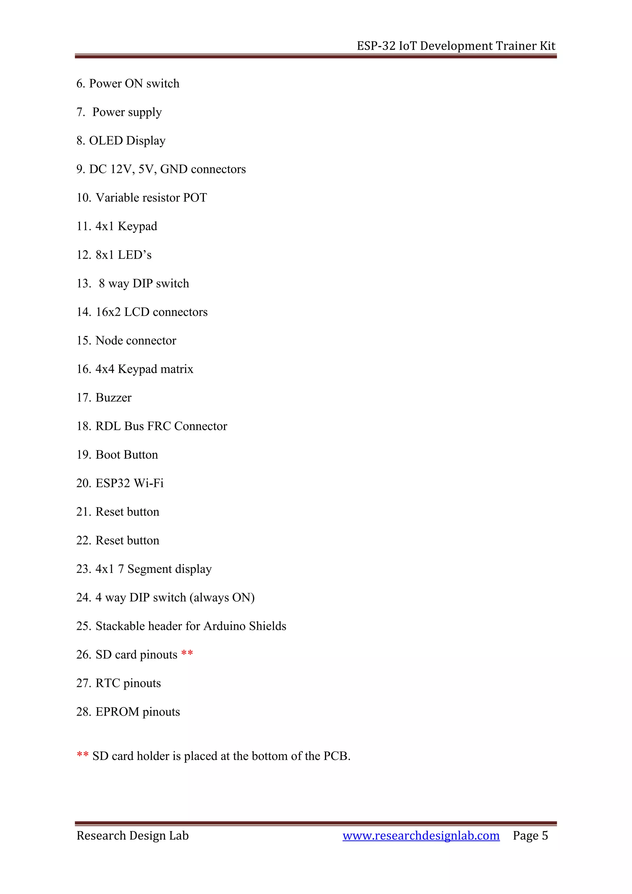
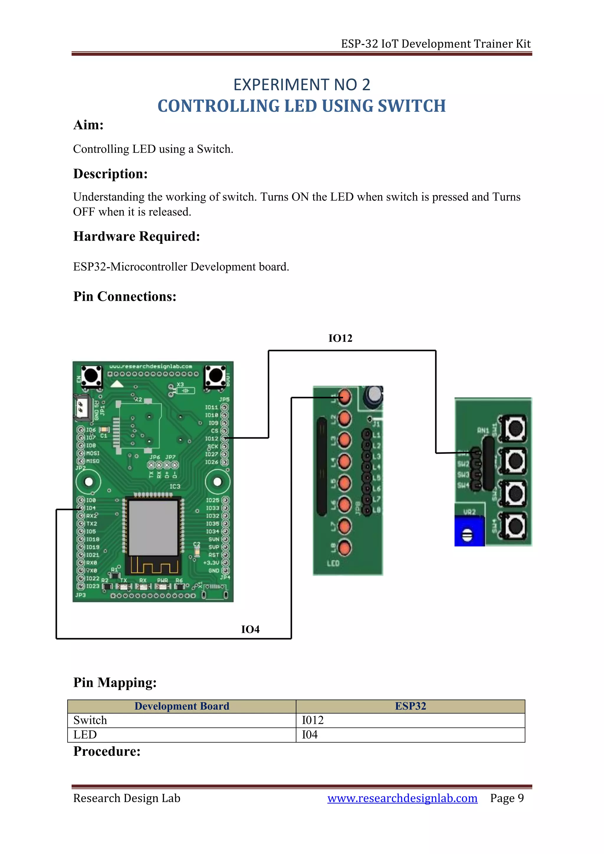
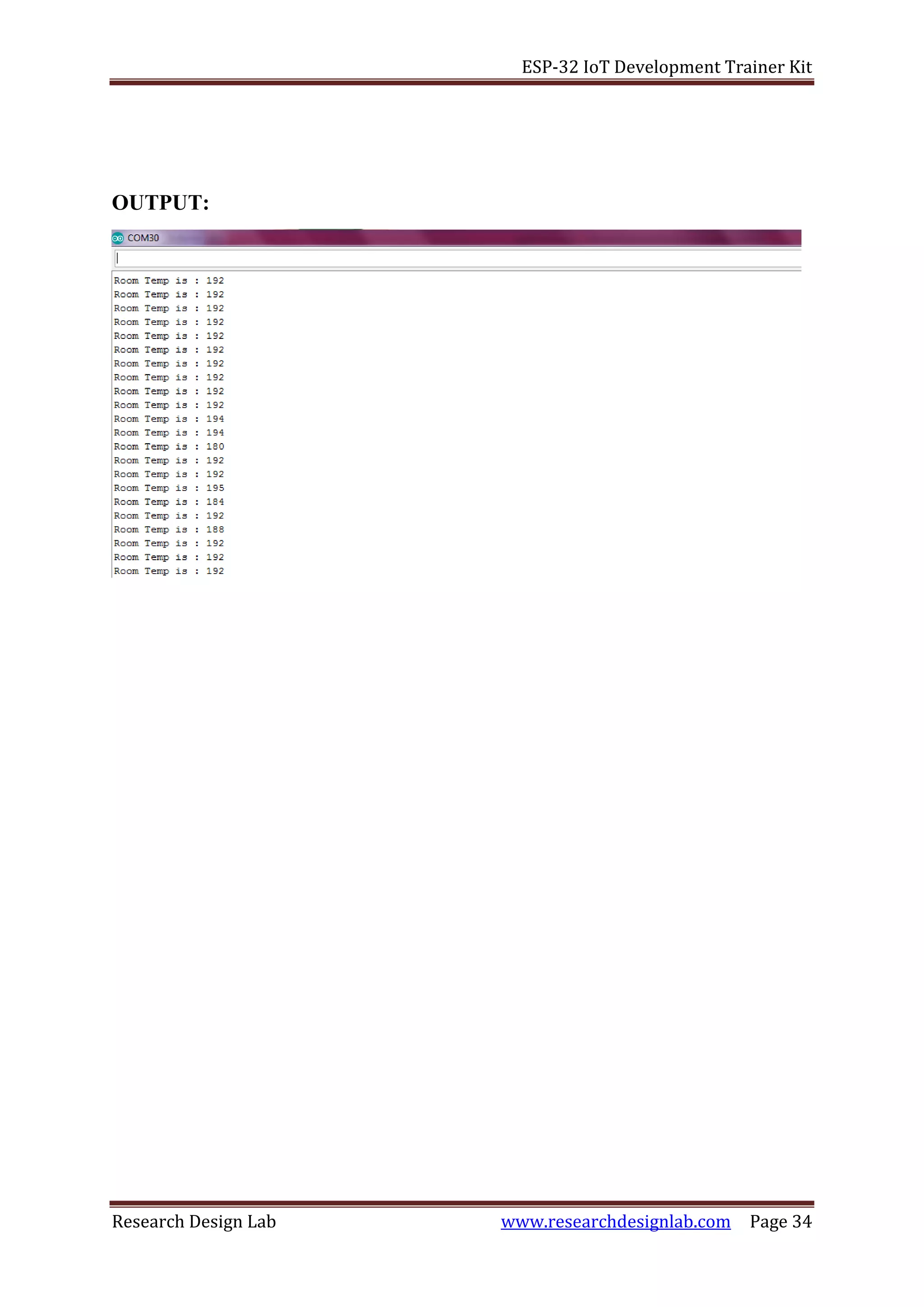
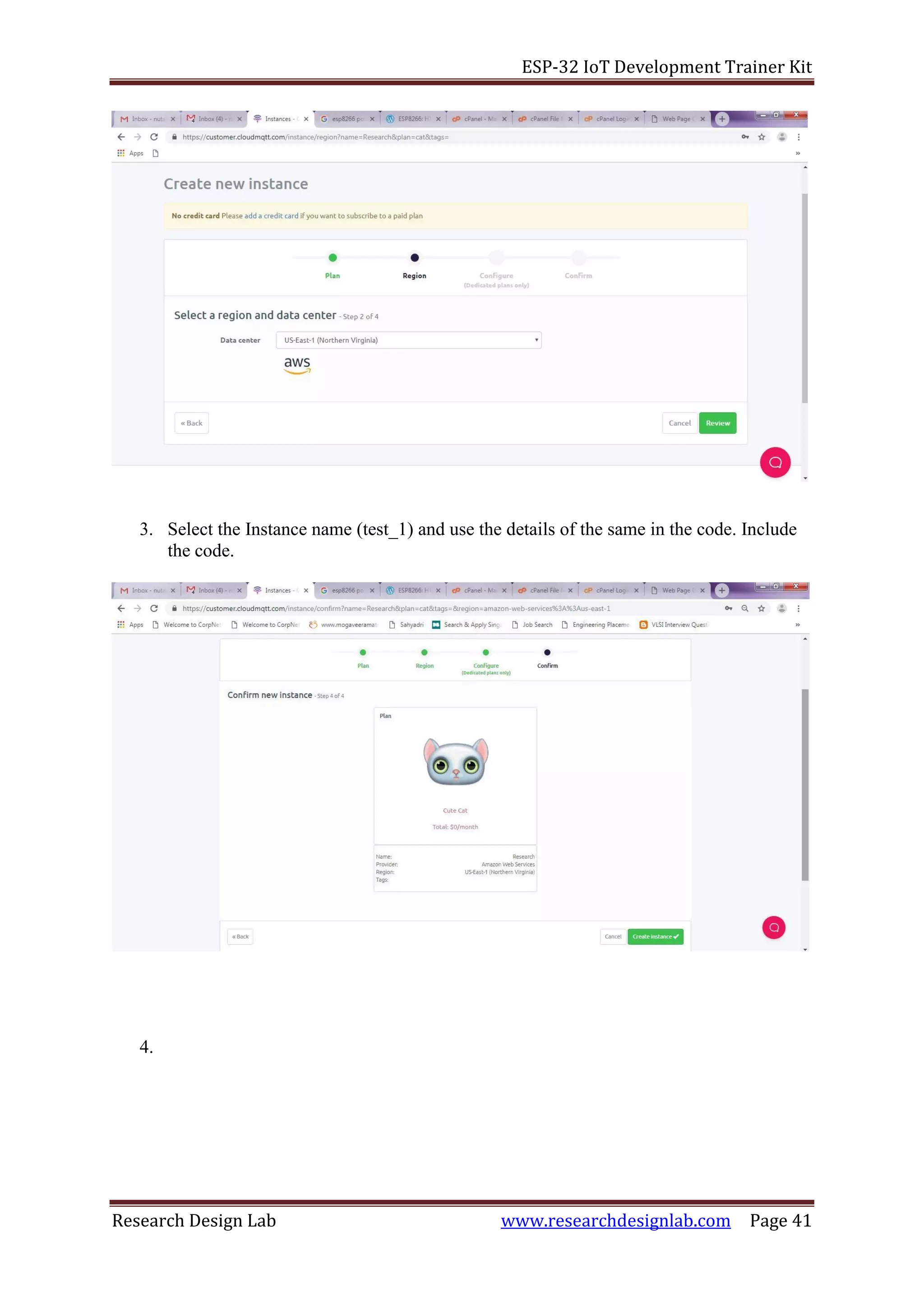
7. To send data from CloudMQTT ,include the line client.subscribe("Topic_name");
8. The following code prints the received data from the cloud in the Serial Monitor
void callback(char* topic, byte* payload, unsigned int length)
{
uint8_t s;
Serial.print("Message arrived in topic: ");
Serial.println(topic);
Serial.print("Message:");
for (int i = 0; i < length; i++)
{
s= payload[i];
Serial.write(s);
}
}](https://image.slidesharecdn.com/rdlesp32developmentboardtrainerkit-190829074544/75/Rdl-esp32-development-board-trainer-kit-43-2048.jpg)
![ESP-32 IoT Development Trainer Kit
Research Design Lab www.researchdesignlab.com Page 45
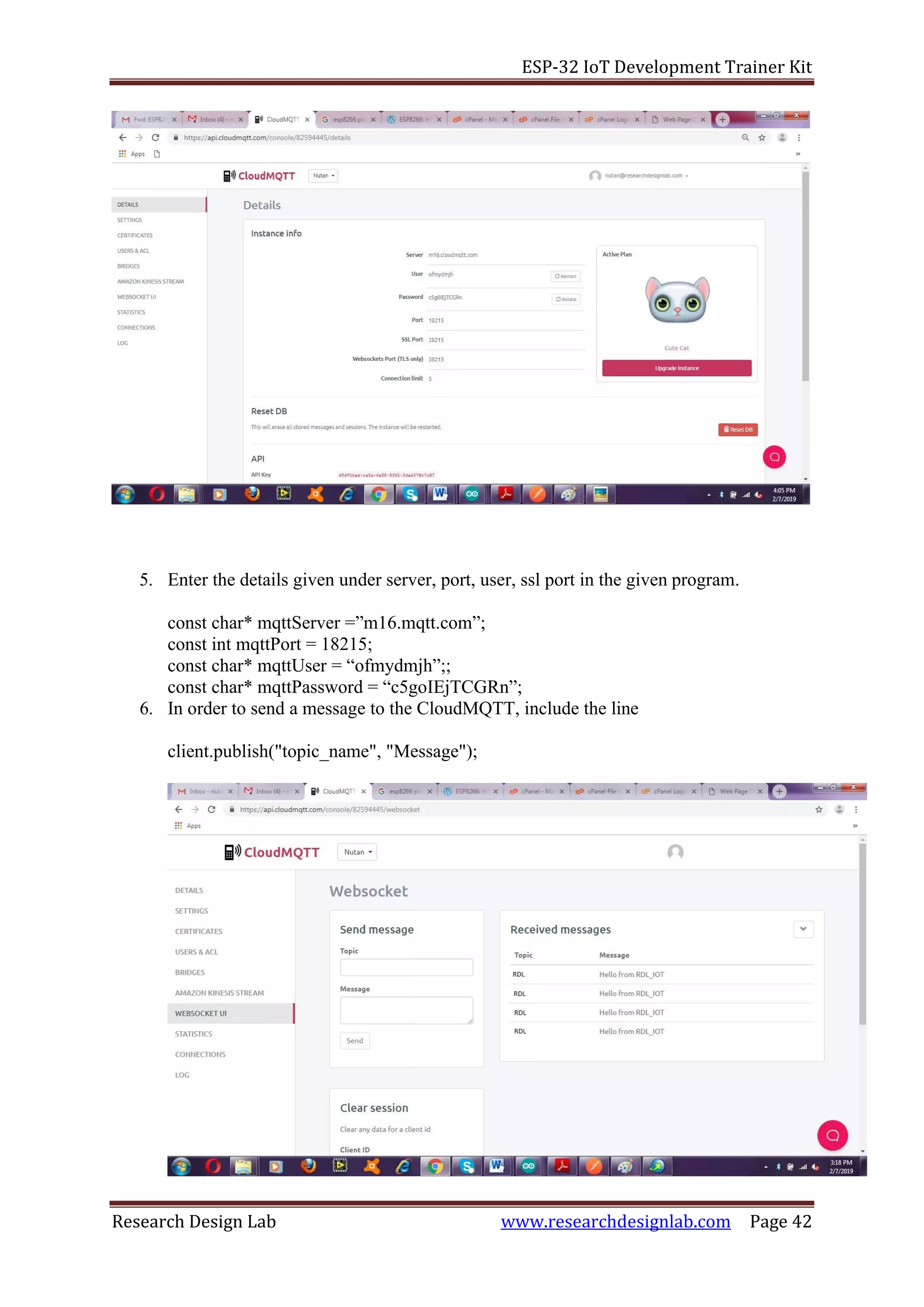
{
Serial.print("failed with state ");
Serial.print(client.state());
delay(2000);
}
}
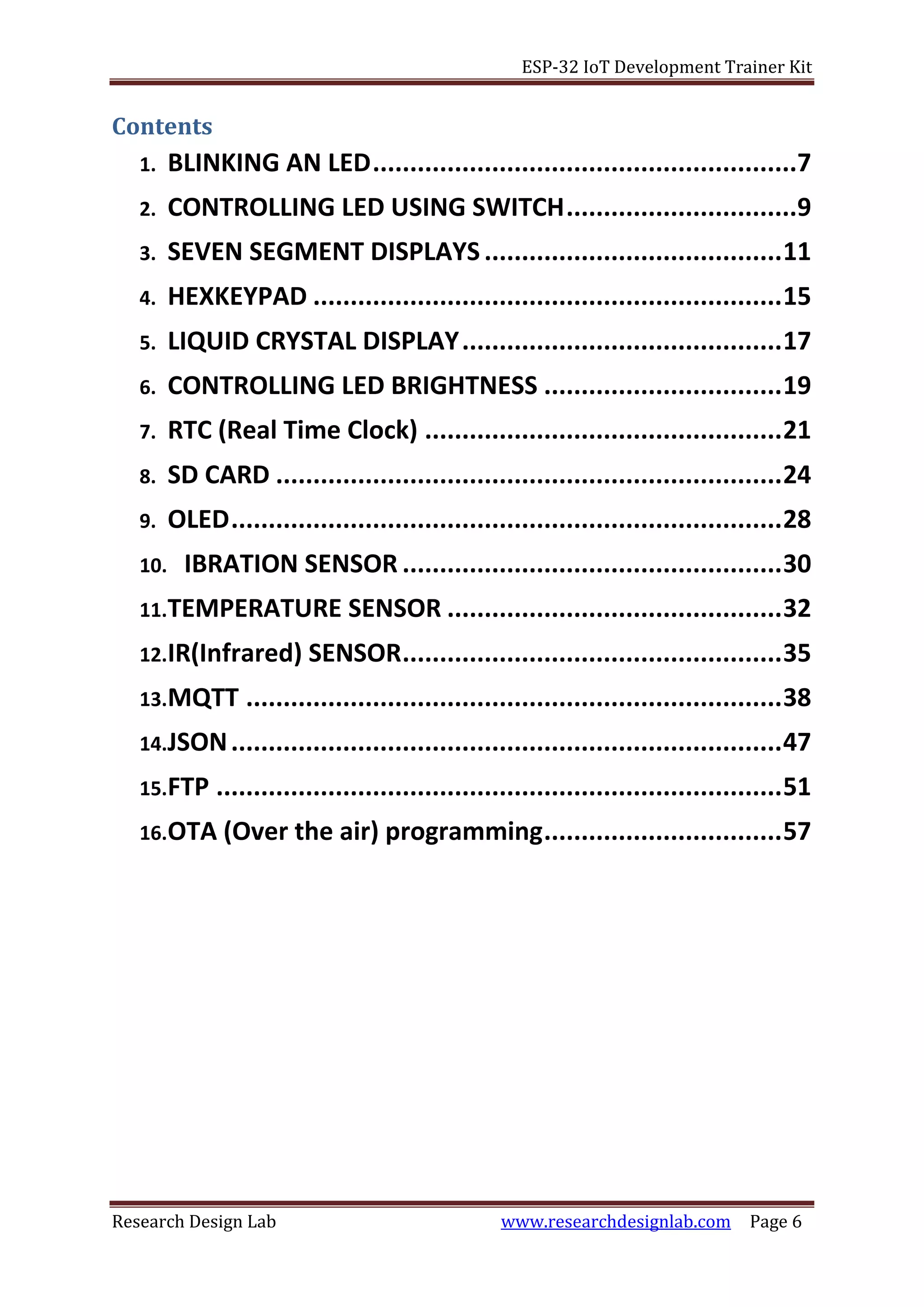
/* Sending message to Topic "test1" */
client.publish("ABC", "Hello from RDL_IOT");
client.subscribe("test"); //Receives message sent to the topic "test"
}
/* This function is used to print the incoming data sent to the topic "test" */
void callback(char* topic, byte* payload, unsigned int length)
{
uint8_t s;
Serial.print("Message arrived in topic: ");
Serial.println(topic);
Serial.print("Message:");
for (int i = 0; i < length; i++)
{
s= payload[i];
Serial.write(s);
}
}
void loop(void)
{
client.loop();
}](https://image.slidesharecdn.com/rdlesp32developmentboardtrainerkit-190829074544/75/Rdl-esp32-development-board-trainer-kit-45-2048.jpg)
![ESP-32 IoT Development Trainer Kit
Research Design Lab www.researchdesignlab.com Page 48
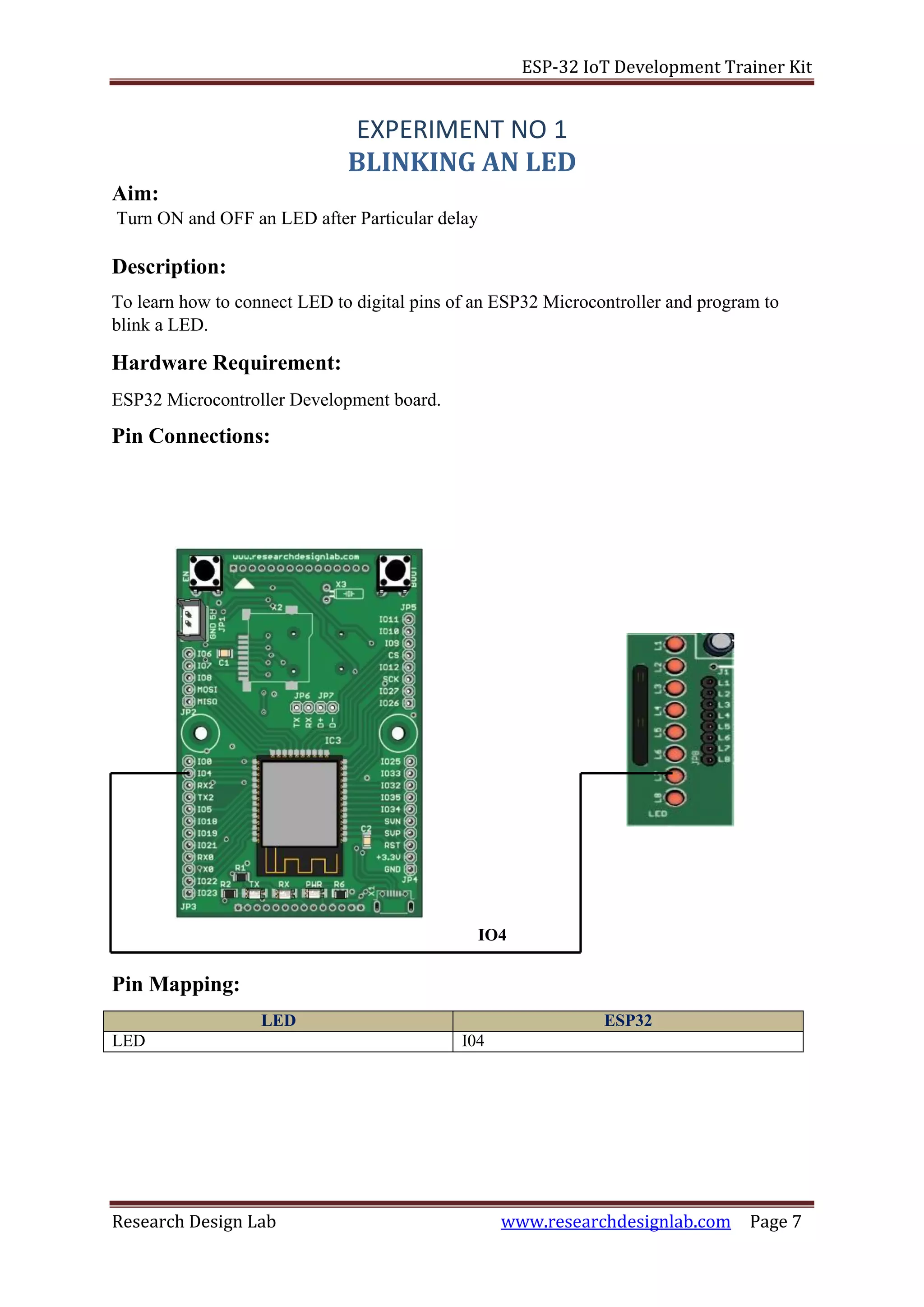
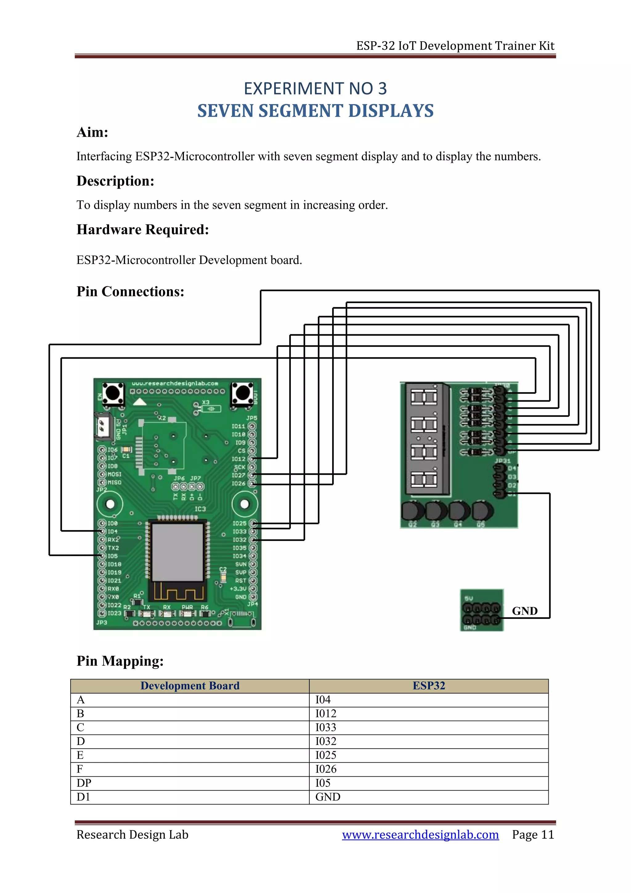
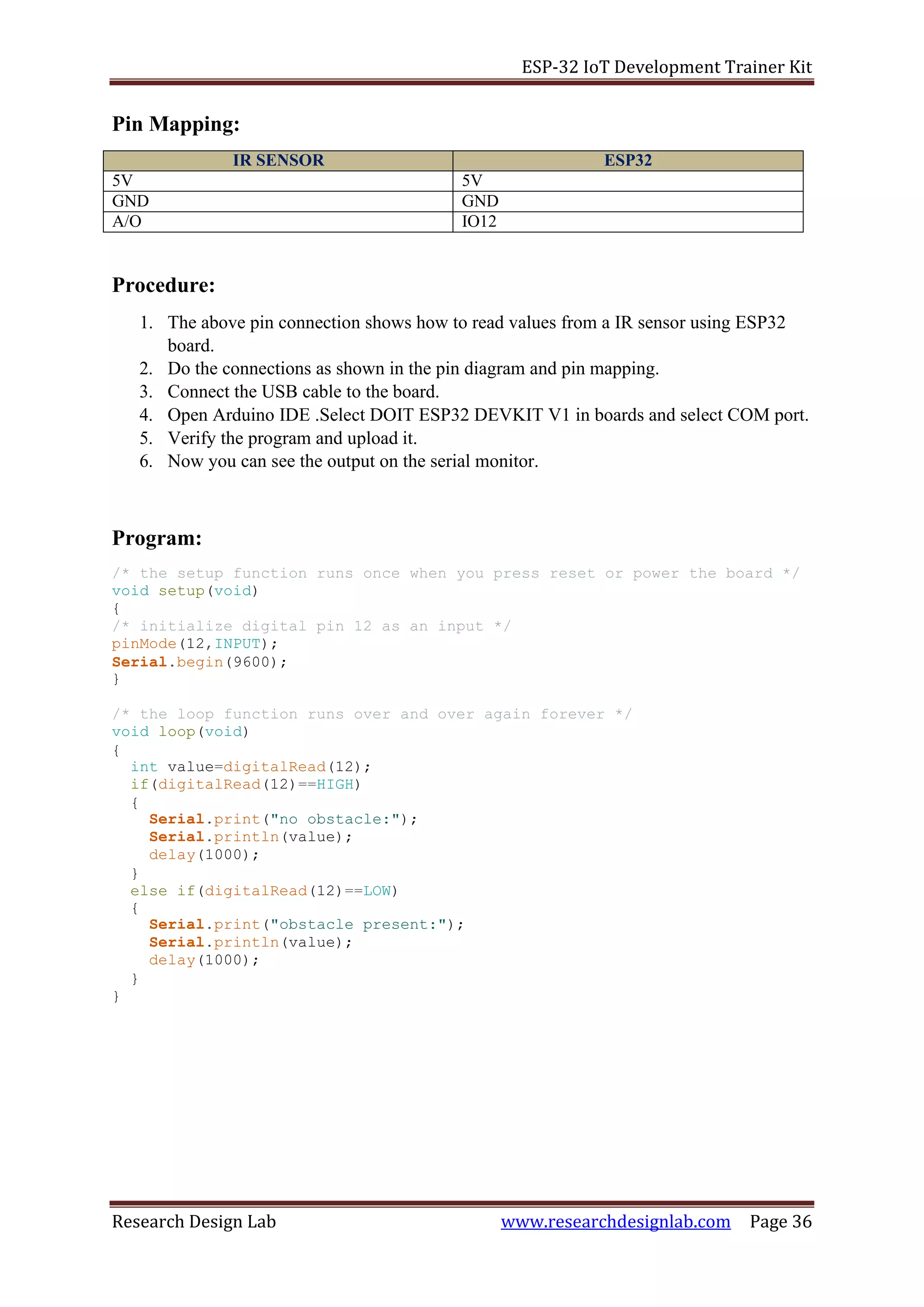
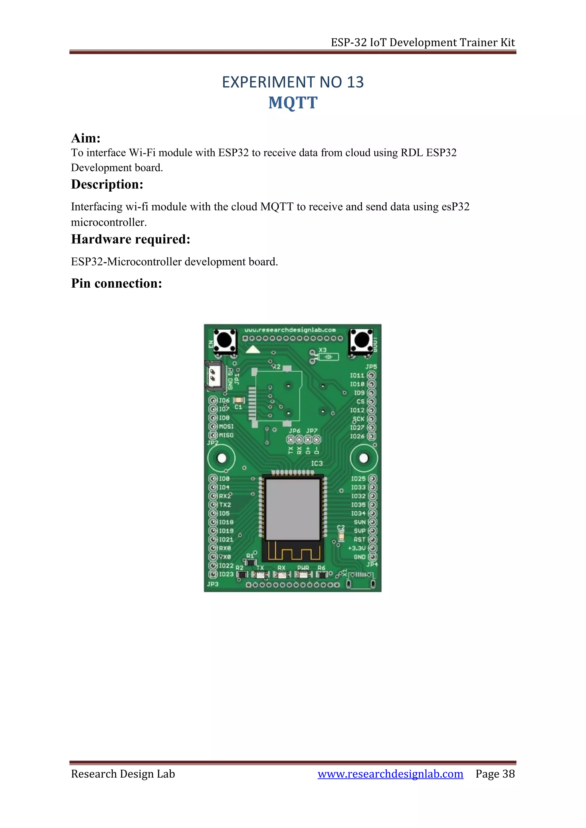
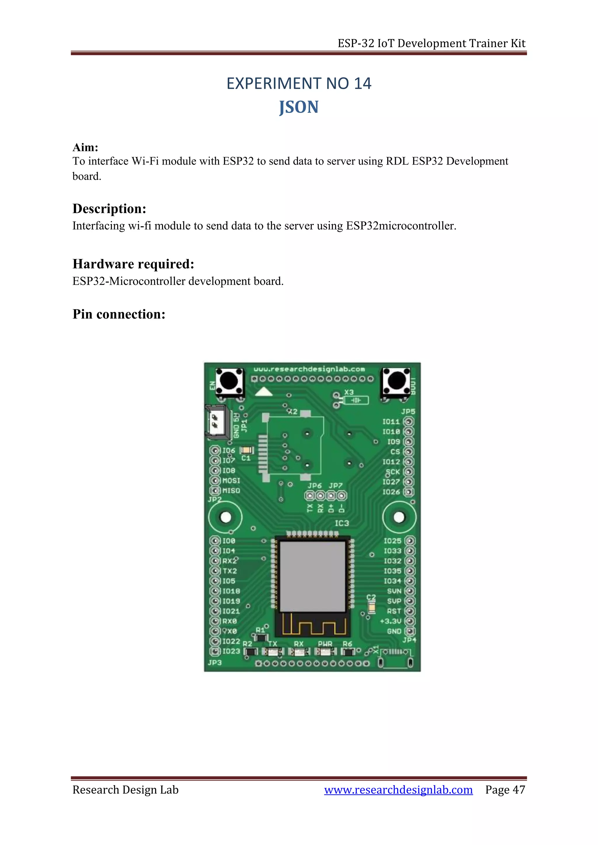
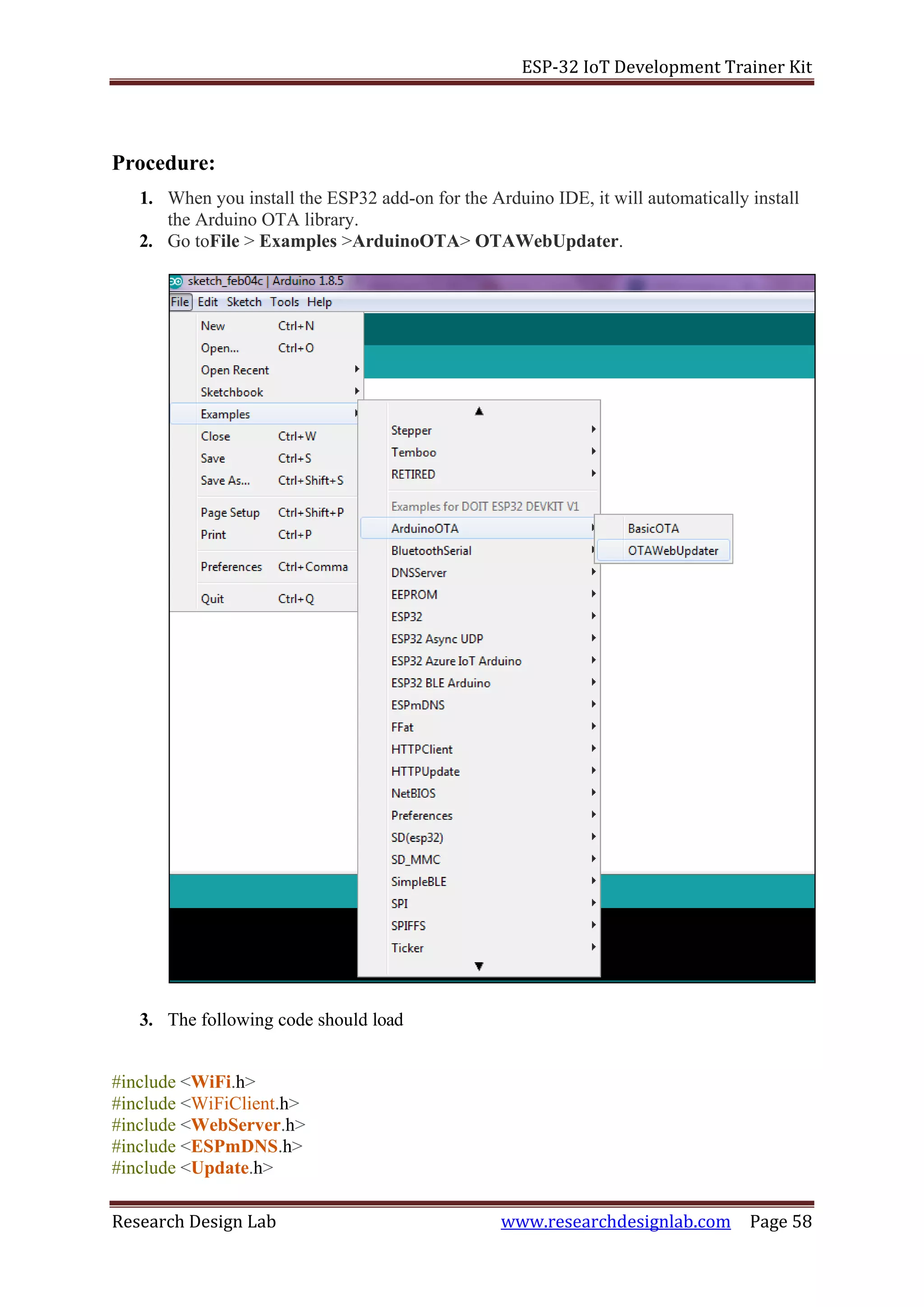
Procedure:
1. Connect the USB cable to the ESP32 development board.
2. Open Arduino IDE .Select DOIT ESP32 DEVKIT V1in boards and select COM port.
3. Verify the program and upload it.
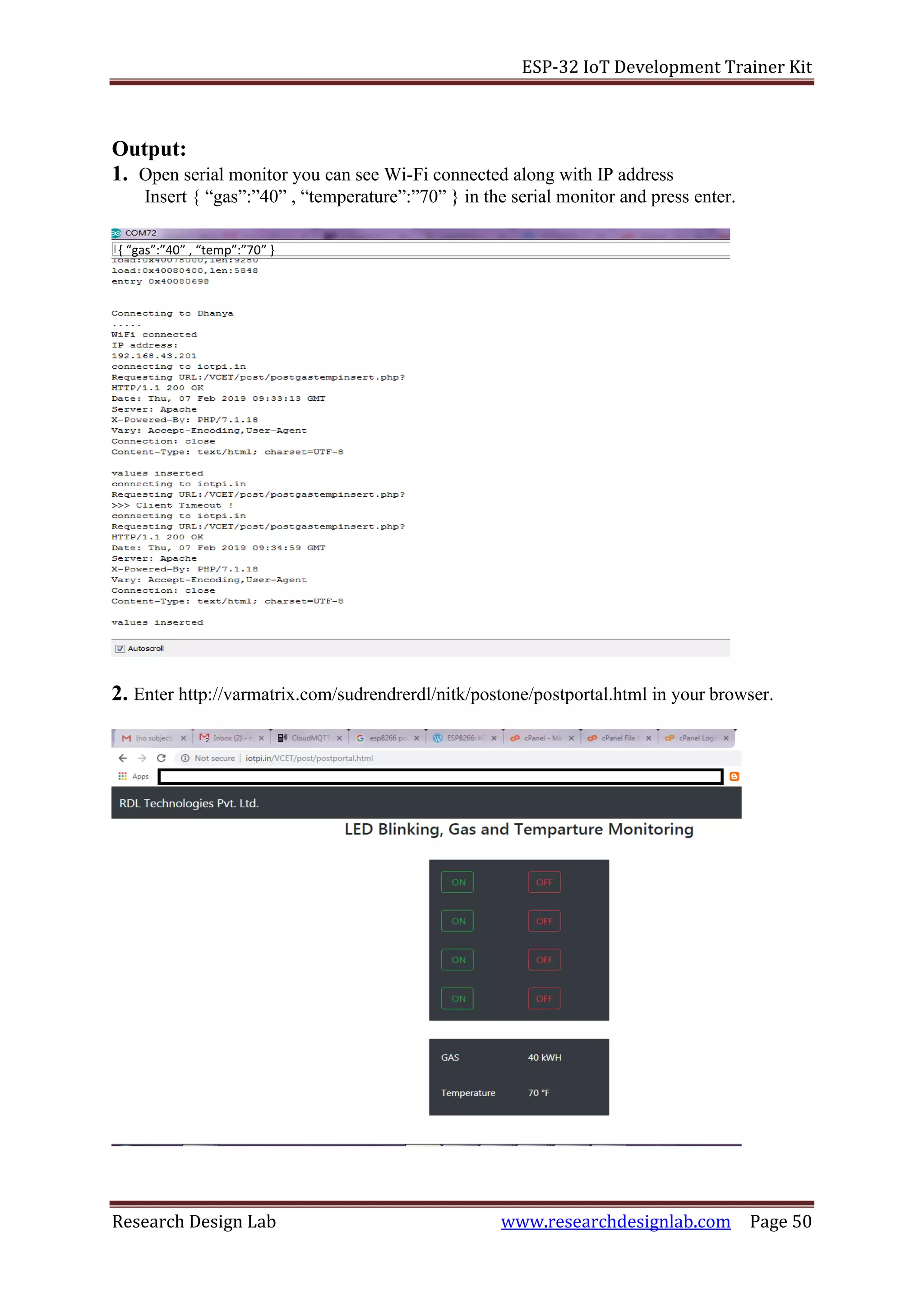
4. Now you can see wifi connected along with the IP address on the serial monitor.
5. To check the inserted values of gas and temperature use the server address and check
it on the browser.
Program:
/*
* This sketch sends data via HTTP POST requests to data.sparkfun.com
service.
*
* You need to get streamId and privateKey at data.sparkfun.com and paste
them
* below. Or just customize this script to talk to other HTTP servers.
*
*/
#include <WiFi.h>
char ssid[] = "your ssid";
char password[] = "your password";
const char* host = "varmatrix.com";
const char* streamId = "....................";
const char* privateKey = "....................";
//http://varmatrix.com/surendrardl/nitk/getone/insert.php?
WiFiClient esp32client;
void setup() {
Serial.begin(115200);
delay(10);
// We start by connecting to a WiFi network
Serial.println();
Serial.println();
Serial.print("Connecting to ");
Serial.println(ssid);
/* Explicitly set the ESP8266 to be a WiFi-client, otherwise, it by
default,
would try to act as both a client and an access-point and could cause
network-issues with your other WiFi-devices on your WiFi-network. */
//WiFi.mode(WIFI_STA);
WiFi.begin(ssid, password);
while (WiFi.status() != WL_CONNECTED) {
delay(500);
Serial.print(".");
}
Serial.println("");
Serial.println("WiFi connected");
Serial.println("IP address: ");
Serial.println(WiFi.localIP());
}
int value = 0;](https://image.slidesharecdn.com/rdlesp32developmentboardtrainerkit-190829074544/75/Rdl-esp32-development-board-trainer-kit-48-2048.jpg)
![ESP-32 IoT Development Trainer Kit
Research Design Lab www.researchdesignlab.com Page 52
Program:
#include <SD.h>
#include <SPI.h>
#include <WiFi.h>
/* comment out next line to write to SD from FTP server */
#define FTPWRITE
/* change to your network settings */
const char* ssid = "your username";
const char* password = "your password";
/* ftp server */
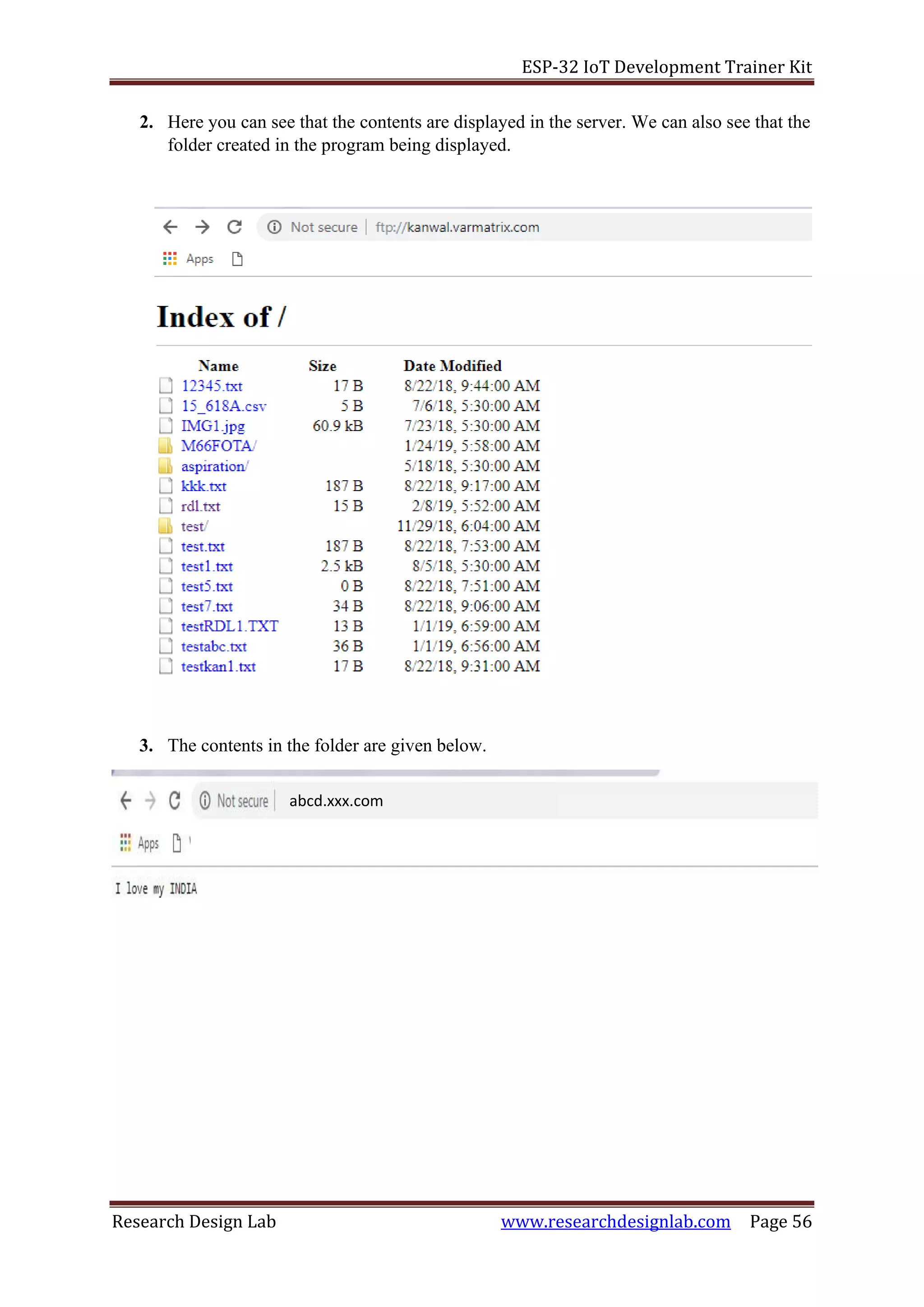
char server_link[] = "abcd.xxxxx.com";
byte clientBuf[]="i love my INDIA";
/* size of data string */
int clientCount = sizeof(clientBuf);
/* change to your server */
/* IPAddress server( 1, 2, 3, 4 ); */
WiFiClient client;
WiFiClient dclient;
char outBuf[128];
char outCount;
/* change fileName to your file (8.3 format!) */
char fileName[13] = "rdl.txt";
void setup(void)
{
Serial.begin(115200);
WiFi.mode(WIFI_STA);
WiFi.begin(ssid, password);
while (WiFi.status() != WL_CONNECTED)
{
delay(500);
Serial.print(".");
}
Serial.println("");
Serial.println("WiFi connected");
Serial.println("IP address: ");
Serial.println(WiFi.localIP());
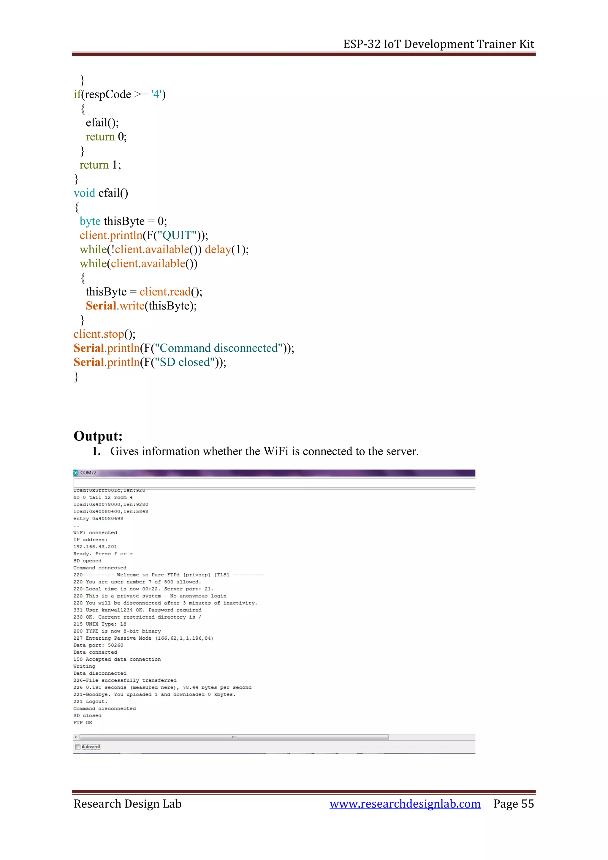
Serial.println(F("Ready. Press f or r"));
}
void loop(void)
{
byte inChar;
inChar = Serial.read();
if(inChar == 'f')
{
if(doFTP()) Serial.println(F("FTP OK"));
else Serial.println(F("FTP FAIL"));
}
}](https://image.slidesharecdn.com/rdlesp32developmentboardtrainerkit-190829074544/75/Rdl-esp32-development-board-trainer-kit-52-2048.jpg)
![ESP-32 IoT Development Trainer Kit
Research Design Lab www.researchdesignlab.com Page 53
byte doFTP()
{
Serial.println(F("SD opened"));
if (client.connect(server_link,21)) {
Serial.println(F("Command connected"));
}
else
{
Serial.println(F("Command connection failed"));
return 0;
}
if(!eRcv()) return 0;
/* ftp username */
client.println(F("USER xxxxxxx"));
if(!eRcv()) return 0;
/* ftp password */
client.println(F("PASS xxxx@13xx5"));
if(!eRcv()) return 0;
client.println(F("SYST"));
if(!eRcv()) return 0;
client.println(F("Type I"));
if(!eRcv()) return 0;
client.println(F("PASV"));
if(!eRcv()) return 0;
char *tStr = strtok(outBuf,"(,");
int array_pasv[6];
for ( int i = 0; i < 6; i++) {
tStr = strtok(NULL,"(,");
array_pasv[i] = atoi(tStr);
if(tStr == NULL)
{
Serial.println(F("Bad PASV Answer"));
}
}
unsigned int hiPort,loPort;
hiPort = array_pasv[4] << 8;
loPort = array_pasv[5] & 255;
Serial.print(F("Data port: "));
hiPort = hiPort | loPort;
Serial.println(hiPort);
if (dclient.connect(server_link,hiPort)) {
Serial.println(F("Data connected"));
}
else {
Serial.println(F("Data connection failed"));
client.stop();
return 0;
}
#ifdef FTPWRITE
client.print(F("STOR "));](https://image.slidesharecdn.com/rdlesp32developmentboardtrainerkit-190829074544/75/Rdl-esp32-development-board-trainer-kit-53-2048.jpg)
![ESP-32 IoT Development Trainer Kit
Research Design Lab www.researchdesignlab.com Page 54
client.println(fileName);
#else
client.print(F("RETR "));
client.println(fileName);
#endif
if(!eRcv())
{
dclient.stop();
return 0;
}
#ifdef FTPWRITE
Serial.println(F("Writing"));
if(clientCount > 0) dclient.write(clientBuf,clientCount);
#else
while(dclient.connected())
{
while(dclient.available())
{
char c = dclient.read();
Serial.write(c);
}
}
#endif
dclient.stop();
Serial.println(F("Data disconnected"));
if(!eRcv()) return 0;
client.println(F("QUIT"));
if(!eRcv()) return 0;
client.stop();
Serial.println(F("Command disconnected"));
Serial.println(F("SD closed"));
return 1;
}
byte eRcv()
{
byte respCode;
byte thisByte;
while(!client.available()) delay(1);
respCode = client.peek();
outCount = 0;
while(client.available())
{
thisByte = client.read();
Serial.write(thisByte);
if(outCount < 127)
{
outBuf[outCount] = thisByte;
outCount++;
outBuf[outCount] = 0;
}](https://image.slidesharecdn.com/rdlesp32developmentboardtrainerkit-190829074544/75/Rdl-esp32-development-board-trainer-kit-54-2048.jpg)
![ESP-32 IoT Development Trainer Kit
Research Design Lab www.researchdesignlab.com Page 60
"</script>";
/*
* Server Index Page
*/
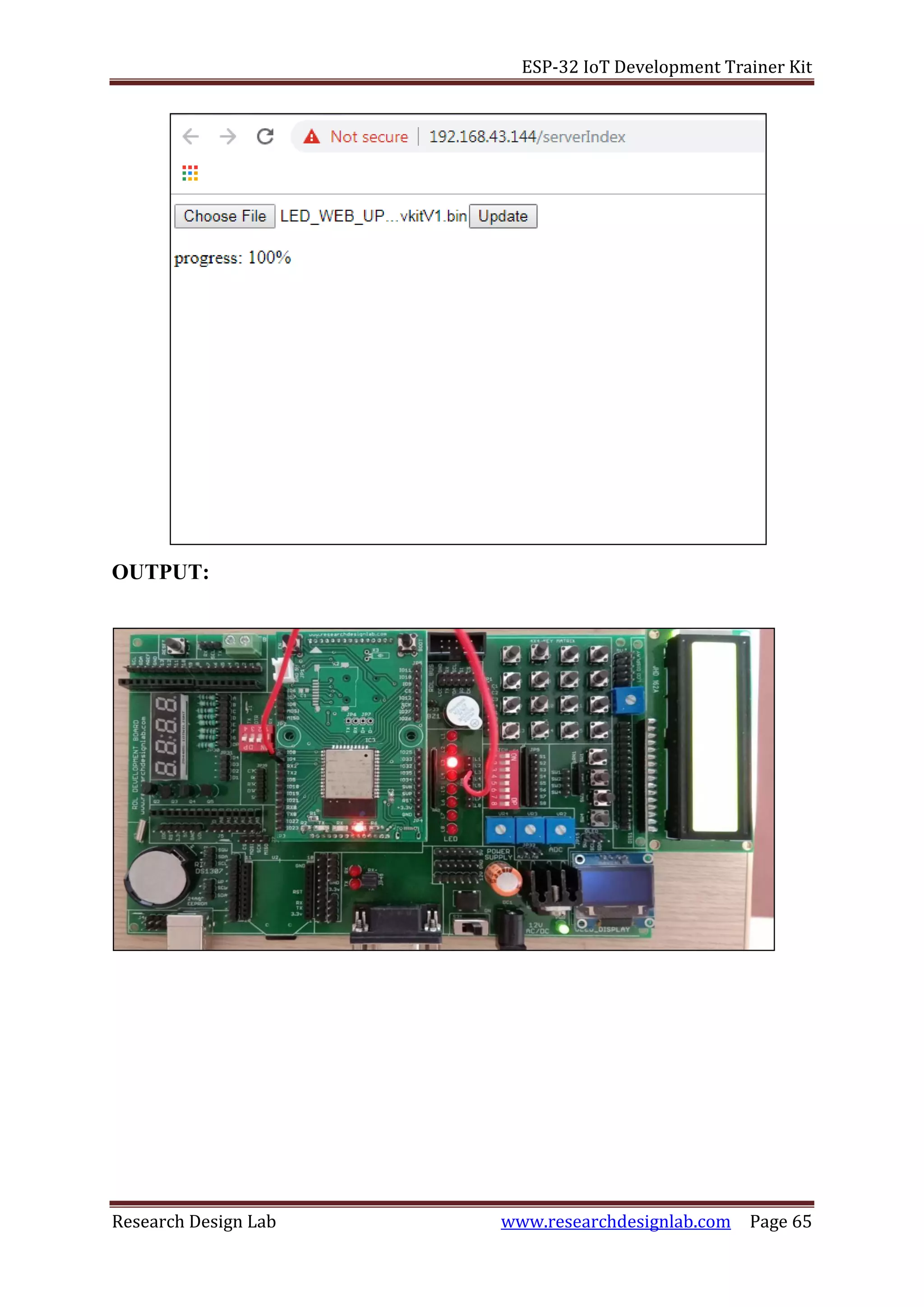
const char* serverIndex =
"<script src='https://ajax.googleapis.com/ajax/libs/jquery/3.2.1/jquery.min.js'></script>"
"<form method='POST' action='#' enctype='multipart/form-data' id='upload_form'>"
"<input type='file' name='update'>"
"<input type='submit' value='Update'>"
"</form>"
"<div id='prg'>progress: 0%</div>"
"<script>"
"$('form').submit(function(e){"
"e.preventDefault();"
"var form = $('#upload_form')[0];"
"var data = new FormData(form);"
" $.ajax({"
"url: '/update',"
"type: 'POST',"
"data: data,"
"contentType: false,"
"processData:false,"
"xhr: function() {"
"var xhr = new window.XMLHttpRequest();"
"xhr.upload.addEventListener('progress', function(evt) {"
"if (evt.lengthComputable) {"
"var per = evt.loaded / evt.total;"
"$('#prg').html('progress: ' + Math.round(per*100) + '%');"
"}"
"}, false);"
"return xhr;"
"},"
"success:function(d, s) {"
"console.log('success!')"
"},"
"error: function (a, b, c) {"
"}"
"});"
"});"
"</script>";
/*
* setup function
*/
void setup(void) {
Serial.begin(115200);
// Connect to WiFi network](https://image.slidesharecdn.com/rdlesp32developmentboardtrainerkit-190829074544/75/Rdl-esp32-development-board-trainer-kit-60-2048.jpg)
![ESP-32 IoT Development Trainer Kit
Research Design Lab www.researchdesignlab.com Page 61
WiFi.begin(ssid, password);
Serial.println("");
// Wait for connection
while (WiFi.status() != WL_CONNECTED) {
delay(500);
Serial.print(".");
}
Serial.println("");
Serial.print("Connected to ");
Serial.println(ssid);
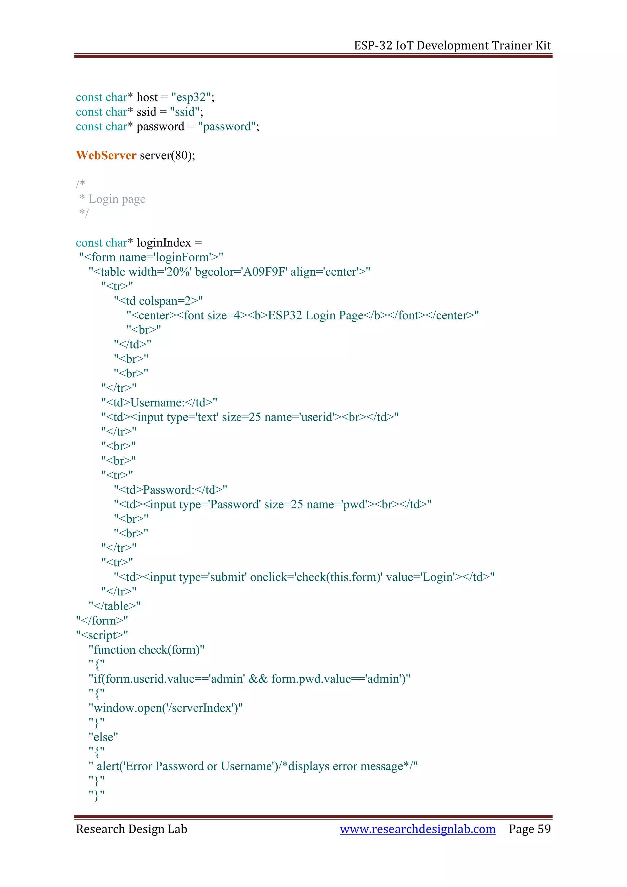
Serial.print("IP address: ");
Serial.println(WiFi.localIP());
/*use mdns for host name resolution*/
if (!MDNS.begin(host)) { //http://esp32.local
Serial.println("Error setting up MDNS responder!");
while (1) {
delay(1000);
}
}
Serial.println("mDNS responder started");
/*return index page which is stored in serverIndex */
server.on("/", HTTP_GET, []() {
server.sendHeader("Connection", "close");
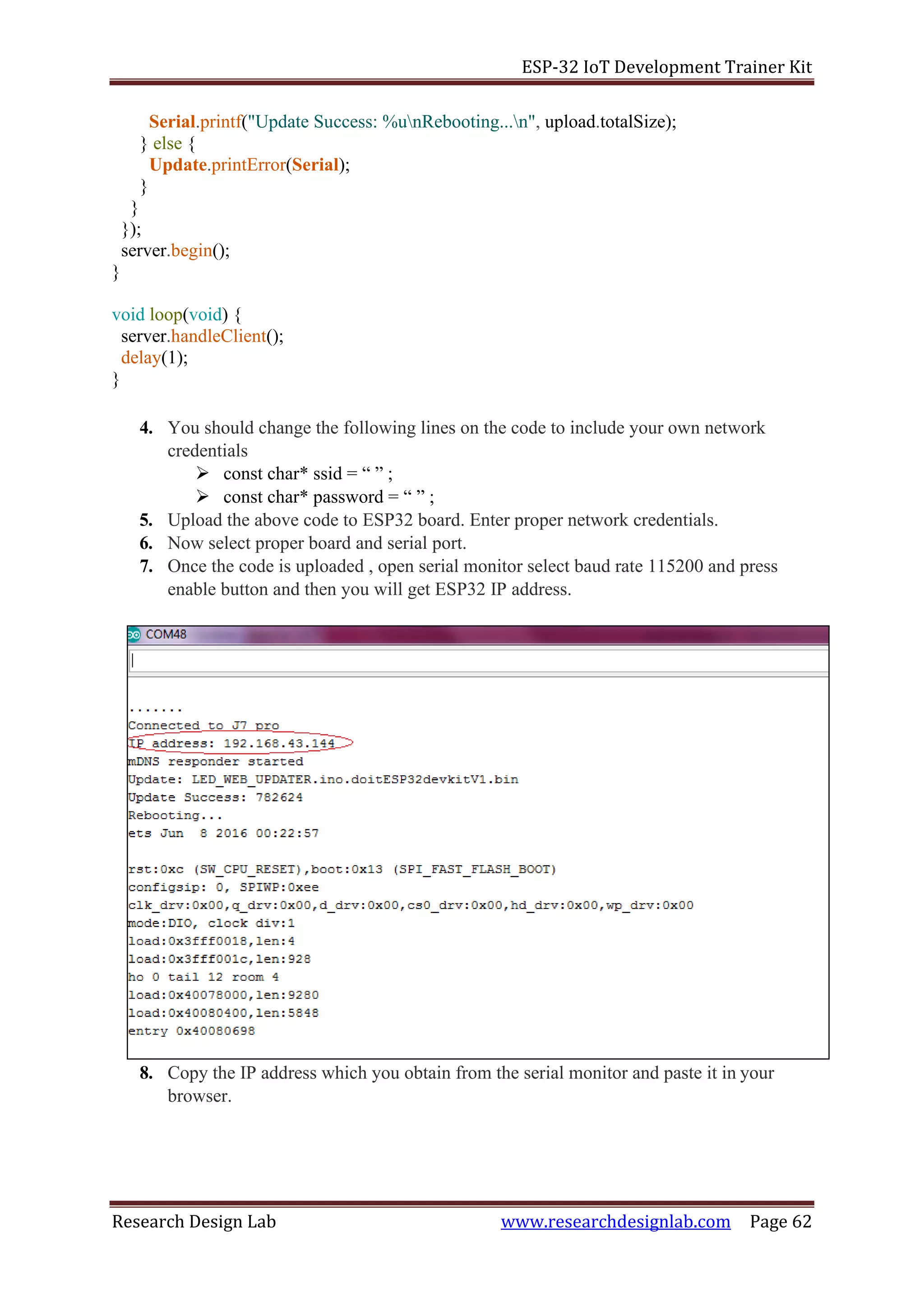
server.send(200, "text/html", loginIndex);
});
server.on("/serverIndex", HTTP_GET, []() {
server.sendHeader("Connection", "close");
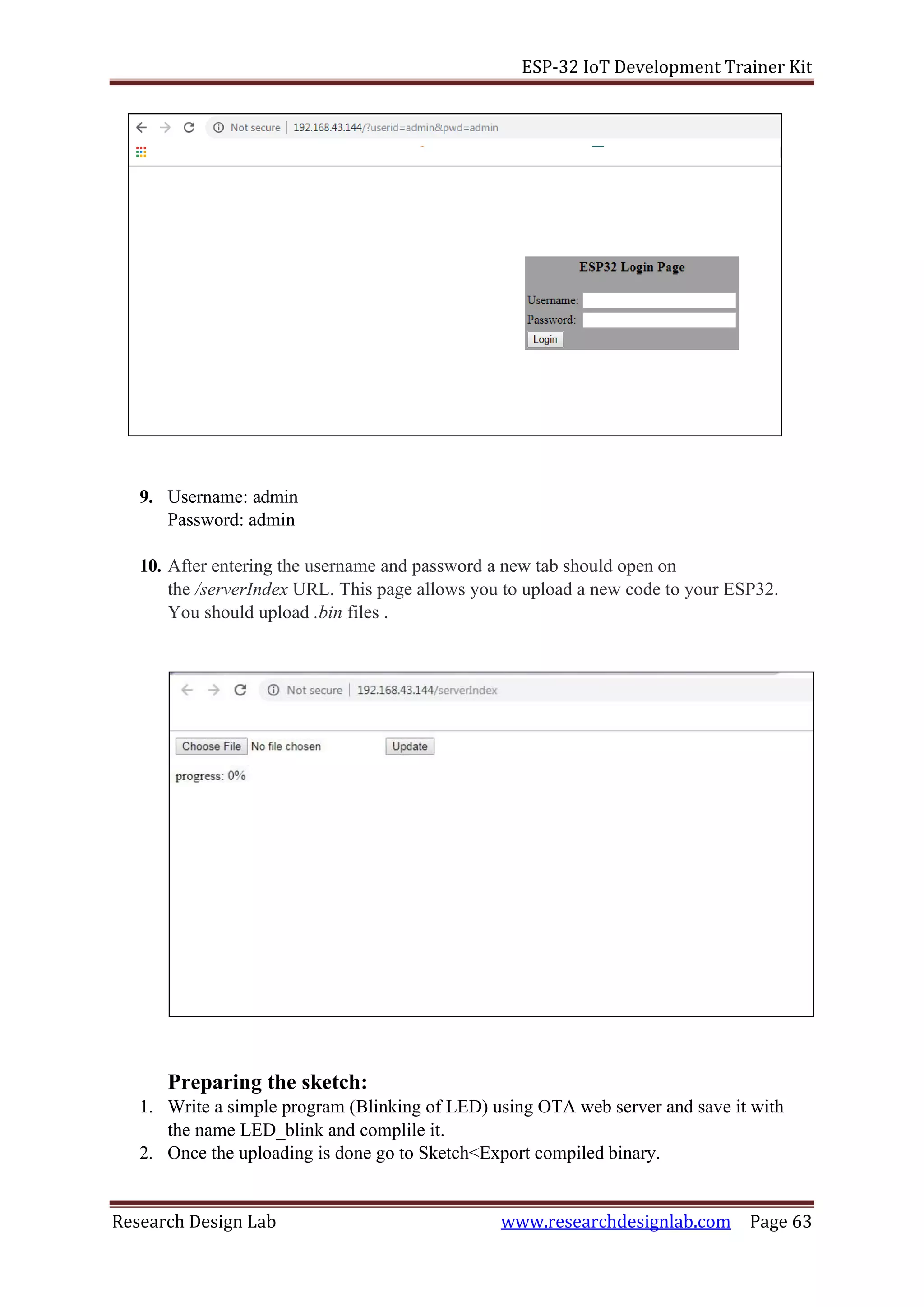
server.send(200, "text/html", serverIndex);
});
/*handling uploading firmware file */
server.on("/update", HTTP_POST, []() {
server.sendHeader("Connection", "close");
server.send(200, "text/plain", (Update.hasError()) ? "FAIL" : "OK");
ESP.restart();
}, []() {
HTTPUpload& upload = server.upload();
if (upload.status == UPLOAD_FILE_START) {
Serial.printf("Update: %sn", upload.filename.c_str());
if (!Update.begin(UPDATE_SIZE_UNKNOWN)) { //start with max available size
Update.printError(Serial);
}
} else if (upload.status == UPLOAD_FILE_WRITE) {
/* flashing firmware to ESP*/
if (Update.write(upload.buf, upload.currentSize) != upload.currentSize) {
Update.printError(Serial);
}
} else if (upload.status == UPLOAD_FILE_END) {
if (Update.end(true)) { //true to set the size to the current progress](https://image.slidesharecdn.com/rdlesp32developmentboardtrainerkit-190829074544/75/Rdl-esp32-development-board-trainer-kit-61-2048.jpg)

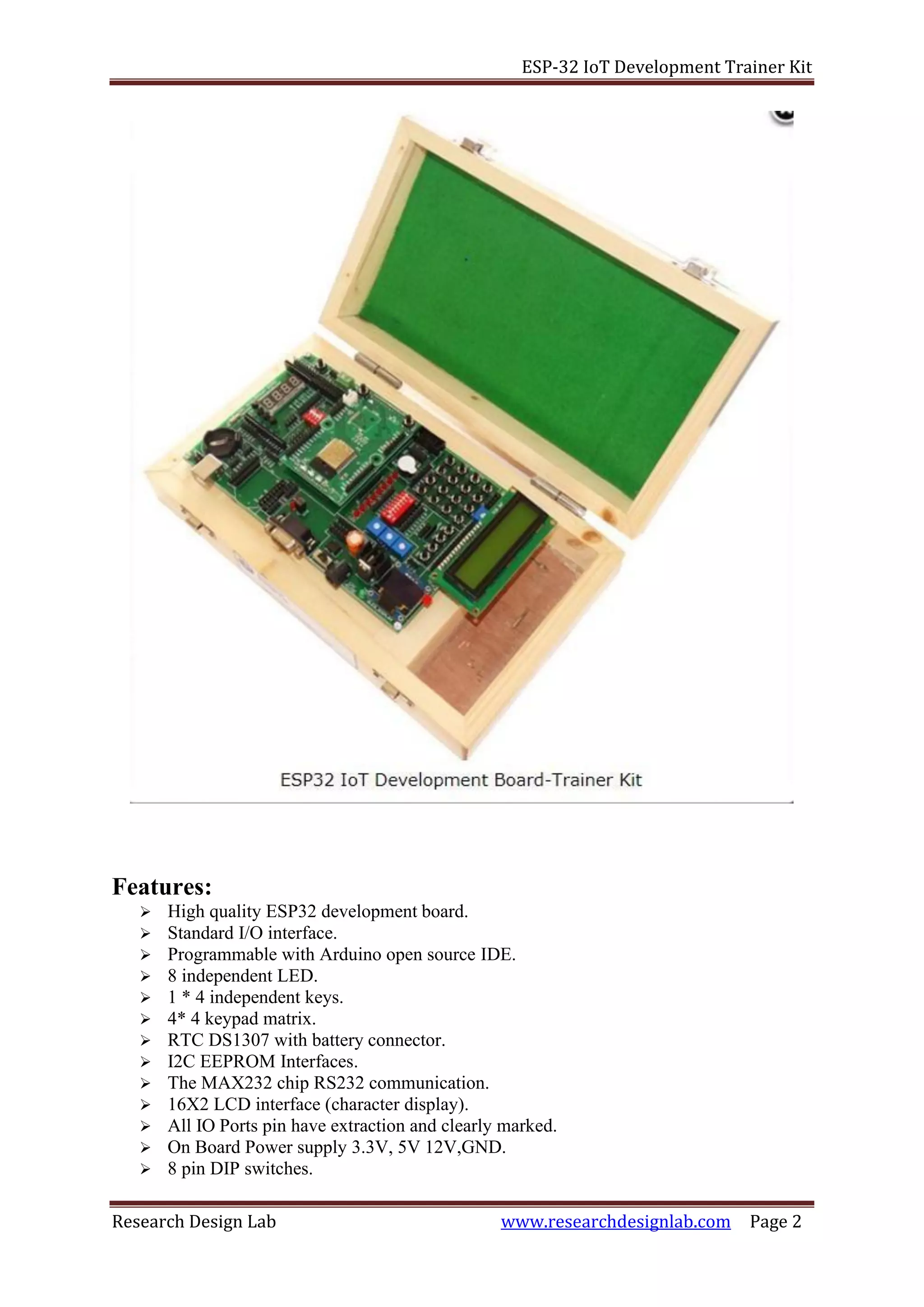
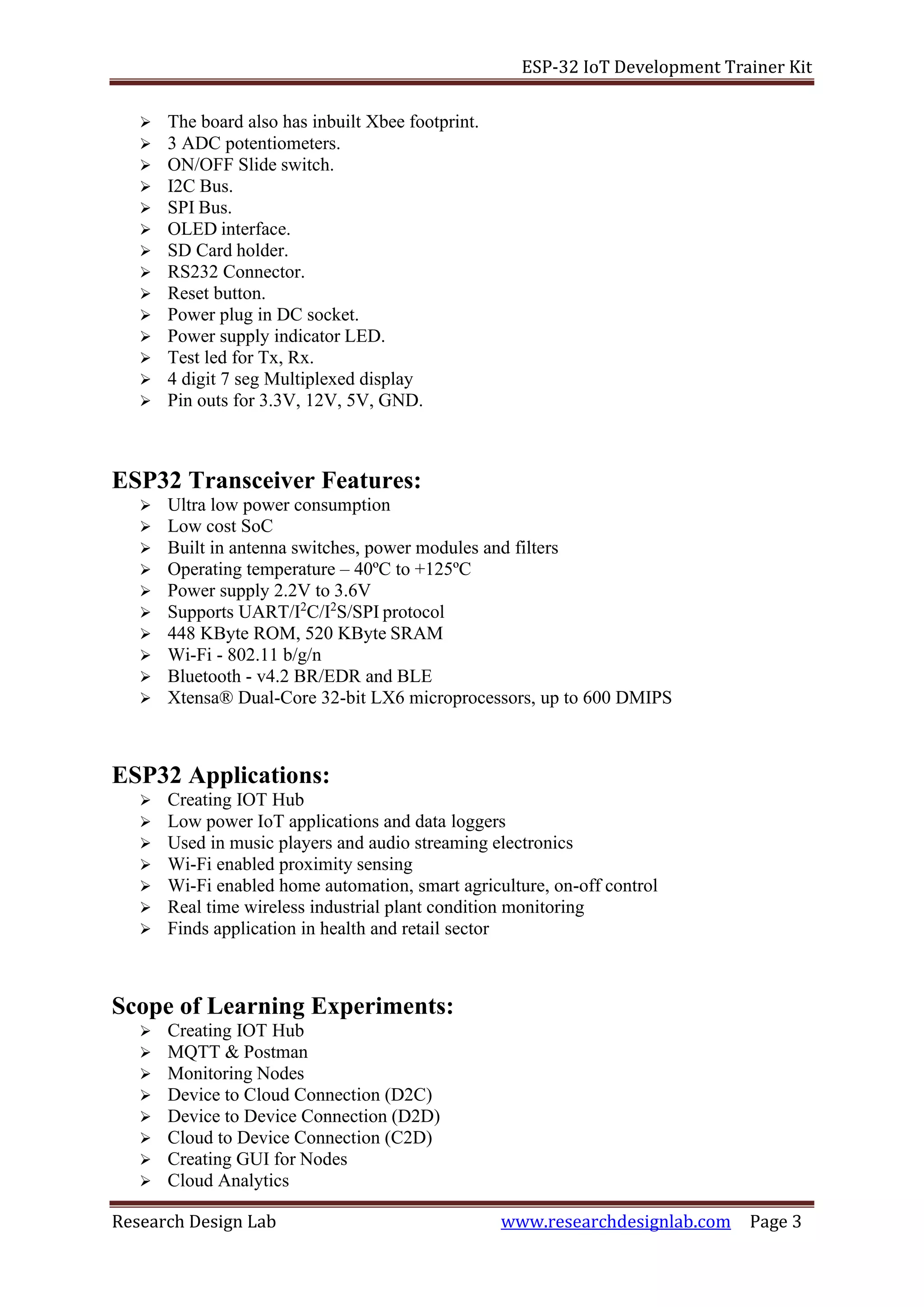
The document describes the ESP-32 IoT Development Trainer Kit featuring various hardware components and functionalities suitable for IoT applications, including Wi-Fi and Bluetooth capabilities. It outlines various experiments that can be conducted using the kit, focusing on interfacing with LEDs, LCDs, keypads, sensors, and more, providing hands-on learning about IoT concepts. The document includes details on the device's technical specifications, pin mappings, and programming examples for Arduino IDE.


![Introduction to ESP32 Programming [Road to RIoT 2017]](https://cdn.slidesharecdn.com/ss_thumbnails/roadtoriotsurabayagettingstartedesp32-170726155154-thumbnail.jpg?width=640&height=640&fit=bounds)