RAIN WATER HARVESTING
DR.ESTHER SHOBA R
ASSOCIATE PROFESSOR
DEPARTMENT OF LIFE SCIENCES
KRISTU JAYANTI COLLEGE
2.
INTRODUCTION
• Water iswhy life exists on planet Earth; without it, life is unimaginable.
• How will you plan your survival if one day there is no water on earth?
• Freshwater sources are becoming scarce over time.
• Unless the current water situation changes and preventive measures are
taken, the world will run out of freshwater by 2050.
• Here comes Rainwater Harvesting, a sustainable process that helps conserve
rainwater for different purposes.
• Rainwater Harvesting is best defined as the technique by which rainwater is
accumulated and stored for later use when there is a scarcity or a drought.
3.
DEFINITION
• Rainwater harvestingmay be defined as the simple technique of collection
and storage of rainwater at the surface or in the subsurface aquifer before it is
lost as surface runoff from rooftops, parks, roads, open grounds, etc., for later
use.
• Potable water is becoming scarce in many countries due to rapid climatic
changes, global warming, and population growth.
• Water levels gradually falling is a cause of serious concern because it results in
a shortage of usable water and an imbalance in salinity in coastal areas.
• Rainwater harvesting is gaining popularity as a source of eco-conservation and
constructive use of natural resources since there is no alternative to
increasing freshwater supplies.
• Rainwater harvesting is an easy and economical way to deal with this crisis.
4.
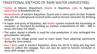
TRADITIONAL METHOD OFRAIN WATER HARVESTING
• Tankas in Bikaner (Rajasthan), khadin in Rajasthan, zabo in Nagaland,
pokhariyan in Bundelkhand etc.
• Kundis/Kunds of western Rajasthan, Gujrat and in some parts of Uttar Pradesh
also, are the underground covered tanks used to harvest rainwater for drinking
purpose.
• In hyper arid parts of Rajasthan, the khadin system involved the harvesting of
rainwater on farmland by building an earthen embankment of 100 – 300 m
across the lower hill slopes.
• The water stored in khadin is used for crop production. It also recharged the
groundwater naturally.
• Nadis are the village ponds used to store water from adjoining catchments
during the rainy season.
• Kuis / Beris used in western Rajasthan, these are 10-12 m deep pits dug near
tanks to collect the seepage. Kuis can also be used to harvest rainwater in
areas with meager rainfall.
5.
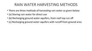
RAIN WATER HARVESTINGMETHODS
• There are three methods of harvesting rain water as given below:
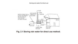
• (a) Storing rain water for direct use
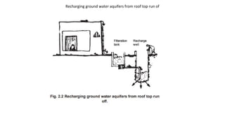
• (b) Recharging ground water aquifers, from roof top run off
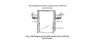
• (c) Recharging ground water aquifers with runoff from ground area
Types of RainwaterHarvesting
• There are two ways of Rainwater harvesting:
1. Rooftop Rainwater Harvesting
2. Surface Runoff Rainwater Harvesting
11.
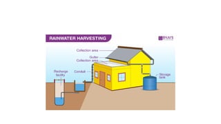
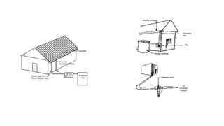
Rooftop Rainwater Harvesting
•a. Rooftop rainwater harvesting or domestic rainwater harvesting is the
technique through which rainwater is captured from roof components and
stored in tanks/reservoirs/groundwater aquifers.
• b. It consists of the conservation of rooftop rainwater in urban areas and
utilizing it to augment groundwater storage by artificial recharge.
• c. This technique is particularly useful in dryland, hilly, urban and coastal
areas.
• If the system is properly installed and maintained, clean water fit for drinking
can be collected and stored.
12.
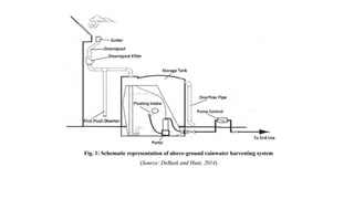
Components of RooftopRainwater Harvesting System
• The various components of rooftop rainwater harvesting system are:
• 1. Roof/catchment area
• 2. Gutters and downpipes
• 3. Filter unit or leaf screen
• 4. Storage tank
• 5. Delivery system
• 6. Water treatment unit
Catchment and CoarseMesh
• Catchment: The catchment or collection area is an area which directly
receives the rainfall and provides water to the system.
• The roof of a house or a building can be used to collect the water as these
areas are generally safe and cleaner compared the paved ground surfaces.
• The effective roof area and the material used in constructing the roof
influence the efficiency of collection and the water quality.
• Coarse Mesh: Provide at the roof to prevent entry of any debris
16.
GUTTERS AND CONDUITS
Gutters:These are the channels installed all around the edges of the sloped
roof to collect the water and deliver to the storing system via conduits.
These are semi-circular or rectangular shaped drains can be made by folding
galvanized iron (GI) sheets or by cutting Poly Vinyl Chloride (PVC) pipes and
bamboo or betel trunk vertically into the half.
Conduits: Conduits usually consists of pipes that deliver rainwater falling on the
rooftop to cisterns or other storage vessels.
To avoid adverse effects on water quality, the chemically inert materials such as
wood, plastic, aluminum, or fiberglass should be used in construction of
drainpipes and roof surfaces
17.
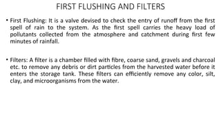
FIRST FLUSHING ANDFILTERS
• First Flushing: It is a valve devised to check the entry of runoff from the first
spell of rain to the system. As the first spell carries the heavy load of
pollutants collected from the atmosphere and catchment during first few
minutes of rainfall.
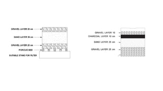
• Filters: A filter is a chamber filled with fibre, coarse sand, gravels and charcoal
etc. to remove any debris or dirt particles from the harvested water before it
enters the storage tank. These filters can efficiently remove any color, silt,
clay, and microorganisms from the water.
21.
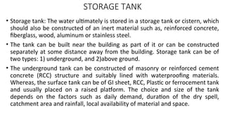
STORAGE TANK
• Storagetank: The water ultimately is stored in a storage tank or cistern, which
should also be constructed of an inert material such as, reinforced concrete,
fiberglass, wood, aluminum or stainless steel.
• The tank can be built near the building as part of it or can be constructed
separately at some distance away from the building. Storage tank can be of
two types: 1) underground, and 2)above ground.
• The underground tank can be constructed of masonry or reinforced cement
concrete (RCC) structure and suitably lined with waterproofing materials.
Whereas, the surface tank can be of GI sheet, RCC, Plastic or ferrocement tank
and usually placed on a raised platform. The choice and size of the tank
depends on the factors such as daily demand, duration of the dry spell,
catchment area and rainfall, local availability of material and space.
22.
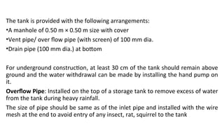
The tank isprovided with the following arrangements:
•A manhole of 0.50 m × 0.50 m size with cover
•Vent pipe/ over flow pipe (with screen) of 100 mm dia.
•Drain pipe (100 mm dia.) at bottom
For underground construction, at least 30 cm of the tank should remain above
ground and the water withdrawal can be made by installing the hand pump on
it.
Overflow Pipe: Installed on the top of a storage tank to remove excess of water
from the tank during heavy rainfall.
The size of pipe should be same as of the inlet pipe and installed with the wire
mesh at the end to avoid entry of any insect, rat, squirrel to the tank
24.
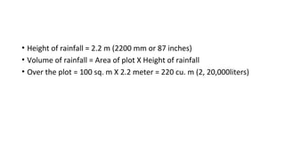
• Height ofrainfall = 2.2 m (2200 mm or 87 inches)
• Volume of rainfall = Area of plot X Height of rainfall
• Over the plot = 100 sq. m X 2.2 meter = 220 cu. m (2, 20,000liters)
25.
Surface Runoff RainwaterHarvesting
• Harvesting of surface runoff water and storage of the same into reservoirs
makes it available for use when required.
• In this method of collecting rainwater for irrigation, water flowing along the
ground during the rains will be collected to a tank below the surface of the
ground.
26.
RECHARGING OF GROUNDWATER AQUIFERS
• Various kind of recharge structures are possible which can ensure the rain water
percolates in the ground instead of draining away from the surface.
• While some structure promote the percolation of water through soil strata at the
shallow over (e.g. Recharge trenches, permeable pavements) other conducts
water to greater depths from where it joints to ground water. (E.g. recharge
wells)
• At many locations, existing features like wells, pits and tanks can be modifies to
be used as recharge structures, eliminating the needs to construct any new
structures.
• In numerable innovations and combination are these methods are possible.
27.
RECHARGE OF GROUNDWATER CAN BE DONE BY FOLLOWING TYPES:
• Bore wells/ Dug wells
• Recharge pits( Recharge wells)
• Soakaways (percolation pits)
• Recharge trenches
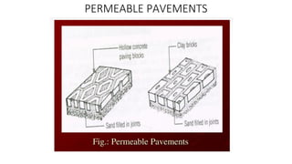
• Permeable surfaces
28.
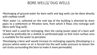
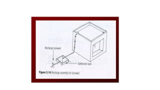
BORE WELLS/ DUGWELLS
•Recharging of ground water for bore wells and dug wells can be done directly
with rooftop runoff.
•Rain water i.e. collected on the roof top of the building is diverted by drain
pipes to a settlement or filtration tank, from which it flows into recharge well
(Bore well/ Dug well).
•If bore well is used for recharging, then the casing (outer pipe) of a bore well
should be preferably be a slotted or perforated pipe so that more surface area
is available for the water to percolate.
•Developing a bore well would increase its recharging capacity (Developing is a
process where water or air is forced into the well under pressure to loosen the
soil strata surrounding the bore to make it more permeable).
29.
• Any oldwell which has become this function can be used for recharging, since
the depth of such well is above the water level.
• Precautions are to be taken of physical matter in the runoff water like silt and
floating debris should not enter into the well. It may cause clogging a
recharging structure.
• It is preferred that dug wells/ bore wells used for recharging should be
shallower than the water table.
31.
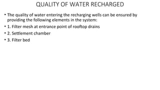
QUALITY OF WATERRECHARGED
• The quality of water entering the recharging wells can be ensured by
providing the following elements in the system:
• 1. Filter mesh at entrance point of rooftop drains
• 2. Settlement chamber
• 3. Filter bed
32.
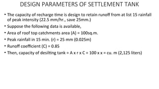
DESIGN PARAMETERS OFSETTLEMENT TANK
• Since the desilting time also acts as a buffer time, it is design in such a way
that it can retain the certain amount of rainfall, since the rate of recharge may
not be comparable with the rate of runoff.
• The capacity of the tank should be enough to retain runoff occurring from
conditions of peak rainfall intensity.
• E.g. In Mumbai, peak hourly rainfall is 90mm.( Based on 25years frequency).
• The rate of recharge in comparison to runoff is a critically factor however
accurate recharge rate is not available without delayed geo hydrological
studies.
33.
DESIGN PARAMETERS OFSETTLEMENT TANK
• The capacity of recharge time is design to retain runoff from at list 15 rainfall
of peak intensity (22.5 mm/hr., save 25mm.)
• Suppose the following data is available,
• Area of roof top catchments area (A) = 100sq.m.
• Peak rainfall in 15 min. (r) = 25 mm (0.025m)
• Runoff coefficient (C) = 0.85
• Then, capacity of desilting tank = A x r x C = 100 x x = cu. m (2,125 liters)
34.
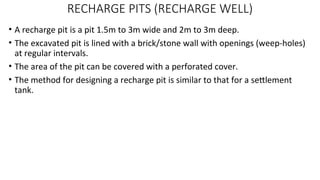
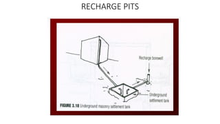
RECHARGE PITS (RECHARGEWELL)
• A recharge pit is a pit 1.5m to 3m wide and 2m to 3m deep.
• The excavated pit is lined with a brick/stone wall with openings (weep-holes)
at regular intervals.
• The area of the pit can be covered with a perforated cover.
• The method for designing a recharge pit is similar to that for a settlement
tank.
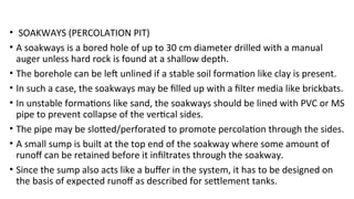
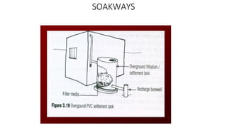
• SOAKWAYS (PERCOLATIONPIT)
• A soakways is a bored hole of up to 30 cm diameter drilled with a manual
auger unless hard rock is found at a shallow depth.
• The borehole can be left unlined if a stable soil formation like clay is present.
• In such a case, the soakways may be filled up with a filter media like brickbats.
• In unstable formations like sand, the soakways should be lined with PVC or MS
pipe to prevent collapse of the vertical sides.
• The pipe may be slotted/perforated to promote percolation through the sides.
• A small sump is built at the top end of the soakway where some amount of
runoff can be retained before it infiltrates through the soakway.
• Since the sump also acts like a buffer in the system, it has to be designed on
the basis of expected runoff as described for settlement tanks.
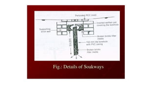
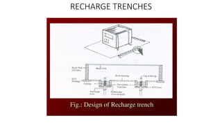
RECHARGE TRENCHES
• Rechargingthrough recharge trenches, recharge pits and soakways is simpler
compared to recharge through wells.
• Fewer precautions have to be taken to maintain the quality of rainfall runoff. For
this type of structure,
• i.e. no restriction on the type catchments from which water is to be harvested i.e.
both covered and uncovered catchments can be taped.
• A recharge trench is simply a continuous trench excavated in the ground and
refilled in the porous media like pebbles, boulders or brick bats.
• Recharge trench can be 0.5m to 1 m wide and 1 m to 1.5 m deep.
• The length of recharge trench is decided as per the amount of runoff.
• The recharge trench should be periodically clean m. is less permeable.
• To enhance the recharge rate the percolation pit can be provided at the bottom of
the trench.
40.
DESIGN OF RECHARGETRENCHES
• Required capacity of recharge tank = (A x r x C)
• D = (100 x x 0.85)
• 0.5
• = 4.25 cu. m (4,250 lit.)
• The voids ratio of the filler material varies with the kind of material used like
bricks beds, pebbles and gravels, voids ratio of 0.5 may be assume.
• The designing of recharge trench can be calculated by considering a fixed
depth and width.
DESIGN OF RECHARGETRENCH
• Methodology of design of recharge trench is similar to the design of
settlement tank the difference is that the water holding capacity of recharge
trench is less than its gross volume because it is filled with porous material.
• A factor of loose density (Voids ratio) of the medium as to be applied to the
equation.
• Using the same method as used for design of settlement tank.
• Area of rooftop catchment (A) = 100 sq.m.
• Peak rainfall in 16 min. (r) = 25 mm. (0.025 m.)
• Runoff coefficient (C) = 0.85
• Voids ratio (D) = 0.5 (Assumed)
43.
PERMEABLE SURFACES
• Unpaved(uncovered) surfaces have a greater capacity of retaining rain water
on surface.
• Patch of grass would retain a large proportion of the rain water falling on it,
yielding only % as runoff. The maximum amount of water can be retained on
such surface will naturally percolate in the ground.
• This type of surfaces contributes the natural recharge of ground water.
• If the harvested water is used direct uses or for recharging the ground water,
it is most important to assure that the rain water is collected is filled from any
pollutant that might be added to the rain water form the atmosphere or the
catchments.
44.
• PERMEABLE SURFACES
•Unpaved (uncovered) surfaces have a greater capacity of retaining rain water on surface.
• Patch of grass would retain a large proportion of the rain water falling on it, yielding only
% as runoff. The maximum amount of water can be retained on such surface will
naturally percolate in the ground.
• This type of surfaces contributes the natural recharge of ground water.
• If the harvested water is used direct uses or for recharging the ground water, it is most
important to assure that the rain water is collected is filled from any pollutant that might
be added to the rain water form the atmosphere or the catchments.
• while polluted water directly used for consumption would have a immediate impact on
health, polluted water recharge into the ground would cause long-term problem of
aquifer pollution.
• Damage done to aquifers by recharging by polluted water is permanent damage. Some
of the precaution measures have been summarized.