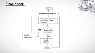
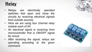
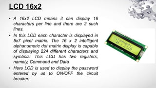
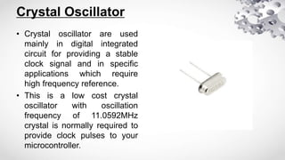
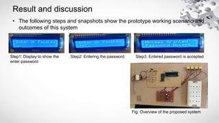
Secure Feeder Operation in Radial
Distribution System
Guided by
Mr. Lokesh kumar yadav
Content:
• Introduction
• Problem overview
• Literature survey
• Problem formulation
• Hardware components
• Results and discussion
• Conclusion
• References
Objective
• The main objective of this project is to secure
operation of distribution feeder as well as
provide safety to electrical lineman with the
help of password based circuit breaker.
Overview
• Nowadays, it is observed that fatal electrical accidents to the
lineman are increasing during the electric line repairing due to
lack of communication and co-ordination between the
maintenance staff and the electric sub-station staff.
• This project is designed to control the fatal elecrical accidents
and provides safety to the lineman during maintenance with
the help of password based circuit breaker.
• This system is fully controlled by microcontroller and matrix
keypad for entering password.
Literature Survey:
1. Athira P Nair, Josephin J, Anjana A S, Athira C P, Sebin J Olickal “ELECTRIC LINE MAN
SAFETY SYSTEM WITH OTP BASED CIRCUIT BREAKER”.
 Contribution of the paper: The electric line man safety system is designed to control a circuit breaker
with help of a password only. OTP generation and OTP verification are the major tasks involved in this
system. OTP generation is the main attraction of this project. It provides a new approach to the security
of the lineman and completely eliminates the accidents to the lineman due to electric shock during the
electric line repair.
 Scope: Using wireless communication this system can be operated from other areas besides the
substation such as on the transformer. The SCADA is a system used in the communication channels to
help easy troubleshoot to locate the fault location directly and the line man can easily rectify it.
2. Pramod M. Murari, Mahabal V. Kinnerkar, Prashant S. Koppa, Vishal S. Kamble, Rashmitha R. Mendan
“Electric Line Man Safety with Password Based Circuit Breaker and Intimation of HT Wire Sag
using GSM”
 Contribution of the paper: It can work on a single given known password Whenever the HT wire sag is
higher than the predetermined range/value then ultrasonic sensor sends a message to the substation
through GSM and intimates the operator about the trouble occurred. PIR sensor provides safety to
human/animal by sensing their presence and alerting through a buzzer.It can be concluded that the
proposed system can be used as an effective application in the present working system and provides
safety to lineman and alsocorrective measures can be taken after HT wire sag intimation.
 Scope:Instead of GSM 300 we can use GSM 900 which can be connected to IOT (internet of things).
By using IOT we can operate the relays from any area as we can directly connect to the server.
Wireless ultrasonic and PIR sensors can be also used. We can use SCADA system, to help easy
trouble shoot, to identify the fault location directly and line man can easily rectify it .we can also use
EPROMS that can be interfaced to system so the circuit breaker cannot only operate from the
substation ,but also from other location through wireless communication.
3. S.P. Achrekar, Shubham Jadhav, Praful Gurav, Makrand Rawool, Kaushal Manjrekar “OTP CIRCUIT
BREAKER FOR LINE MAN SAFETY AND MAINTAINANCE”
 Contribution of the paper: The electric line man safety system is designed to control a circuit breaker
with help of a password only. OTP generation and OTP verification are the major tasks involved in this
system. OTP generation is the main attraction of this project. It provides a new approach to the security
of the lineman and completely eliminates the accidents to the lineman due to electric shock during the
electric line repair.
 Scope: Using wireless communication this system can be operated from other areas besides the
substation such as on the transformer. The SCADA is a system used in the communication channels to
help easy troubleshoot to locate the fault location directly and the line man can easily rectify it.
Block Diagram
Power
supply
Keypad
MICROCONTROLLER
89S52
LCD 16x2
Relay 1
Relay 2
Relay 3
Relay 4
Load 1
Load 2
Load 3
Load 4
Flow chart:
Hardware Components
1. Microcontroller 89S52
2. Relay (4)
3. LCD 16x2
4. Keypad
5. PCB Board
6. Connecting Wires
7. Crystal Oscillator
Microcontroller 89S52
• A microcontroller is a small computer on a single
integrated circuit. A microcontroller contains one or more
CPUs along with memory and programmable input/output
peripherals.
• Microcontroller are used in automatically controlled
devices, such as automobile engine control system,
remote control,toys and other embedded systems.
• In this project 8bit microcontroller is used(AT89S52).
• The AT89S52 comes from the popular 8051 family of
Atmel Microcontrollers. It is an 8-bit CMOS microcontroller
with 8K as Flash memory and 256 bytes of RAM. Since it
is similar to the trust worthy 8051 architecture, these
microcontrollers are as per industry standard. It has 32
I/O pins comprising of three 16-bit timers, external
interrupts, full-duplex serial port, on-chip oscillator and
clock circuitry.
Pins to be used
1 to 7:- Keypad
18 to 19:- Crystal oscillator 11.059MHz
21 to 24:- Relays
32 to 39:- LCD
Relay
• Relays are electrically operated
switches that open and close the
circuits by receiving electrical signals
from outside sources.
• Here we are using four channel relay
module each of 5V.
• An electrical signal is receiving from
microcontroller that is ON/OFF signal
for circuit.
• After receiving the signal, relays are
operating according to the given
command.
LCD 16x2
• A 16x2 LCD means it can display 16
characters per line and there are 2 such
lines.
• In this LCD each character is displayed in
5x7 pixel matrix. The 16 x 2 intelligent
alphanumeric dot matrix display is capable
of displaying 224 different characters and
symbols. This LCD has two registers,
namely, Command and Data
• Here LCD is used to display the password
entered by us to ON/OFF the circuit
breaker.
Matrix Keypad
• Keypad is used as an input device to read
the key pressed by the user and to
process it.
• A 4x4 keypad has a total of 8 connections,
where 4 of them are connected to the
column and the remaining rows of the
matrix of switches.
• Here we are using 4x4 keypad to enter the
password.
Crystal Oscillator
• Crystal oscillator are used
mainly in digital integrated
circuit for providing a stable
clock signal and in specific
applications which require
high frequency reference.
• This is a low cost crystal
oscillator with oscillation
frequency of 11.0592MHz
crystal is normally required to
provide clock pulses to your
microcontroller.
Result and discussion
• The following steps and snapshots show the prototype working scenario and
outcomes of this system
Step1: Display to show the
enter password
Step2: Entering the password Step3: Entered password is accepted
Fig: Overview of the proposed system
Conclusion:
 The project titled “SECURE OPERATION FEEDER IN RADIAL DISTRIBUTION
SYSTEM” gave the following conclusions:
• It can work on given known password.
• The password to operate can be changed and system can be operated
efficiently with the changed password.
• It gives no scope of password stealing.
• It ensures the line man safety.
• There is also a provision of changing the password by changing in the
code.
Reference:
1. “Password based circuit breaker using Aurdino” , IJRET volume.08
Issue 06 June 2021
2. “Password based circuit breaker”, IJRASET volume.06 Issue 04 April
2018
3. “The electric lineman Safety using a new concept of OTP” , IJRET
volume.04 Special Issue 03 April 2015
4. “Lineman Safety”, IJIREEICE Volume.09 Issue 01 January 2021
THANK YOU

Radial Distribution System presentation 1.pptx

  • 1.
    Secure Feeder Operationin Radial Distribution System Guided by Mr. Lokesh kumar yadav
  • 2.
    Content: • Introduction • Problemoverview • Literature survey • Problem formulation • Hardware components • Results and discussion • Conclusion • References
  • 3.
    Objective • The mainobjective of this project is to secure operation of distribution feeder as well as provide safety to electrical lineman with the help of password based circuit breaker.
  • 4.
    Overview • Nowadays, itis observed that fatal electrical accidents to the lineman are increasing during the electric line repairing due to lack of communication and co-ordination between the maintenance staff and the electric sub-station staff. • This project is designed to control the fatal elecrical accidents and provides safety to the lineman during maintenance with the help of password based circuit breaker. • This system is fully controlled by microcontroller and matrix keypad for entering password.
  • 5.
    Literature Survey: 1. AthiraP Nair, Josephin J, Anjana A S, Athira C P, Sebin J Olickal “ELECTRIC LINE MAN SAFETY SYSTEM WITH OTP BASED CIRCUIT BREAKER”.  Contribution of the paper: The electric line man safety system is designed to control a circuit breaker with help of a password only. OTP generation and OTP verification are the major tasks involved in this system. OTP generation is the main attraction of this project. It provides a new approach to the security of the lineman and completely eliminates the accidents to the lineman due to electric shock during the electric line repair.  Scope: Using wireless communication this system can be operated from other areas besides the substation such as on the transformer. The SCADA is a system used in the communication channels to help easy troubleshoot to locate the fault location directly and the line man can easily rectify it. 2. Pramod M. Murari, Mahabal V. Kinnerkar, Prashant S. Koppa, Vishal S. Kamble, Rashmitha R. Mendan “Electric Line Man Safety with Password Based Circuit Breaker and Intimation of HT Wire Sag using GSM”  Contribution of the paper: It can work on a single given known password Whenever the HT wire sag is higher than the predetermined range/value then ultrasonic sensor sends a message to the substation through GSM and intimates the operator about the trouble occurred. PIR sensor provides safety to human/animal by sensing their presence and alerting through a buzzer.It can be concluded that the proposed system can be used as an effective application in the present working system and provides safety to lineman and alsocorrective measures can be taken after HT wire sag intimation.
  • 6.
     Scope:Instead ofGSM 300 we can use GSM 900 which can be connected to IOT (internet of things). By using IOT we can operate the relays from any area as we can directly connect to the server. Wireless ultrasonic and PIR sensors can be also used. We can use SCADA system, to help easy trouble shoot, to identify the fault location directly and line man can easily rectify it .we can also use EPROMS that can be interfaced to system so the circuit breaker cannot only operate from the substation ,but also from other location through wireless communication. 3. S.P. Achrekar, Shubham Jadhav, Praful Gurav, Makrand Rawool, Kaushal Manjrekar “OTP CIRCUIT BREAKER FOR LINE MAN SAFETY AND MAINTAINANCE”  Contribution of the paper: The electric line man safety system is designed to control a circuit breaker with help of a password only. OTP generation and OTP verification are the major tasks involved in this system. OTP generation is the main attraction of this project. It provides a new approach to the security of the lineman and completely eliminates the accidents to the lineman due to electric shock during the electric line repair.  Scope: Using wireless communication this system can be operated from other areas besides the substation such as on the transformer. The SCADA is a system used in the communication channels to help easy troubleshoot to locate the fault location directly and the line man can easily rectify it.
  • 7.
    Block Diagram Power supply Keypad MICROCONTROLLER 89S52 LCD 16x2 Relay1 Relay 2 Relay 3 Relay 4 Load 1 Load 2 Load 3 Load 4
  • 8.
  • 9.
    Hardware Components 1. Microcontroller89S52 2. Relay (4) 3. LCD 16x2 4. Keypad 5. PCB Board 6. Connecting Wires 7. Crystal Oscillator
  • 10.
    Microcontroller 89S52 • Amicrocontroller is a small computer on a single integrated circuit. A microcontroller contains one or more CPUs along with memory and programmable input/output peripherals. • Microcontroller are used in automatically controlled devices, such as automobile engine control system, remote control,toys and other embedded systems. • In this project 8bit microcontroller is used(AT89S52).
  • 11.
    • The AT89S52comes from the popular 8051 family of Atmel Microcontrollers. It is an 8-bit CMOS microcontroller with 8K as Flash memory and 256 bytes of RAM. Since it is similar to the trust worthy 8051 architecture, these microcontrollers are as per industry standard. It has 32 I/O pins comprising of three 16-bit timers, external interrupts, full-duplex serial port, on-chip oscillator and clock circuitry.
  • 12.
    Pins to beused 1 to 7:- Keypad 18 to 19:- Crystal oscillator 11.059MHz 21 to 24:- Relays 32 to 39:- LCD
  • 13.
    Relay • Relays areelectrically operated switches that open and close the circuits by receiving electrical signals from outside sources. • Here we are using four channel relay module each of 5V. • An electrical signal is receiving from microcontroller that is ON/OFF signal for circuit. • After receiving the signal, relays are operating according to the given command.
  • 14.
    LCD 16x2 • A16x2 LCD means it can display 16 characters per line and there are 2 such lines. • In this LCD each character is displayed in 5x7 pixel matrix. The 16 x 2 intelligent alphanumeric dot matrix display is capable of displaying 224 different characters and symbols. This LCD has two registers, namely, Command and Data • Here LCD is used to display the password entered by us to ON/OFF the circuit breaker.
  • 15.
    Matrix Keypad • Keypadis used as an input device to read the key pressed by the user and to process it. • A 4x4 keypad has a total of 8 connections, where 4 of them are connected to the column and the remaining rows of the matrix of switches. • Here we are using 4x4 keypad to enter the password.
  • 16.
    Crystal Oscillator • Crystaloscillator are used mainly in digital integrated circuit for providing a stable clock signal and in specific applications which require high frequency reference. • This is a low cost crystal oscillator with oscillation frequency of 11.0592MHz crystal is normally required to provide clock pulses to your microcontroller.
  • 17.
    Result and discussion •The following steps and snapshots show the prototype working scenario and outcomes of this system Step1: Display to show the enter password Step2: Entering the password Step3: Entered password is accepted Fig: Overview of the proposed system
  • 18.
    Conclusion:  The projecttitled “SECURE OPERATION FEEDER IN RADIAL DISTRIBUTION SYSTEM” gave the following conclusions: • It can work on given known password. • The password to operate can be changed and system can be operated efficiently with the changed password. • It gives no scope of password stealing. • It ensures the line man safety. • There is also a provision of changing the password by changing in the code.
  • 19.
    Reference: 1. “Password basedcircuit breaker using Aurdino” , IJRET volume.08 Issue 06 June 2021 2. “Password based circuit breaker”, IJRASET volume.06 Issue 04 April 2018 3. “The electric lineman Safety using a new concept of OTP” , IJRET volume.04 Special Issue 03 April 2015 4. “Lineman Safety”, IJIREEICE Volume.09 Issue 01 January 2021
  • 20.