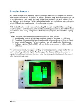
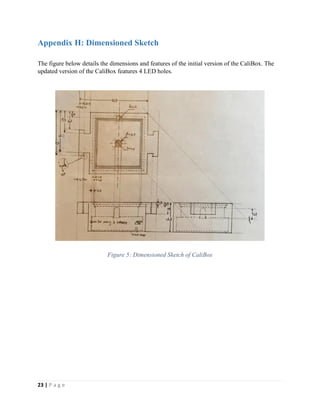
The document presents the design of a CaliBox to simplify the calibration process for Psylotech's μTS imaging system, including a box to hold the calibration target, supplemental micrometer extender, and instructions for construction and use. It summarizes user research, design concept and rationale, and proposes future developments to improve the prototype.
Productivity Studies of Ultra High Density (UHD) Stitching Processidescitation
This paper focuses on Ultra High Density (UHD) stitching process of connectors,
where the company relies on 100% manual inspection in UHD connectors. Based on
historical data on production of UHD connectors, typically labour cost involved in
inspection and testing is around 15% of the total manufacturing cost. This poses both
challenges and opportunities for improvement in the bottleneck process, which is the
inspection process. The female connectors quantity produced is on the average of 2000
parts/shift. It takes around 47 sec of visual inspection per connector and around 2.89 sec per
piece for go-gauge inspection. Considering these factors, the objectives of the study was to
understand the whole process in its entirety and then use this knowledge to re-organize the
stages staring from the automatic stitching process. By using process improvement tools of
time study, methods and process mapping, a process re-orientation and re-organization has
been carried out. This resulted in not only reduction of time of inspection and testing of the
connectors, but also the piece inspection process reduced from an average total time of
112.59 sec to 86.15 sec. Overall improvement was also increased from 56% to 79.5%.
Optez pour une solution de gestion Microsoft complète, fiable et conviviale,...PRODWARE
A l’heure de la transformation numérique, la productivité doit être réinventée. Les processus métiers intégrés au fonctionnement global de l’entreprise. Tour d’horizon des outils @Microsoft, notre partenaire.
Presented at Big Android BBQ 2015
Hurst Convention Center, Hurst Texas
This talk will cover Fragments in detail by comparing and contrasting them to something we know well, Activities. We will also cover examples and use cases. Fragments: Why, How, and What For? is targeted toward developers who may not have had a lot of experience using Fragments and those who want to understand them better. Why did Google introduce Fragments? Aren’t Activities enough? How do Fragments work? What For? Example and use cases such as Fragment reuse, single pane vs multi-pane, ViewPager, NavigationDrawer and DialogFragment.
I have taken coaching from NARESH INSTITUTE for CRT (Campus Recruitment Training). In these videos, I have explained all the questions with answer and how to approach for the question etc, in the same manner how they have taught to me at the time of training. Hope u like it.
The Indian Dental Academy is the Leader in continuing dental education , training dentists in all aspects of dentistry and
offering a wide range of dental certified courses in different formats.for more details please visit
www.indiandentalacademy.com
LEAN OPERATIONS, Review the literature giving detailed examples of where within
industry Lean has been applied, the strategies followed when
implementing, the benefits achieved and whether there are any
lessons to be learned.
Clap control home automation (clap switch)VinaOconner450
Clap control home automation (clap switch)
Need INTRODUCTION:
-
Project(s) that are selected during group meetings in class
Fantastic 4 Projects
1) Ride Suitcase
2) Second hand market service
3) Intermediary agencies for overseas study
4) Clap control home automation (clap switch)
5) Bioelectrical Impedance method for dengue fever recognition without using a blood sample
6) Finger print door lock (Arduino Project)
7) College Radio
8) Bike share
9) Seat belt safety alarm
10) Biometric Attendance
11) Drowsy alarm in Car
12) Image albums service
However, the project Clap control home automation (clap switch), Heart Beat Sensor at home, Second hand market service, and Image albums service are the projects we choose 4 out of 12 projects, and they earn the most “Positive” counts during the factors evaluate process. And given all factors and structures that meet the requirements of the project, we decided to choose Clap control home automation (clap switch) as our final project.
2. Project selection criteria that were employed. Please explain why such criteria
Our group's standard for selected projects is to provide customers with more convenient and fast life modes. The fast lifestyle is the mainstream at present. While saving time, the consideration benchmark for us to lock in project goals in different fields is to provide all potential customers with better service and experience by taking advantage of the fields involved in our project. Our product Clap control home automation (Clap switch), Heart Beat Sensor at home, Second-hand market service, and Image albums service are all based on the consideration of providing users with a more convenient and effective lifestyle. Standards are developed by considering the rationality of the product and the requirements of the public. We calculate the positive index of the product to determine whether the product can meet the needs of customers. Based on the final comprehensive score, the project Clap control home automation (Clap switch) has the highest comprehensive score, and its practicability and feasibility are most suitable for the purpose and goal of R&D project.
3. Show the selection procedure(s) you followed in selecting the project(s) among other projects
When the target project is further subdivided and the most beneficial project is selected, we will conduct internal screening and vote selection by team members, and compare the results calculated by weight score mode. There may be some differences in opinions, because each group member thinks differently. However, in the calculation process of weighing factors and weight score method, the final selected project must be reasonable and fair. Each project will be measured independently against standard requirements.
4. Share the experience in selecting projects in your team. Were there any conflicts or any challenges during project selection? How did you resolve the conflicts and/or the challenges?
In the process of choosing a ...
Demystifying Designing for ‘X’ by ProTek Medical ProtekMedical
http://www.protek.ie/
Annette Carty-Mole B.Eng (Hons)
Design Engineer, ProTek Medical
When a company is given the task of designing a
new product or redesigning an existing product, it
is important to keep in mind the three main goals
of cost, quality and speed. These goals can be
further split into more quantitative criteria which
are relevant throughout the product’s life cycle.
Designing for manufacture and assembly are typical
examples of two criteria which will have a large
impact on the cost, quality and speed at which the
product is developed. The methodology of design
that meets an all-encompassing range of criteria is
known as designing for ‘X’.
Overview on Kanban Methodology and its ImplementationLaukik Raut
Kanban methodology is very significant
philosophy which plays an important role in many
production units. In this paper Kanban methodology has
been reviewed and has been implemented on „Swing Lever
Assembly‟ of the Bajaj Steels Pvt. Ltd Nagpur. The Kanban
system involves the selection of two important parameters
i.e. the lot size and the numbers of Kanban used in the
process. The main objective of Kanban system is to
maximize the productivity of a unit and this is done by
reducing the idle time of the process. Kanban system is a
very cost efficient process if applied in proper manner.
RUNNING HEAD New Castle County Library System.1RUNNING HEAD.docxtoltonkendal
RUNNING HEAD: New Castle County Library System.
1
RUNNING HEAD:
12
New Castle County Library system
Kriti Gangadhara
Neha Bandaru
Wilmington University
IST 7020 Analysis, Modeling and Design
Professor: Harold Lowe
Date: 10/03/2016
Table of Contents
31.Executive Summary
31.1.Issue
31.2.Anticipated Outcomes
31.3.Recommendation
31.4.Justification
32.Business Case Analysis Team
33.Problem Definition
33.1.Problem Statement
33.2.Organizational Impact
43.3.Technology Migration
44.Project Overview
44.1.Project Description
44.2.Goals and Objectives
44.3.Project Performance
44.4.Project Assumptions
44.5.Project Constraints
44.6.Major Project Milestones
55.Cost Benefit Analysis
56.Approvals
1. Executive Summary
Usually, this section is completed last after all other sections of the business case have been written. This is because the executive summary is exactly that, a summary of the detail that is provided in subsequent sections of the document. This section should provide general information on the issues surrounding the business problem and the proposed project or initiative created to address it.
1.1. Issue
We are updating the existing software for New castle county Library book transactions. The issue with the existing software is that, people are not able to place hold on the books that they were willing to borrow from the library.
1.2. Anticipated Outcomes
· After the new feature is developed, people will be able to put hold on the books they want to borrow.
· We are including a feature where in, if a particular book is not available in the NCC library, it can search in the neighboring county libraries.
· Once the book is tracked, it will be shipped to the NCC library and put on hold.
· The person who puts the book on hold will have 10 days within which he could visit the library and collect it.
· If the book is not collected within 10 days, the hold placed on the book will be removed.
1.3. Recommendation
To achieve the desired results, we are following the below approach in our project:
· The requirements are obtained from the client by the system analyst and conveyed to the programming team.
· Once the Requirements are clear, the development starts in the development instance. This is tested in the testing environment where in dummy data is used.
· Once the tested prototype is presented to the client, if it is approved, the system is migrated to the production. If not, further development is carried out in order to satisfy the client’s requirements.
· Once the system is migrated to the production, it is supported there by the support team in order to make sure the system is stable. And thus signing off the project from the client.
1.4. Justification
This project makes it easier to track the transactions of the books, and also to make sure the person who puts hold on a book first will be made available of the book.
Also, the added feature of bringing the book from the neighboring county libraries helps to provide an excel ...
IOP Conference Series Materials Science and EngineeringPA.docxvrickens
IOP Conference Series: Materials Science and Engineering
PAPER • OPEN ACCESS
Improvement of the customer satisfaction through
Quality Assurance Matrix and QC-Story methods:
A case study from automotive industry
To cite this article: G M Sicoe et al 2017 IOP Conf. Ser.: Mater. Sci. Eng. 252 012045
View the article online for updates and enhancements.
Related content
Service quality that improves customer
satisfaction in a university: a case study in
Institut Teknologi Indonesia
L Theresia and R Bangun
-
Survival analysis for customer satisfaction:
A case study
M A Hadiyat, R D Wahyudi and Y Sari
-
Evaluation of User Satisfaction in Public
Residential Housing - A Case Study in the
Outskirts of Naples, Italy
Fabiana Forte and Yvonne Russo
-
This content was downloaded from IP address 154.59.124.91 on 18/02/2020 at 18:37
https://doi.org/10.1088/1757-899X/252/1/012045
http://iopscience.iop.org/article/10.1088/1757-899X/277/1/012059
http://iopscience.iop.org/article/10.1088/1757-899X/245/1/012029
http://iopscience.iop.org/article/10.1088/1757-899X/245/5/052063
1
Content from this work may be used under the terms of the Creative Commons Attribution 3.0 licence. Any further distribution
of this work must maintain attribution to the author(s) and the title of the work, journal citation and DOI.
Published under licence by IOP Publishing Ltd
1234567890
CAR-2017 IOP Publishing
IOP Conf. Series: Materials Science and Engineering 252 (2017) 012045 doi:10.1088/1757-899X/252/1/012045
Improvement of the customer satisfaction through Quality
Assurance Matrix and QC-Story methods: A case study from
automotive industry
G M Sicoe1, N Belu1, N Rachieru1 and E V Nicolae2
1Department of Manufacturing and Industrial Management, Faculty of Mechanics and
Technology, University of Piteşti, 110040 Pitesti, Targu din Vale Street, no. 1, Argeş,
Romania
2Automotive and Transport Department, Faculty of Mechanics and Technology,
University of Piteşti 110040 Pitesti, Targu din Vale Street, no. 1, Argeş, Romania
Abstract. Presently, in the automotive industry, the tendency is to adapt permanently to the
changes and introduce the market tendency in the new products that leads of the customer
satisfaction. Many quality techniques were adopted in this field to continuous improvement of
product and process quality and advantages were also gained. The present paper has focused on
possibilities that offers the use of Quality Assurance Matrix (QAM) and Quality Control Story
(QC Story) to provide largest protection against nonconformities in the production process,
throughout a case study in the automotive industry. Ther ...
1. 1 | P a g e
Prepared for:
Mr. Charles Spellman
Psylotech
May 18, 2016
Submitted by:
Joycelyn Dong, Kun Lei, Vickie Li, John Rosebrough
Section 6, Team 1 Spring 2016
Professors Douglas Wills and Jeanine Casler
Design, Thinking, and Communication Program
McCormick School of Engineering and Applied Science
Northwestern University
Evanston, IL 60208
2. 2 | P a g e
Table of Contents
Executive Summary....................................................................................................................................4
Introduction.................................................................................................................................................5
Users and Requirements.............................................................................................................................6
Design Concept and Rationale...................................................................................................................7
Future Development ...................................................................................................................................9
Conclusion .................................................................................................................................................10
References..................................................................................................................................................11
Appendix A: Secondary Research Summary .........................................................................................12
Appendix B: Project Definition ...............................................................................................................13
Appendix C: Client Interview Summary................................................................................................15
Appendix D: User Observation Summary..............................................................................................17
Appendix E: User Testing Report ...........................................................................................................18
Appendix F: Performance Testing Report .............................................................................................21
Appendix G: Safety Analysis ...................................................................................................................22
Appendix H: Dimensioned Sketch...........................................................................................................23
Appendix I: Instructions for Construction.............................................................................................24
Appendix J: Instructions for Use.............................................................................................................26
Main Report
Appendices
3. 3 | P a g e
Figures and Tables
Figure 1: Target and Diffuser Ridges ......................................................................................... 7
Figure 2: Testing of Target Holder Mockup ............................................................................ 18
Figure 3: Rail Mockup................................................................................................................ 18
Figure 4: Double Stage Mockup................................................................................................ 19
Figure 5: Dimensioned Sketch of CaliBox................................................................................ 23
Figure 6: Stage with Micrometer Extender.............................................................................. 26
Figure 7: Configuration of Stage and Psylotech Frame.......................................................... 26
Figure 8: CaliBox in the dog-bone shaped grips of Psylotech's frame................................... 27
Table 1: Requirements and Specifications for Prototype ....................................................... 13
Table 2: Summary of User Testing Results .............................................................................. 19
Table 3: FMEA Safety Analysis................................................................................................. 22
Table 4: Materials for Construction of Prototype ................................................................... 24
Figures
Tables
4. 4 | P a g e
Executive Summary
We were asked by Charles Spellman, a product manager at Psylotech, a company that provides
novel high resolution sensor technology, to design a product to assist with the calibration process
of their µTS system. Their current process is cumbersome and inefficient. With guidance from
Mr. Spellman, we designed the CaliBox, a lighted calibration box that holds the speckled pattern
target. CaliBox is also supplemented with a micrometer extender.
With the CaliBox, the overall process of using the µTS device is simplified. There is no longer a
need to assemble a calibration configuration and also a testing configuration. The calibration can
easily be done in the testing configuration. The CaliBox also improves the current back lighting
system.
CaliBox meets the following requirements requested by our client and user:
1. Simplification of entire process: Decreasing the amount of time used for calibration
2. Ease of use: The shape of the box allows for quick addition and removal from the frame
3. Improvement of accuracy: The box is stationary and will not allow the glass to move
4. Sufficient Lighting: The four LEDs will provide the correct amount of light needed for
calibration
For future improvements, we suggest searching for a micrometer on the current market that is at
least 4 inches long and that is digital. We also suggest that the current lithium ion battery is
replaced with a lithium ion battery that has a better charging signal so that a user is forewarned
when charging is necessary.
5. 5 | P a g e
Introduction
Imaging distortion is a common problem in the material testing process. Distortion can originate
from the alignment of optics, shape of lenses, human errors, etc. Such distortions may lead to
inaccurate calibration of the optical system, and result in wrong measurements for the tested
materials. Reducing imaging distortion is crucial to ensure correct measurements for the
materials and the safety of engineering configurations using the tested materials.
The common way to address this problem is to improve the precision of optical and calibration
devices (see Appendix A: Secondary Research Summary). However, this can be very costly as
precision improves. We aim to solve the problem from a different approach: reduce imaging
distortion by simplifying the calibration and testing process to minimize human errors (see
Appendix B: Project Definition). We hope that this simplification may also improve the
efficiency of the entire material testing process.
The device we designed, the CaliBox, consists of two parts: a speckled pattern target holder that
simplifies the calibration process and a knob extender that provides easier turnings for the
calibration stage.
This report explains the client’s requirement and specifications for the design, a detailed
explanation of the design and rationale, and a discussion of possibilities for future development.
6. 6 | P a g e
Users and Requirements
Introduction
For this design, the primary users include employees of Psylotech and those who purchase their
product. The main stakeholder is Psylotech and the main requirements for the design include
accuracy, simplification, safety, ease of use, and ease of maintenance.
Main Users of the Design
1. Users of the µTS system
The µTS system can be used in different workplaces but can be mainly found in labs.
This system is usually used to characterize materials although it has many other
applications.
2. Employees of Psylotech
The employees of Psylotech are both users and clients for this project. We can list
Psylotech as a user because in addition to distributing the µTS system they also offer
services to test individual materials. In other words, Psylotech will also be users since
they are constantly operating their own device.
Stakeholders
The main stakeholder is Psylotech, which hopes to improve their µTS system (see Appendix C:
Client Interview Summary).
Design Requirements
1. Improvement in accuracy
The user wanted a product that would improve the accuracy of the testing and calibration.
2. Simplification of process
The user wanted a product that would simplify the overall process of testing. In the
original process involved.
3. Safety
The user wanted a product that does not damage the speckled pattern glass or the µTS
system.
4. Durability and easy to maintain
The user wanted a product that is sturdy so it doesn’t break down or require maintenance.
7. 7 | P a g e
Design Concept and Rationale
Design Overview
The CaliBox is designed to allow users of Psylotech’s frame and testing system to complete
calibration for a given setup rapidly, without disassembling the testing apparatus. This will
greatly streamline the process of calibration and allow for a more pleasant user experience. The
CaliBox is made up of 3 main components: the box, diffuser, and backlighting. The CaliBox,
composed of these three components, allows for users to go through the calibration process
without worry of distortion error. (See Appendix D: User Observation Summary, Appendix E:
User Testing Report, Appendix F: Performance Testing Report, and Appendix G: Safety
Analysis)
Design Components: Specifications and Rationale
1) 3D printed body
The box consists of a main body and a base. The base is screwed into the body to allow for
removal for maintenance on internal components of the box. The body of the CaliBox is 3D
printed from PLA plastic to ensure that the structure isn’t too brittle. This is necessary because
the testing frame is extremely rigid, and a stiffer material might snap if the frame is adjusted at
all while holding the CaliBox. The sides of the CaliBox have two small dog-bone shaped
extensions, designed to match the sample holders of the same shape on the testing frame. The
dog-bone shaped handles allow for the device to be inserted directly into the testing frame so that
the necessary translations can be completed without disassembling the testing apparatus (see
Appendix H: Computer-aided Drawings, Appendix I: Instructions for Construction, and
Appendix J: Instructions for Use).
2) Target and diffuser holders
The top of the CaliBox has two small ridges taken out of the plastic. The lower and slightly
smaller ridge is for holding a plastic diffuser, and the higher ridge is for holding the calibration
target. The ridge for the target has an additional semicircular cutout to allow for easy removal of
the calibration target despite the extremely tight fit. In figure X, the target and diffuser ridges are
clearly labeled.
Figure 1: Target and Diffuser Ridges
8. 8 | P a g e
3) Backlighting
The CaliBox uses 4 small green LEDs as backlighting for the calibration target. Green was
chosen to provide a single wavelength of light which will give more accurate calibration results.
The LEDs are controlled by two external switches: A toggle switch for turning the lights on and
off directly, and a dimmer switch for adjusting the brightness of the lights. A small diffuser
filter is also placed above the LEDs in order to ensure that the light is more evenly distributed
over all sections of the calibration target. The lights are powered by a small rechargeable lithium
ion battery pack with an externally accessible charging port to allow users to easily recharge the
device.
4) Micrometer Extender
The micrometer extender extends the current micrometer by extending the end that sticks into the
stage.
9. 9 | P a g e
Future Development
We see potential for further development in the following areas.
CaliBox
Due to time and cost constraints, we chose to use the 150 mAh lithium ion batteries as the
power source for LEDs, and screws for back cover connection. We see potential in using
lithium batteries with larger capacities and with proper modification for monitoring
remaining power in order to prevent over-discharging. This would require us to conduct
further research about lithium batteries and perform multiple tests to determine the
optimal solution. We also hope to modify the rear cover connection and use a structure
similar to the rear cover of remote controls in the future.
Micrometer Extender
Due to time limits, we chose to extend the micrometer that comes standard with Thorlabs
XYR stages. We see potential in finding a commercial micrometer that includes features
such as digital monitor and a length of at least 4 inches. This length was determined from
the current configuration of the system and the challenge it produces for users to reach
the micrometer.
10. 10 | P a g e
Conclusion
During the client meetings and testing sessions, our team identified the essential features that the
client wanted - simple-to-use and able to reduce human errors in the imaging and testing process.
We built the CaliBox (with supplemental knob extender) which both simplified the entire
calibration and testing process, therefore reducing human errors in imaging distortion.
We believe that the CaliBox (with supplemental knob extender) solution will address the client’s
needs. We hope that, with the CaliBox and the Extender, our client and future users can not only
gain more precise results from the calibration and imaging processes, but also improve efficiency
of future tests.
11. 11 | P a g e
References
Correlated Solutions -“Using Microscope Distortion Correction in Vic-2D”
Psylotech- “Modular Under Microscope Mechanical Test System -µTS User Manual”
12. 12 | P a g e
Appendix A: Secondary Research Summary
At the beginning of our project, we conducted background research on terms and concepts
mentioned by our client, Charles Spellman of Psylotech, in his written description and first client
meeting. The project involves simplifying Psylotech’s imaging device and its process.
Our background research helped us begin to understand several aspects of the problem so that we
were better prepared for the client and user interview.
An overview of imaging
Psylotech has designed a testing frame to take images of materials being pulled on from each end
in order to better characterize them. A microscope with an attached camera takes images
continuously as this deformation is happening, and these are run through software that generates
a map of where the greatest movements and deformation lies. This information is used to gain a
greater understanding of the properties of a given material.
Calibration
Prior to imaging, the system must be calibrated to account for lens aberrations and defects. A
piece of glass with a speckled pattern sized specifically for a given objective lens is placed on the
stage. This is then moved 5 times to the right along the x-axis, back to the origin, and then 5
times upwards along the y-axis, with an image taken at each of these ten points and at the
origin. The calibration software then compares the images to find out the effects of a given lens
on imaging so that these effects can be ignored when actual imaging is done. This process must
be repeated each time the objective lens, and therefore zoom factor, is changed.
Imaging Setup
The imaging testbed is mounted on an optical table to allow for stability and precision. The
bottom layer is a stage that allows for sample movement on the X, Y, and rotational axes. Next
is an aluminum plate that reinforces the whole structure and allows for the mounting of the final
component, the testing frame. The testing frame has two slots for vice clamps to hold the ends of
a material sample in a “dog-bone” shape--thin midsection, wide at either end. These clamps can
be pulled apart from each other to deform and break apart the material sample, which is imaged
using an Olympus optical microscope with an attached digital camera or a standalone digital
camera, depending on the requirements for that imaging session.
Current solutions
Essentially, the current setup is extremely cumbersome. Although the calibration process is
reasonably fast, it does require the disassembly of most of the testing apparatus each time lenses
are changed on the microscope, in order to recalibrate. It also currently allows for a large
amount of human error as a result of the fact that the stage must be manually operated.
13. 13 | P a g e
Appendix B: Project Definition
Project name: CaliBox
Client: Mr. Charles Spellman of Psylotech
Team members: Joycelyn Dong, Kun Lei, Vickie Li, Alex Rosebrough
Date: May 26, 2016
Version: Three
Mission Statement: To develop a simple and repeatable method of setting up microscopy optics
and camera equipments to capture required images for the user with minimal distortion.
Project Description: Psylotech leverages high quality microscopy optics with digital cameras to
acquire images of materials in an effort to better characterize them for modeling and simulation.
While the optics are the highest quality available, the calibration process of the equipment
remains difficult to perform and therefore, error prone. This often causes unnecessary distortions
to occur. We would like to develop a simple and repeatable method to make the calibration
process simpler and more accurate.
Project Deliverables:
A functional prototype of a method that simplifies the calibration process.
Detailed instructions for the new calibration process.
Constraints:
Materials must not cost more than $100.
Must be completed before June 9, 2016.
Users/Stakeholders:
Engineers at Psylotech.
Users of the Psylotech microscopy optics equipment.
Table 1: Requirements and Specifications for Prototype
Requirements Specifications
Translation Accuracy
Must be able to support accurate
calibration under 1x to 50x
magnification
Method must allow users to translate
the speckled pattern glass on the X
and Y axis by 10 mm under the 1 x
scale and 220 microns under the 50x
scale
Provides a micrometer extender that
allows the user to turn the calibration
knob with ease and accuracy
14. 14 | P a g e
Lighting Support
Must have either front or back lighting
to allow for crisp images under the
microscope
Four green LEDs with diffuser filter
Ease of Use
Must allow for easy adjustments
Must allow for easy removal
Outer box design constructed using
plastic
Outer box design that fits directly into
the µTS device
15. 15 | P a g e
Appendix C: Client Interview Summary
We conducted our initial interview with our client, Mr. Charles Spellman, a product manager for
Psylotech, on Friday, April 8th
, 2016 from 2:45 p.m. to 4:10p.m., in the Psylotech office. All
group members were present. The purpose of the meeting was to learn more from Mr. Charles
Spellman about the optical system Psylotech uses, the main problems with current devices, the
requirements for our prototype, and users and potential specialists of the opetical system. This
appendix summarizes what we learned about the current devices, design problem, requirements,
and users.
Current Optical System
Our client demonstrated the components and usage of the current optical system Psylotech has:
The current device is composed of five parts: a microscope, a speckled pattern chip, an
XYR-stage, a plate and a frame Psylotech designed.
The microscope is used to capture image of the material tested;
the speckled pattern chip serves as the standard for calibrations;
the xyr-stage is used to move the speckled pattern chip around during calibrations;
the Psylotech plate serves as a support to the Psylotech frame and a connection between
the xyr-stage and the Psylotech frame;
the Psylotech frame is used to fix the materials tested under the microscope and to stretch
the material for testing purposes.
Usage of the optical system includes three steps:
1. Calibration of the microscope: using an LED backlight to illuminate the speckled
pattern chip, and manually moving the plate around using the xyr-stage to collect
eleven images for calibration.
2. Reassembling the optical system: disassembling the speckled pattern chip and
xyr-stage, and assembling the Psylotech frame, Psylotech plate, and xyr-stage one
on top of another.
3. Testing materials: inserting the material plate into the Psylotech frame,
illuminating the material with front light, stretching the material plate with the
frame, and capturing images needed.
Problems
Our client pointed out the issues and inadequacy regarding the current optical system:
According to the feedbacks Mr. Spellman receives, advanced users of the Psylotech
optical system find it difficult to use the system without disassembling the entire system,
a process that often takes around ten minutes to complete.
The switch between backlight (used in calibrations) and front light (used in material
testing) is cumbersome in the testing process; the Psylotech plate and frame also gets in
the way of backlighting.
It takes extra time and attention to tell the sides of the speckled pattern chip; only a
specific area of the speckled pattern chip is actually in use.
The Psylotech frame needs to be supported by a plate to remain stable, but the current
plate is merely long enough to provide the required support.
The calibration and testing process is error prone due to the manual repositions of the
speckled pattern chip and materials tested.
16. 16 | P a g e
Requirements
Our client identified these requirements and potential options for the design:
Ease of use
o The design should be easy for users to organize and operate.
o The design should accommodate the Psylotech frame during calibration.
Accuracy
o The xyr-stage and Psylotech frame needs to remain stable during calibrations and
testing.
o The plate needs to be long enough to provide support for the Psylotech frame.
o Low thermal fluctuation during calibration is needed.
o The repositions of the speckle pattern chip during calibration should be as
accurate as possible.
Specific features
o The design should allow the Psylotech frame to be fixed on one end, and free to
move on the other end.
o The design should ideally avoid reassembly of the Psylotech frame, and should
translate accurately.
Potential options worth consideration
o Attaching the speckled pattern chip to the Psylotech frame.
o Creating a new speckled pattern chip.
o Developing a new calibration system, optimally only involving front light to
avoid the light switch.
o Designing an automated system to perform reposition, calibration, and testing, if
time is sufficient.
o Incorporating a fixture on top of the Psylotech frame to attach the front light to
the frame.
Creativity
o The design should be creative and innovative.
Cost
o The prototype should ideally cost less than 500 dollars.
Users and Specialists
Our client pointed out the user group of the optical system and specialists we may reach out to:
Users of the design product are technicians within the material science field.
Specialists include:
o Correlated Solutions Company, which produces the scatter pattern chip and
suggests the use of backlight;
o Researchers of Clammp Lab at NU;
o Technicians in Misumi Company, which produces the Psylotech plate used in the
current optical system.
The interview provided crucial information for understanding the current optical system, the
problem, client requirements, and users. In light of this information, we will be brainstorming for
ideas that synthesize the requirements of our client and that may potentially solve the problems.
17. 17 | P a g e
Appendix D: User Observation Summary
We had our initial interview with our user, Partha Paul, at Northwestern University on
Wednesday, April 20th, 2016 at 5:00 p.m. The purpose of this meeting was to learn more about
the current microscopic calibration process and its pain points and clarify the direction for our
design. This session lasted approximately one hour. This appendix explains the methodology
used to conduct the observation and summarizes the results of the observation.
Methodology
The observation took place on Northwestern’s campus in the Technological building. To learn
more about the user’s difficulties with Psylotech’s imaging device, we interviewed the user and
asked him to talk us through the process. After that, we asked him for suggestions for a design
that may alleviate the difficulties with the calibration process.
Information about user
The user is a Mechanical Engineering researcher at Northwestern University. He had some some
prior experience with Psylotech’s imaging device but the experience was with an older model of
the device. He currently does not use Psylotech’s product in the lab anymore.
User’s interaction and difficulties with Psylotech’s imaging device
The current calibration process
Our user first discussed some issues that he had with the current calibration process:
1. The calibration has to be done very often during observation because it is easy for
images taken from the microscope to lose their quality if anything is adjusted on
the microscope and if the system is not calibrated again.
2. Calibration has to be redone not only between adjustments, but also whenever the
equipment has been moved in any way, and this is caused mostly by human error.
3. Calibration is done solely by manipulating the stage knob, and the precision of
calibration outcome depends largely on the experience and fine motor skills of the
user.
User’s requirements for the design
In addition to raising the above issues, our user also pointed out some additional
requirements that have not been previously identified:
1. The system has to operate manually without any motors, since even a slight
vibration near the system can cause the imaging process to be less precise.
2. The part of our design where the speckle pattern or the specimen sits on has to be
extremely flat and should stay perfectly horizontal, since even a slight tilt will
become a major impact to the system on the microscopic scale.
3. The calibration and the actual imaging process has to occur at the same depth
under the microscope so maximum precision can be achieved.
18. 18 | P a g e
Appendix E: User Testing Report
Purpose
The purpose of the user testing was to determine if the user likes the Target Holder mockup, and
the Rail mockup, the Double Stages mockup. In particular, we wanted to obtain feedback from
our user (Mr. Spellman, who is also our client) regarding each mockup with respect to: (1) the
ease of use, (2) user preferences, (3) additional constraints that need to be considered in actual
usage.
Test methodology
Three of the team members visited Psylotech on May 2nd. The user testing lasted for an hour.
We tested the three mockups that we had built mainly out of foamcore and cardboard. The
Double Stages mockup aims to provide better precision for the existing system; the Target
Holder mockup and Rail mockup aim to simplify the necessitating assembly of the system.
Because only the Target Holder mockup was built according to precise dimensions, we only
tested this mockup with the testing frame to see if it fits into the frame’s “I” shape slots. We
presented the other two mockups to our user and obtained verbal feedback.
Figure 2 shows our testing of the Target Holder mockup. Figure 3 and 4 show our Rail mockup
and Double Stages mockup.
Figure 2: Testing of Target Holder Mockup
Figure 3: Rail Mockup
19. 19 | P a g e
Figure 4: Double Stage Mockup
Results
The following table summarizes the user testing results.
Table 2: Summary of User Testing Results
What user
liked
What user disliked Additional Constraints
Target
Holder
The design is
simple and
easy to use.
The design fits
into the
existing
frame’s “I”
shape slots.
The “I” shape inserters need to
be thicker (10mm) to align the
speckle pattern target with the
frame’s horizontal midline.
When the supporting plate and
testing frame are mounted on
the stage, the stage knobs are
hidden below the plate,
making turning the knobs
difficult.
The target holder cannot be rigid
due to the deformation
considerations, so the team
should look into softer material
that is still hard.
Battery is the preferred energy
source for LED.
LED need to be either green or
white.
A plastic light diffuser should be
incorporated into the holder.
The color theme for the holder
can be metallic or black.
An additional source to look into
is Shapeways, a company that
provides 3D printing materials.
20. 20 | P a g e
Rail The design
allows the user
to have more
potential add-
ons.
The rail should be designed to
blend in with the existing
frame.
It would better if the sliding
box can be tucked away after
calibration.
The rail design can be
simplified.
It would be better if the sliding
box is removable.
The rail can attach to the frame
through the twelve outer screws
along the two metal rods, or
through the screws on the
moving middle piece.
The rail can be only mounted in
one place.
Double
Stages
N/A. It would be better to have one
stage with finer precision.
The stage can have better
micrometers.
The Double Stages design is not
a good idea because the weight
capacity of the stages with finer
precision tends to be smaller
than the weight of the frame.
Analysis of results
User strongly preferred the Target Holder mockup over the other two mockups due to simplicity
and ease of use. User was also optimistic about further development of the Rail mockup.
Conclusion
The results suggest a focus on refining the Target Holder design. This leads us to increase the
thickness of the “I” shape inserters and to incorporate the LED, light diffuser, and battery into
our current Target Holder design. To solve the stage-knob issue the user mentioned in the
testing, we decided to add an additional knob extender design as part of our final solution to the
project.
Limitations
Limitations to our testing include: (1) two of our three mockups were not able to actually attach
to the existing frame, and (2) all three mockups could not be used for actual calibration and
material testing.
21. 21 | P a g e
Appendix F: Performance Testing Report
Introduction
The purpose of performance testing was to determine if the mockups met the needs of the users
and the requirements of the client. Performance testing occurred at Psylotech’s lab.
Purpose
From the various observations conducted, the users expressed a strong need for a support system
for the speckled pattern glass, and therefore creating an appropriate target holder appeared to be
a path to be considered. The alternative designs in our performance testing included a speckled
pattern target holder, a double stage, and a digital readout of location. Our objective was to
determine whether the alternative designs met the requirements of the project.
Methodology
By having each member on the team try to calibrate with each alternative design, corresponding
feedback for each design was obtained. While team members calibrated with each mockup, we
asked them to provide qualitative feedback on how they felt during calibrating and what they
thought could be improved about the design.
Results
Due to the nature of the mockups, it was not possible to obtain precise data that showed the time
differences between each mockup. From the feedback, we learned that it was easiest for the user
to perform the calibration process using the speckled pattern target holder. The double stage
mockup did not work and would not work due to weight constraints that are inherent in the
design. The digital readout of the current position had potential to work but would be impossible
of a project for our team due to our lack of expertise and also did not greatly improve the
calibration process.
22. 22 | P a g e
Appendix G: Safety Analysis
Table 3 displays the results of the FMEA safety analysis.
Table 3: FMEA Safety Analysis
23. 23 | P a g e
Appendix H: Dimensioned Sketch
The figure below details the dimensions and features of the initial version of the CaliBox. The
updated version of the CaliBox features 4 LED holes.
Figure 5: Dimensioned Sketch of CaliBox
24. 24 | P a g e
Appendix I: Instructions for Construction
Introduction
The CaliBox is a device that supports a speckled pattern target in order for its proper use during
calibration. The knob extender is also a vital part of this design because it extends the
micrometer of the Thorlabs XYR stage. These instructions describe the process of constructing
the device using materials and machines found in the Ford Prototyping and Fabrication
workshop. Assembly time is about 5 hours.
Materials
The following table lists all the materials needed to construct the device.
Table 4: Materials for Construction of Prototype
Material Specification Quantity Price
Lithium Ion Polymer Battery 3.7 V and 150 mAh 1 $12.50
Adafruit Micro Lipo
w/MicroUSB Jack-USB
Lilon/LiPoly charger
Charging port for lithium ion polymer
battery
1 $6.95
Toggle Switch A switch to turn on all 4 LEDs 1 $0.00
Dimming Switch A switch to adjust the brightness of the
LEDs
1 $0.00
Green LED light 5 mm long 4 $0.00
Diffusion Filter Matte on one side. 0.005 inches thick. 1 $1.80
Micro USB to USB 3 ft cable Cord used to charge battery 1 $1.60
Screws 1/8” diameter 4 $0.00
PLA filament for MakerBot This is the material used by the
MakerBot
1 $5.00
7/8 inch Aluminum Stock
(round)
7/8 inch diameter 1 $0.00
Hardened Steel Rod Standard Size 1 $0.00
Set Screws Standard size 3 $0.00
25. 25 | P a g e
Fabricating the box
1. Fabricate the body of the box by using a 3D printer and the CAD model provided.
2. Tap the four corners of the battery containing part of the main body and the four corners
corresponding on the base plate.
Wiring the LEDs
1. Use your background of circuitry to wire the four green LEDs to the dimming switch,
toggle switch, the lithium ion battery, and the charging port.
Assembling the components
1. Place the circuited battery and LEDS inside the 3D printed body from the bottom side of
the box and adjust switches to corresponding holes.
2. Place the four LEDs inside the four holes located on the bottom of the box.
3. Carefully place the diffuser on top of the LEDs from the top opening of the box.
4. Close the back of the box using the screws.
Fabricating the micrometer extender
1. Turn down the diameter of a 7/8- inch aluminum rod to the same diameter as the piece of
the micrometer that is inserted into the stage.
2. Use a lathe to drill a through hole to slightly larger than the diameter of the center pin of
the micrometer.
3. The wide end of the previous piece should then be counterbored to the depth of the length
of the micrometer insertion piece and the diameter of the same piece.
4. Now drill 3 set screw holes and tapped around the circumference of the wide end, each
separated by 120°.
5. Now insert a free floating hardened steel rod into the center of the device and then cut to
the same length as the through hole, to allow for the micrometer extension to function by
pressing on the internal springs of the stage.
26. 26 | P a g e
Appendix J: Instructions for Use
The following are the steps to follow when using the CaliBox:
Initial Setup
1. Remove the micrometer that controls the “Y” direction and add the supplemental
micrometer extender to the stage. Refer to figure 6, below, for the correct orientation.
Figure 6: Stage with Micrometer Extender
2. Set up the microscope and calibration stage as you would in a system without the
Psylotech frame.
3. Mount the Psylotech frame on top of the calibration stage using the plate. Refer to Figure
7 for the correct configuration.
Figure 7: Configuration of Stage and Psylotech Frame
Calibration Configuration
1. Place the speckled pattern glass inside the CaliBox
2. Before beginning calibration the entire system by placing CaliBox in the dog-bone grips
of the µTS system. Refer to Figure 8 for the correct configuration.
27. 27 | P a g e
Figure 8: CaliBox in the dog-bone shaped grips of Psylotech's frame
Backlighting
1. Before starting calibration, adjust the brightness of the LEDs by using the dimmer switch
found on the side of the box.
Calibrating
1. Begin calibrating after the previous steps have been performed.
2. After calibration is completed, remove the CaliBox from the frame and start the imaging
process as usual.