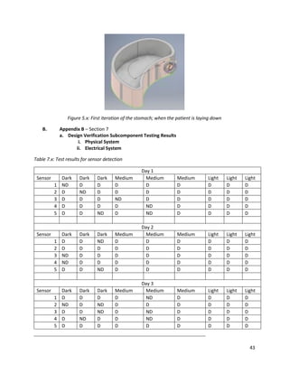
The document summarizes a nasogastric intubation training simulator project. It describes the clinical need for a more affordable and realistic simulator to train medical professionals on nasogastric intubation procedures. The document analyzes current simulator solutions and identifies gaps. It then outlines the design of a new Nasogastric Intubation Dummy simulator consisting of a physical model, fluid tubing system, and electrical components to provide feedback. Testing showed positive feedback from nurses but also areas for improvement, such as adding sphincter action.

![5
SECTION 2: PROBLEM STATEMENT AND CLINICAL NEED STATEMENT
2.1 Description of the team’s understanding of the problem
The current training simulators do not meet the needs of the nursing staff of the Purdue School of
nursing. A new training simulation must be developed that will meet those needs. There is room for
improvement in the cost and functionality category of the existing solutions in the market.
2.2 Problem Statement
Tube feeding is a very common procedure to administer basic nutrients and drugs into a person. In Britain,
there were 210 incidents reported related to nasogastric tube placement [1]. This method is mainly used
on babies and younger patients who have diseases like Down’s syndrome that can cause heart failure at
any moment and risk choking. During the procedure, the doctor will place a tube through the patient's
nose and into the stomach. A number of problems can occur during this procedure. These include:
placement of the tube into the patient's brain, damage to the lining of the esophagus causing infection,
and placement into the lungs causing sepsis. All of these are caused by improper technique and experience
with the procedure. One of the most imminent problems in medical and nursing school is how medical
simulators do not accurately mimic real life conditions. This problem includes the accurate modelling of
Nasogastric intubation for training purposes. Some problems with the existing models include not being
able to insert the tube further than 5 centimeters into the model due to existing mechanical parts. Other
problems include the incorrect sense of success for an accurately performed procedure. There is no way
to quantify the chance of success or failure to better train nurses and doctors.
2.3 Clinical Need Statement
There is a need for a way to provide a realistic simulation of nasogastric intubation to properly train
medical personnel for the real world. The simulation should monitor where the tube would go in an actual
human body. This would help improve the skill of the nurses by notifying them when they have incorrectly
placed the tube in the dummy. It should also produce obstructions. Not only will this more accurately
simulate real life procedures, it will also make the training more in-depth and challenging. and provide
real time feedback to the progress of intubation. Another key need is for the solution to be as anatomically
similar to its real life counterpart as possible. The nasal cavity as well as the trachea esophagus split are
important area for this. The nasal cavity has a certain unique geometry that can make it difficult to
perform the procedure. If the tube enters the trachea, then the patient will begin to cough. The procedure
will have to restarted and this wastes time and money. Making it more life-like also include items like the
ability to aspirate fluid. This means that, like in the actual procedure, fluid can be removed or replaced in
the simulation. The PH of the patients’ stomach contents can also be tested by fluid removal. This will add
to the overall realness of the solution thus providing a stronger learning tool for the user. In the future it
could be able to be incorporated into existing models or simulators, therefore providing a relatively cheap
and easy transition from the current simulator to the solution. Most importantly, it should be an effective
learning tool to better prepare nurses and doctors to preform nasogastric intubation.](https://image.slidesharecdn.com/5729e071-a112-414f-a6bf-66775d609275-170201144307/85/Senior-Capstone-Nasogastruc-Intubation-Training-5-320.jpg)
![6
SECTION 3: PROBLEM DESCRIPTION
3.1 Summary of Clinical Problem
Esophagus is a long tube connecting the throat to the stomach. It is roughly 8 cm long in a healthy adult
and lined with tissue called mucosa. The normal function of the esophagus is to take food and water from
the mouth and transport it to the stomach. It achieves this by muscles that constantly perform peristalsis
when stimulated. There are two different muscles groups in the esophagus; the upper esophageal and
the lower esophageal sphincter. The Upper Esophageal Sphincter (UES) contribute to the conscious
motion of breathing, eating, belching and vomiting. The Lower Esophageal Sphincter (LES) contribute to
preventing any stomach acid or food to re-enter the esophagus. Both of these need to work in
coordination with the other to function properly [2]. There are extenuating circumstances when overdose
of drug could cause severe fatalities and aspirating the stomach or administering activated charcoal is the
only methods to reduce the harmful effect of the drug on the body. All of these factors and more
contribute to the growing use of nasogastric tube to administer drugs and nutrients and aspirate stomach
content [3].
Patients in certain situations are also administered many different drugs and nutrients by using NG tubes.
Many patients who are in a coma or have esophagus cancer require NG tube to keep them functioning
well. Patients that are not able to use the esophagus to their bare minimum capacity start to become
under nourished and can cause many different complications with not being able to take in enough
vitamins and minerals necessary. Some patients in a comatose condition could be put at risk of more
severe complications if drugs and nutrients aren’t administered properly to them. Half a million
nasogastric tubes are misplaced every year, leading to death and can cost health care providers millions
of dollars [1]. These misplaced tubes are typically misguided into the lungs because of the closeness of
the esophagus and trachea entrances. The lack of proper training for nurses and healthcare professionals
is the main determinant of tis improper placement of nasogastric tubes. These complications from
misplacement can be severe ranging from simple coughs to drowning a patient. It’s difficult to monitor
this and can occur in any hospital that uses nasogastric tubes as a source of aspirating or administering
drugs to a patient. Between 2001 and 2011, there was more than $10 million paid to resolve lawsuits filed
for injuries and death due to NG tube placement in Chicago alone [1]. This high cost and risk can easily be
minimized if there was a better training simulation on the market. Asking the nurses at Purdue, it became
clear that they almost had no idea how to place an NG tube when they first had to on an actual patient;
attributing that to the lack of experience they had in the classroom. Testimony from nursing instructors
claimed that current training simulators cost too much for how little they actually teach the students.
3.2 Summary of Current Solution Landscape
There is a relatively crowded market with many different solutions that can assist in training healthcare
professionals on placing nasogastric tubes.
Table 3.1: Table of existing solutions
Product/Solution Ability to
aspirate/administer
drugs into stomach
Provides real time
feedback
Cost ($)
SimMan X X 1350](https://image.slidesharecdn.com/5729e071-a112-414f-a6bf-66775d609275-170201144307/85/Senior-Capstone-Nasogastruc-Intubation-Training-6-320.jpg)
![7
3-DMed ✔ ✔ 2380
Laerdal NG Tube and
Trach Care Trainer
✔ ✔ 1350
3B Scientific ✔ ✔ 1010
SimMan is a simulation model that uses a life size dummy to train nurses in many different medical
procedures. One of the procedures fitted into the SimMan is the ability to insert a nasogastric tube into
the dummy and practice this method. There are many drawbacks from using this solution to practice the
method. One of the most eminent drawback is that there is no sense of success provided by the dummy
if the tube has been placed accurately in the correct location. The other drawback of using this dummy is
that there is no way to administer or aspirate drugs to and from the dummy. The SimMan also cost roughly
$1,350 which is a very expensive solution to a very simple training procedure [4].
3-DMed nasogastric tube feeding simulator is another solution that can be used to treat caregivers in the
nasogastric tube feeding method. This solution is able to aspirate and administer drug into the dummy
and also provide a sense of success by having a semitransparent body. However, the main drawback of
using this dummy is the cost associated with it. The Nasogastric Tube Feeding simulator is $2,380. This is
the most expensive solution in the market compared to the SimMan [5].
Laerdal NG tube and Trach Care trainer is another solution that is very similar to the 3-DMed simulator.
They have the same qualities, however the Laerdal simulator is cheaper than the 3-DMed and can perform
the same functions [6].
The last and probably the best existing solution is the 3B Scientific. One very attractive feature of this
solution is that the manufacturers added replaceable parts that could be changed out if needed, or simply
added for a different function. Some of these additional replaceable items include lubricants and trachea
tube. This would provide the user with a longer lasting solution that works perfectly fine after some wear
and tear. However, the price of the product is still unattractive [7].
3.3 Assessment of Emerging Technology
One of the most recent technologies that has come into the market is the use of virtual reality for nurse
intubation training. This works by providing the nurses with a 3D model that accurately mimics the
conditions inside the nasal cavity and neck of a human being. Using this model, developers can extrapolate
the use of this device to train medical professionals. There is also an additional feature that provides the
user with a haptic feedback feeling, very similar to the one received when placing an NG tube. This could
make the model more realistic thus giving a better quality of training to healthcare professionals. There
are many peer review articles released about this technology, however no substantial progress has been
done to make this technology feasible in a clinical setting [8].](https://image.slidesharecdn.com/5729e071-a112-414f-a6bf-66775d609275-170201144307/85/Senior-Capstone-Nasogastruc-Intubation-Training-7-320.jpg)
![8
Figure 3.1: This figure shows the nasogastric system model of the virtual reality technology currently
under development [8].
3.4 Gap Analysis
Table 3.2: Existing and Emerging Solutions Gap Matrix
Existing and
Emerging Solution Brief Description Cost
Provides
Real Time
Feedback
Able to
Aspirate
Stomach
Contents
Realistic
Feedback
SimMan A simple dummy that is used for
many different training
simulations
-- +/- -- -
3D-Med A semi-transparent dummy for NG
tube placement specifically
--- ++ ++ -
Laerdal NG Tube and
Trach Care Trainer
A semi-transparent dummy for NG
tube placement specifically
-- ++ ++ -
3B Scientific Dummy torso with removable
parts that can be added or taken
out for different training functions
+/- ++ - -
Virtual Reality
Simulation
Virtual reality model of
nasogastric intubation instead of a
physical model
+/- ++ --- +
After assessing all of the existing and emerging solutions on the market a clear gap was seen. As shown
by the Pugh matrix, there is a gap for a solution with a low cost and but high efficacy for realistic training.
There is a need for a solution that can provide a combination of real time feedback, realistic feedback and](https://image.slidesharecdn.com/5729e071-a112-414f-a6bf-66775d609275-170201144307/85/Senior-Capstone-Nasogastruc-Intubation-Training-8-320.jpg)
![9
ability to aspirate the stomach while maintaining a low cost. All the existing solutions in the market have
some of the design specifications that were taken into consideration but more features would allow the
user to experience a more well-rounded training technique. Specifically, a lower cost and realistic
feedback seems to be the two largest needs in the gap.
3.5 Market Analysis
Market Size: With more than 18,705 total medical school graduates in 2015 [9] and 80,767 nursing
school students in the United States [10] the market for who will use our solution is considerably large.
There is also potential for growth in the market because the solution could expand from just being used
in classroom settings to also being used in hospitals for practice of nasogastric intubation.
Market Costs: Most medical schools will have at least one of the dummy models that were listed in the
current solution table; the cheapest being $1,350. Since most schools will have multiple models on hand
for training many people at one time, the cost could get pretty large. If a school had 10 models of $1,350,
the cost could end up reaching $13,500 all for ineffective training. As mentioned, a majority of that money
would go to waste because it would still not properly train the individuals; the costs go beyond just money
Solution Costs: Our target cost is about $150 because we plan to either use materials available to us or
materials that are relatively cheap. The main cost of this product will be the electrical parts since reliable
working electrical components are essential for the product to effectively work, thus meeting the design
requirements. With further iterations of the design and more research, there is a possibility to lower
that cost more while still maintaining its efficacy. Lastly, the design could eventually become one that
could be implemented into already existing dummies, lowering the cost and saving the schools even
more money.](https://image.slidesharecdn.com/5729e071-a112-414f-a6bf-66775d609275-170201144307/85/Senior-Capstone-Nasogastruc-Intubation-Training-9-320.jpg)
![10
SECTION 4: DESIGN SPECIFICATIONS
4.1 Target Customer and Rationale
The main target customers for NID, the new product, are aspiring medical professionals who would use
this device to further their training in the nasogastric intubation procedure. This device would be used in
hospitals and nursing schools after introduction in the market. The main factor when considering the
development of the product is the cost of the solution. Most of the training dummies are heavily
overpriced and a cheap but reliable solution would be the most efficacious way to introduce the product
into the market. To avoid improper training by developing an inaccurate anatomy of the nasogastric tube
and nasal cavity, the product would be approved by the Liaison Committee of Medical Education before
release into the market.
4.2 Summary Table of Design Specifications
Table 4.1: Summary of the design specifications
Design Needs Design Specification Originated from
Ethical
considerations or
Hazard analysis
Weight
Real Time Monitoring Requirement for an indicator to check the
location of the tube during procedure
Ethical 5
Simulate Obstructions Must be able to accurately mimic any
complication typically seen when placing an NG
tube
Ethical 3
Realistic Feedback Solution should make realistic audio sounds
(coughs and gurgles) that would typically be
heard at different points of a procedure
Ethical 4
Cost Less Than
Competitors
Cost less than $1,350 [11] Ethical 2
Able to Aspirate and
Administer Drugs
Solution must be able to draw fluid as well as
add drugs or fluid into the stomach
Ethical 3
Model is to Scale of
an Actual Adult
Human
Esophagus: 25 cm +/- 2 cm [12]
Nasal Cavity uses literature modeling
Hazard Analysis 4
Removable Parts Solution must have parts that can be removed
for cleaning
Ethical 2
The device should be able to provide the user with a real time monitoring system on where exactly the
tip of the nasogastric tube is during the whole procedure. Mains checkpoint areas should be the back of
the nasal cavity, neck, trachea entrance and stomach entrance. This would prove to be very helpful for
the user since the existing system has no way of monitoring the exact whereabouts of the feeding tube
inside the dummy. By. accurately monitoring the progress of the tube inside the dummy, the instructor
would be able to help the student adjust their technique.
Since the device is going to be used strictly for training purposes, to make it more realistic there would
need to be anomalies or obstructions that would mimic a real human esophagus tract. Hence, adding a](https://image.slidesharecdn.com/5729e071-a112-414f-a6bf-66775d609275-170201144307/85/Senior-Capstone-Nasogastruc-Intubation-Training-10-320.jpg)
![11
trachea passage would make the system more realistic and complex. Also proper resistance trains the
user how to maneuver the tube, similarly to what would be felt in a patient. To meet this, the product
should accommodate the actual dimensions of the human nasal cavity, entrance to trachea and
esophagus; the esophagus in an average adult human is 25cm long [13].
Current solutions do not have any method to provide the user with real time feedback. Some of the
realistic feedback would include coughing sounds when the tube enters the trachea and gurgling sounds
when the tube enters the stomach. These would better help the user understand the geometry of the
esophageal tract and to hone their skills in performing this procedure. Another very important feature
that the existing system lacks is the sense of success. The users do not have any way to tell if they have
performed the procedure correctly by inserting the tube in the stomach. Again this can be achieved using
the audio feedback. This real time feedback system would help the nurses know what mistakes they are
doing and improve upon them while training by accurately displaying if they have placed the tube in the
stomach or slipped into the trachea.
Existing devices that attempt to train nurses in nasogastric tube intubation sell for about $1350 [11]. The
price is a major drawback and ward off target customers from buying it when considering the ineffective
training they provide. NIDS must be cheaper than other products in the market to make it more attractive
to the target customers. This will also allow more hospitals and nursing schools to purchase the device
and provide efficient training for a routine procedure.](https://image.slidesharecdn.com/5729e071-a112-414f-a6bf-66775d609275-170201144307/85/Senior-Capstone-Nasogastruc-Intubation-Training-11-320.jpg)
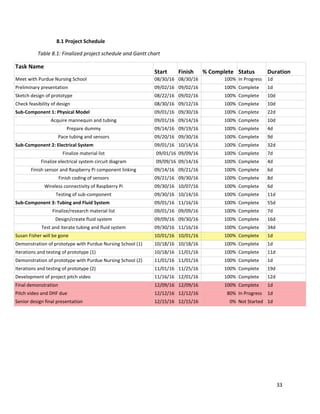
![14
Table 5.1: Subcomponent design table
Subcomponent Title Technical Description Contributing
discipline/skill
set
Design Specification
Addressed
Physical Model 25in x 18in [5] torso with a
plastic mannequin head
hollowed out and cut to scale.
Comes with abdominal opening.
machine skills,
mechanical
engineering.
removable parts, to
scale model
Electrical System Infrared sensors on the inside
of the modeled esophagus and
stomach that will indicate
where the tube is in the model,
Electrical
engineering
real time monitoring,
sense of success or
failure, realistic
feedback
Tubing and Fluid
System
A 25 cm esophagus with a 9-
liter removable stomach. A
short trachea tube will also be
included with the system to
detect if gastric fluids have
entered the respiratory tract at
all.
Fluid dynamics,
mechanical
engineering
to scale model,
removable parts, able
to aspirate and
administer drugs
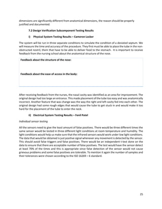
i) Physical Model – Cameron Locker
This subsection is going to focus on the body of the dummy, the head, and any moving parts within the
dummy. The dimensions of the body are based on average human schematics [5] as well as the head
using skin like plastic. The head will be hollowed out to provide realistic feel as the tube is inserted.
There will be an abdominal door that allows access to the parts of the model. This will allow the user to
replace or wash the stomach.
Figure 5.5. This will the nasal cavity model that would be used to accurately 3D print the nasal cavity and
remodel a deviated septum.](https://image.slidesharecdn.com/5729e071-a112-414f-a6bf-66775d609275-170201144307/85/Senior-Capstone-Nasogastruc-Intubation-Training-14-320.jpg)
![15
Figure 5.6. This would be the make do mannequin that would be used for all purposes of training.
ii) Electrical System – Fenil Patel
Method 1 – Passive Infrared sensors [September 30, 2016]
This subsection deal with everything electrical in the projects. There are going to be passive infra-red
sensors placed along the lines of the esophagus to detect if there is any motion in the tube and give
feedback to the user to determine the accurate position of the tube at that point of time. There is going
to be an analog front end to the system that would amplify signals obtained from the sensor and convert
them into digital signals that would be sent to a mini processor to decode.
Another important part of this subsection is the configuration of the mini processor with a wireless
adapter to transmit signals wirelessly to a mobile device. -The mobile device would be the front end of
the device and all the electronics would be controlled from here.](https://image.slidesharecdn.com/5729e071-a112-414f-a6bf-66775d609275-170201144307/85/Senior-Capstone-Nasogastruc-Intubation-Training-15-320.jpg)
![16
Figure 5.7: This figure shows the arrangement of PIR sensors with the attachment to the micro controller.
The second part of the electrical system is the python code that would be used to control the sensors
and detect every signal within the dummy.
Iteration 1 – using a 'yes' or 'no' signal output [October 7. 2016]
The first code written is provided in detail in the appendix of the document for section 5 electrical
subsystem. In brief this code detected a signal for every trigger giving a signal greater than 0 for every
detection and 0 in its default state. This was a digital method used to track changes in the conductance of
the sensors. However, the first iteration had a lot of false positive and this was changed in the following
iterations.
Iteration 2 – Peak finder function integrated with a 'yes' or 'no' function [November
18, 2016]
This iteration proved to be the most efficient in reducing the number of false positives. This was achieved
by using the peak finder function and not permitting sensors further in the esophagus to be triggered
before the ones above. Another important change made to the sensors was to set their initial state to
false, hence calibrating sensors to a non-trigger state. Previous iterations did not attempt to reset the
sensors after every trial, however this was adjusted in the following iteration. The detailed code can be
found in section 5 of the appendix, labelled under electrical subsystems. Some internal features were also
added such as addition of sound in the dummy for both the trachea and the stomach sensors.
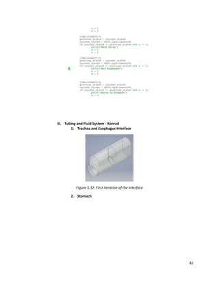
iii) Tubing and Fluid System – Konrad Wolfmeyer
This subcomponent includes the tubes inside the dummy that will be used for the esophagus, the
removable stomach and the respiratory aspiration training. Adult esophagus’ are about 25 cm in length
so the tube will have to meet that desired length; the esophagus also has an inner diameter of 2 cm [14].](https://image.slidesharecdn.com/5729e071-a112-414f-a6bf-66775d609275-170201144307/85/Senior-Capstone-Nasogastruc-Intubation-Training-16-320.jpg)
![17
The trachea’s length will not be anatomically accurate because all that is needed is enough room to tell
the user if the tube went into the trachea versus the esophagus. This can be done with a length of a few
inches. Unlike the esophagus, the trachea has a slightly larger inner diameter, 2.5 cm, so that will have to
be taken into consideration [14]. The capacity of the stomach can expand to .9 liters so it was determined
that the removable stomach should also be that size [15]. However, if the size of the stomach seems to
be too large, it may be decreased. It will also have to be water resistant or waterproof since it will be
holding liquid when aspiration training is done. Lastly, sensor boxes will be placed along the system to
hold the sensors that will be monitoring the NG tube progress.
The following physical models below would be used for various different functions in the dummy. Some
of these functions include placing the sensors, separating different parts of the neck and having a
stomach pouch.
The following sketch was drawn to design an anatomically correct model of the nasogastric system. This
sketch was then used for Autodesk Inventor modeling and eventually the different parts were 3D
printed.
Figure 5.8: Full system sketch of the tubing and fluid system subcomponent](https://image.slidesharecdn.com/5729e071-a112-414f-a6bf-66775d609275-170201144307/85/Senior-Capstone-Nasogastruc-Intubation-Training-17-320.jpg)
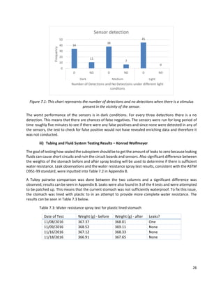
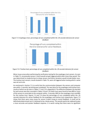
![23
SECTION 7: VERIFICATION AND VALIDATION OF DESIGN
7.1 Design Verification Plans for Subcomponents
i) Physical Model Testing Plans – Cameron Locker
To verify the size of the body, all other subcomponents must fit within. After testing other
subcomponents, the body will be opened and subcomponents like the stomach will be removed for
cleaning. The nose and head will be tested by inserting a standard nasogastric tube through each nostril.
This will test the geometry of the nose. The head will be a hard acrylic plastic. The nose of the head will
be removed and replaced with a 3D printed nose according to the standard geometry paper [16]. The
mannequin head acquired is hallow and the base has been expanded to fit the size of the human hand.
As our device does not directly interact with the user, and is only meant for training doctors and nurses,
there are no federal regulations pertaining to the use of this device.
ii) Electrical System Testing Plans – Fenil Patel
Two different tests will be performed to assess the overall function of the system.
Testing protocol 1 – Individual sensor testing
1. Attach individual sensors to the electronic component, specifically the microprocessor GPIO Port
2 [Pin 3].
2. Attach Sensor power to Pin 2 and GND to Pin 6
3. Boot up microprocessor and run file sensortest.py. This file would enable the GPIO port on the
microprocessor to obtain signals from the sensor. Hence, the GPIO ports would be able to display
when the senor is triggered and when it isn't triggered.
4. Place obstructions before the sensor and detect if there is a message displayed on the screen.
"Motion detected" would be displayed if there is an object in front of the sensor and "No motion
detected" would be displayed when there are no obstructions in front of the sensor.
5. The number of false positives would be recorded in order to make sure that the sensor is being
triggered only when there is a stimulus and all the false triggers are mitigated.
Testing protocol 2 - Sensors testing and assembly
1. Attach the circuit shown in the diagram below.](https://image.slidesharecdn.com/5729e071-a112-414f-a6bf-66775d609275-170201144307/85/Senior-Capstone-Nasogastruc-Intubation-Training-23-320.jpg)
![24
2. Once the circuit is attached, boot up the raspberry pi and run fullsystemtest.py. This script would
calibrate all the GPIO ports and sensors in order to obtain signals as a whole system.
3. After this is running, place all the sensors in one line and then pass an obstruction such as a tube
horizontally in front of the sensors. This would be able to stimulate a trigger for the sensors.
4. The software should be able to accurately tell you the sensors that have been triggered and those
that haven't by displaying an interactive chart and marking the ones that have triggered after the
obstructions.
5. Record the number of false positives and false negative to improve python code for the sensor
and change the sensitivity and delay for each of the sensors.
The first test that is performed is used to make sure that there are no faulty sensors in the pair
that might give the user false readings and the second test that is performed is used to calibrate
the system and test if the whole system functions together and can detect the motion of the tube.
It is worth noting that all the samples and their tolerance for the severity of their failure were
chosen using the ISO 19269-6 standard. This was then tested and the results for the sensor
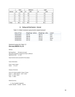
triggers were processed with different statistical tests.
iii) Tubing and Fluid Testing Plans – Konrad Wolfmeyer
These verification procedures are performed to demonstrate that the tubing/fluid system can be used to
properly model the pathway of an NG tube during a nasogastric intubation procedure.
With the possibility of fluid being added and taken out of the stomach, it is necessary that the tubing
system is properly sealed to protect the electronics that are located outside of the tubes. The stomach
will be the priority for this testing protocol since it will house liquid for aspiration purposes. Testing for
water resistance will be similar to that of the ASTM D951-99 standard test method for water resistance
[17]. Each part being tested for water resistance will be weighed prior to testing. Then they will be placed
on a surface and sprayed continuously for 10 seconds. Immediately after, any liquid on the surface will be
removed with paper towel. Lastly the part will be weighed and an examination of the part will be made
to find any leakages. This test will be done multiple times and a Tukey test, with a 95% confidence level,
will be used to determine if there is any significant difference between the weights before and after the
spray test. If significant difference determined or leaks are observed, the design will have to be adjusted
to fix the issue
Since the sensors will be placed along the esophagus model for real time feedback to the user, there is a
possibility for obstructing the placement of the NG tube. These possible obstructions would not be found
in an actual esophagus which is why they should be minimized as much as possible. A simple way to test
the occurrence of obstructions would be to insert the NG tube into the nasal cavity and run it into the
stomach. Once any obstruction due to the sensors is felt, it should be documented. The target occurrence
rate of an obstruction being felt should be less than 10% of the time the procedure is done. If the
occurrence rate is higher than the target rate, the reasons should be identified and adjusted. The testing
procedure should be continually repeated until the occurrence rate is less than the target.
Lastly, the model should be as anatomically realistic as possible to give the medical professionals the
best training possible. Any dimensions of the parts should be close to anatomical dimensions. If the](https://image.slidesharecdn.com/5729e071-a112-414f-a6bf-66775d609275-170201144307/85/Senior-Capstone-Nasogastruc-Intubation-Training-24-320.jpg)


![37
REFERENCES
[1] "Misplaced NG tubes a major patient safety risk", Ahcmedia.com, 2016. [Online]. Available:
http://www.ahcmedia.com/articles/135136-misplaced-ng-tubes-a-major-patient-safety-risk. [Accessed:
28- Aug- 2016]. [3] 2016. [Online]. Available:
https://www.aamc.org/download/321532/data/factstableb2-2.pdf. [Accessed: 13- Sep- 2016].
[2] "The Esophagus (Human Anatomy): Picture, Function, Conditions, and More", WebMD, 2016.
[Online]. Available: http://www.webmd.com/digestive-disorders/picture-of-the-esophagus. [Accessed:
13- Sep- 2016].
[3] "Nasogastric Intubation and Feeding", Healthline, 2016. [Online]. Available:
http://www.healthline.com/health/nasogastric-intubation-and-feeding#Purpose2. [Accessed: 13- Sep-
2016].
[4] "SimMan®", Laerdal.com, 2016. [Online]. Available: http://www.laerdal.com/us/doc/86/SimMan.
[Accessed: 13- Sep- 2016].
[5] "Nasogastric Tube Feeding Simulator", 3-Dmed, 2015. [Online]. Available: https://www.3-
dmed.com/product/nasogastric-tube-feeding-simulator. [Accessed: 13- Sep- 2016].
[6] "NG Tube and Trach Care Trainer", Laerdal.com, 2016. [Online]. Available:
http://www.laerdal.com/us/doc/96/NG-Tube-and-Trach-Care-Trainer. [Accessed: 13- Sep- 2016].
[7] "Life/form® NG Tube & Trach Skills Simulator - LF01174U - Advanced Trauma Life Support (ATLS) - 3B
Scientific", A3bs.com, 2016. [Online]. Available: https://www.a3bs.com/lifeform-ng-tube-trach-skills-
simulator-w99834-lf01174u,p_1455_14397.html. [Accessed: 13- Sep- 2016]. [6X]"Nasogastric Tube
Feeding Simulator", 3-Dmed, 2015. [Online]. Available: https://www.3-dmed.com/product/nasogastric-
tube-feeding-simulator. [Accessed: 13- Sep- 2016].
[8] K. Choi, X. He, V. Chiang and Z. Deng, "A virtual reality based simulator for learning nasogastric tube
placement", Computers in Biology and Medicine, vol. 57, pp. 103-115, 2015.
[9] 2016. [Online]. Available: https://www.aamc.org/download/321532/data/factstableb2-2.pdf.
[Accessed: 13- Sep- 2016].
[10] "American Association of Colleges of Nursing | New AACN Data Show an Enrollment Surge in
Baccalaureate and Graduate Programs Amid Calls for More Highly Educated Nurses",Aacn.nche.edu,
2016. [Online]. Available: http://www.aacn.nche.edu/news/articles/2012/enrollment-data. [Accessed:
13- Sep- 2016].
[11] 2009. [Online]. Available: http://www.laerdal.com/binaries/ADBXVAWQ.pdf. [Accessed: 01- Sep-
2016].
[12] Z. Awad, "Correlations between esophageal diseases and monomeric length: a study of 617
patients”, Journal of Gastrointestinal Surgery, vol. 3, no. 5, pp. 483-488, 1999.](https://image.slidesharecdn.com/5729e071-a112-414f-a6bf-66775d609275-170201144307/85/Senior-Capstone-Nasogastruc-Intubation-Training-37-320.jpg)
![38
[13] Shamiyeh, A., Szabo, K., Granderath, F., Syré, G., Wayand, W., & Zehetner, J. (2009). The esophageal
hiatus: what is the normal size? Surgical Endoscopy, 24(5), 988-991. http://dx.doi.org/10.1007/s00464-
009-0711-0
[14] "Esophagus Anatomy: Gross Anatomy, Microscopic Anatomy, Pathophysiologic Variants",
Emedicine.medscape.com, 2016. [Online]. Available: http://emedicine.medscape.com/article/1948973-
overview. [Accessed: 13- Sep- 2016].
[15] Radcliffe, Donald V. Stomach. Compton’s Encyclopedia Online v3.0. The Learning Company, 1998.
[16] Y. Liu, M. Johnson, E. Matida, S. Kherani and J. Marsan, "Creation of a standardized geometry of the
human nasal cavity", Journal of Applied Physiology, vol. 106, no. 3, pp. 784-795, 2009.
[17] Standard Test Method for Water Resistance of Shipping Containers by Spray Method, ASTM D951 –
99, 2010](https://image.slidesharecdn.com/5729e071-a112-414f-a6bf-66775d609275-170201144307/85/Senior-Capstone-Nasogastruc-Intubation-Training-38-320.jpg)