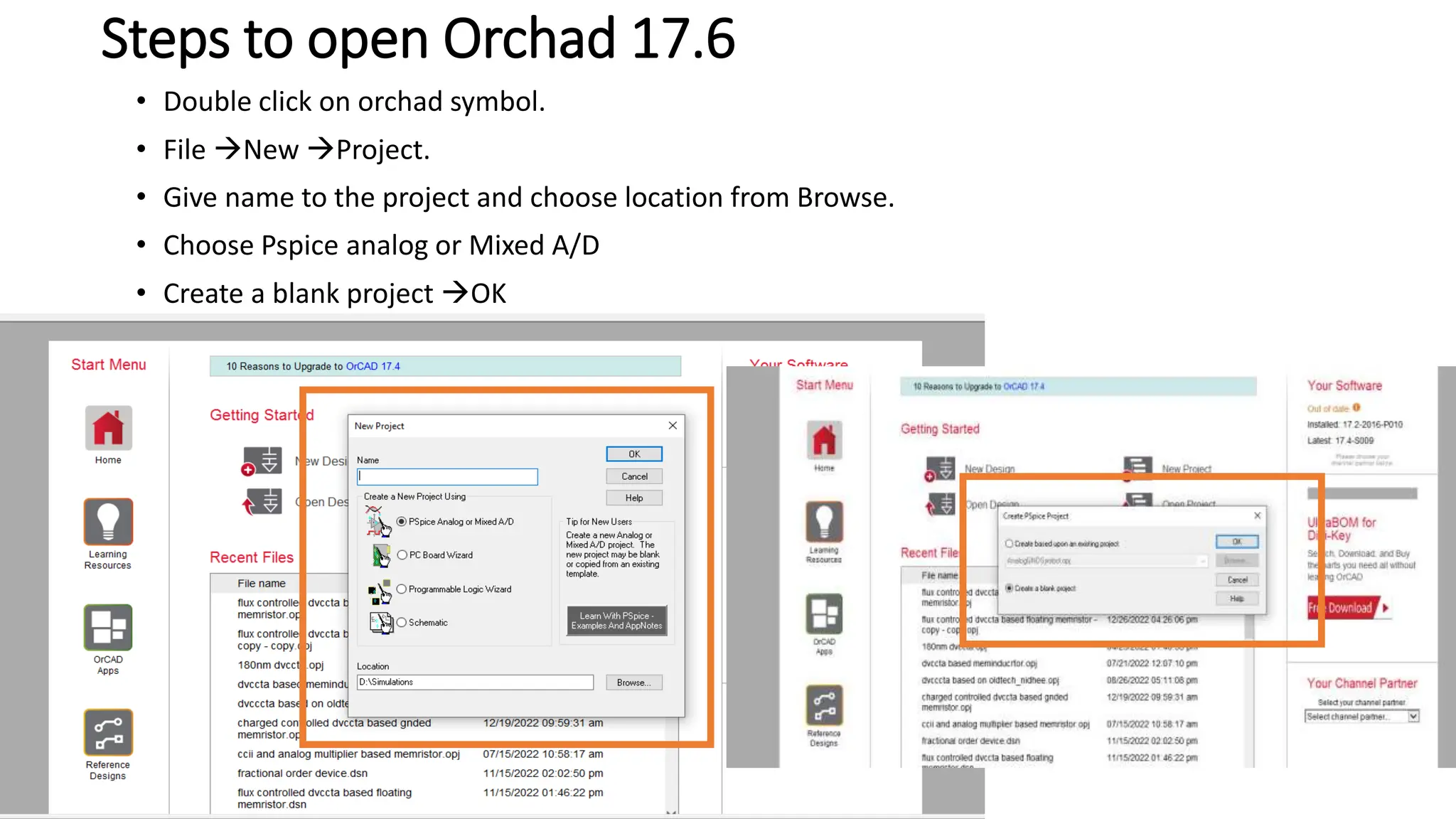
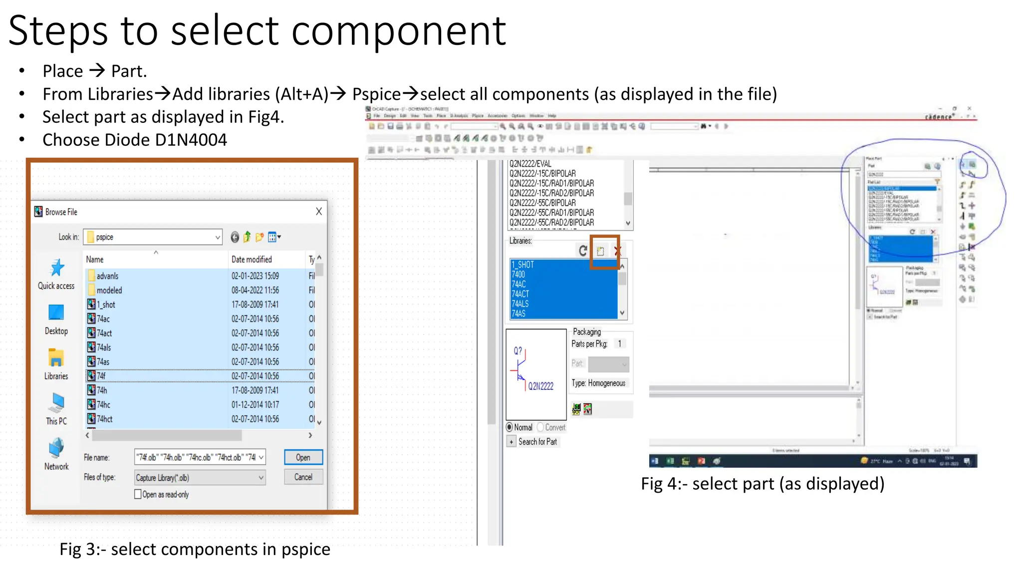
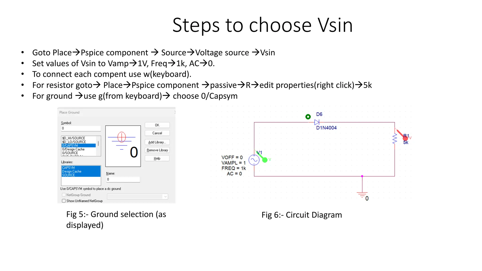
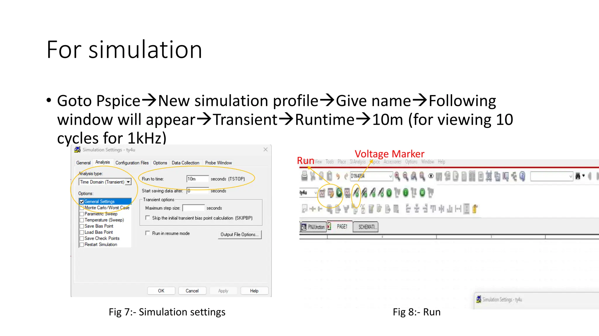
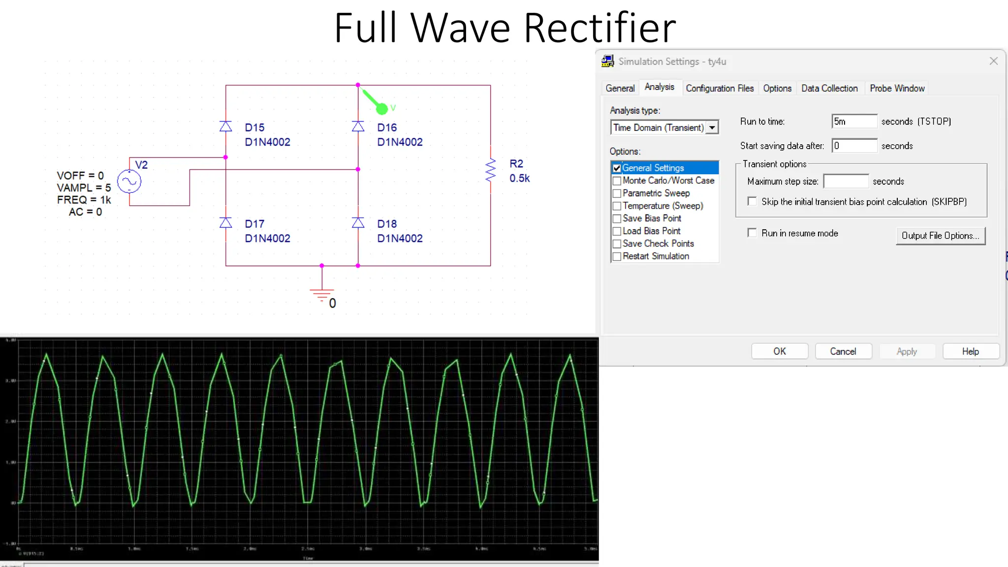
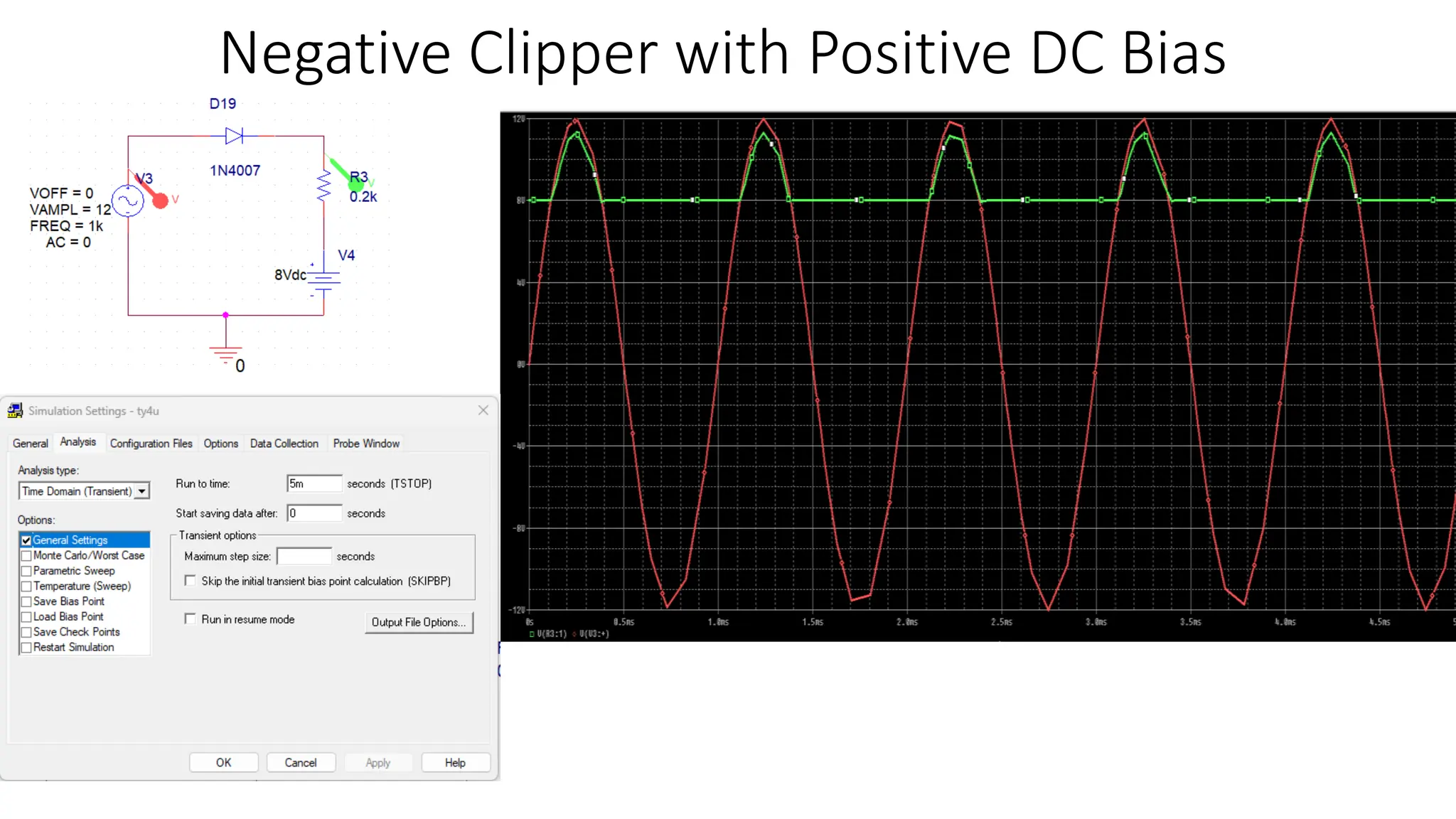
PSPICE
Contents
• Half Wave Rectifier
• Full Wave Rectifier
• Negative Clipper with Positive DC Bias
• Negative Clipper with Negative DC Bias
• Positive Clipper with positive DC Bias
• Positive Clipper with Negative DC Bias
• Positive clamper with positive Bias
• Positive clamper with Negative Bias
• Negative Clamper with Negative DC Bias
• Negative Clamper with Positive DC Bias
Steps to open Orchad 17.6
• Double click on orchad symbol.
• File New Project.
• Give name to the project and choose location from Browse.
• Choose Pspice analog or Mixed A/D
• Create a blank project OK
Steps to select component
• Place  Part.
• From LibrariesAdd libraries (Alt+A) Pspiceselect all components (as displayed in the file)
• Select part as displayed in Fig4.
• Choose Diode D1N4004
Fig 3:- select components in pspice
Fig 4:- select part (as displayed)
Steps to choose Vsin
• Goto PlacePspice component  SourceVoltage source Vsin
• Set values of Vsin to Vamp1V, Freq1k, AC0.
• To connect each compent use w(keyboard).
• For resistor goto PlacePspice component passiveRedit properties(right click)5k
• For ground use g(from keyboard) choose 0/Capsym
Fig 5:- Ground selection (as
displayed)
Fig 6:- Circuit Diagram
For simulation
• Goto PspiceNew simulation profileGive nameFollowing
window will appearTransientRuntime10m (for viewing 10
cycles for 1kHz)
Fig 7:- Simulation settings Fig 8:- Run
Run
Voltage Marker
Output
Full Wave Rectifier
Negative Clipper with Positive DC Bias
Negative Clipper with Negative DC Bias
Positive Clipper with positive DC Bias
Positive Clipper with Negative DC Bias
Positive clamper with positive Bias
Positive clamper with negative Bias
Negative Clamper with Negative Bias
Negative Clamper with positive Bias

PSPICE Diode applications.pptx

  • 1.
  • 2.
    Contents • Half WaveRectifier • Full Wave Rectifier • Negative Clipper with Positive DC Bias • Negative Clipper with Negative DC Bias • Positive Clipper with positive DC Bias • Positive Clipper with Negative DC Bias • Positive clamper with positive Bias • Positive clamper with Negative Bias • Negative Clamper with Negative DC Bias • Negative Clamper with Positive DC Bias
  • 3.
    Steps to openOrchad 17.6 • Double click on orchad symbol. • File New Project. • Give name to the project and choose location from Browse. • Choose Pspice analog or Mixed A/D • Create a blank project OK
  • 4.
    Steps to selectcomponent • Place  Part. • From LibrariesAdd libraries (Alt+A) Pspiceselect all components (as displayed in the file) • Select part as displayed in Fig4. • Choose Diode D1N4004 Fig 3:- select components in pspice Fig 4:- select part (as displayed)
  • 5.
    Steps to chooseVsin • Goto PlacePspice component  SourceVoltage source Vsin • Set values of Vsin to Vamp1V, Freq1k, AC0. • To connect each compent use w(keyboard). • For resistor goto PlacePspice component passiveRedit properties(right click)5k • For ground use g(from keyboard) choose 0/Capsym Fig 5:- Ground selection (as displayed) Fig 6:- Circuit Diagram
  • 6.
    For simulation • GotoPspiceNew simulation profileGive nameFollowing window will appearTransientRuntime10m (for viewing 10 cycles for 1kHz) Fig 7:- Simulation settings Fig 8:- Run Run Voltage Marker
  • 7.
  • 8.
  • 9.
    Negative Clipper withPositive DC Bias
  • 10.
    Negative Clipper withNegative DC Bias
  • 11.
    Positive Clipper withpositive DC Bias
  • 12.
    Positive Clipper withNegative DC Bias
  • 13.
    Positive clamper withpositive Bias
  • 14.
    Positive clamper withnegative Bias
  • 15.
    Negative Clamper withNegative Bias
  • 16.
    Negative Clamper withpositive Bias