Contents
19/06.2022
1. Contribution during2019-2022
2. Development of Nyquist Stability Criterion:
A. Principle of argument of complex variable
B. Checking stability with an example
C. Statement of Nyquist stability criterion (NSC)
D. Examples
E. Tutorial questions
3.
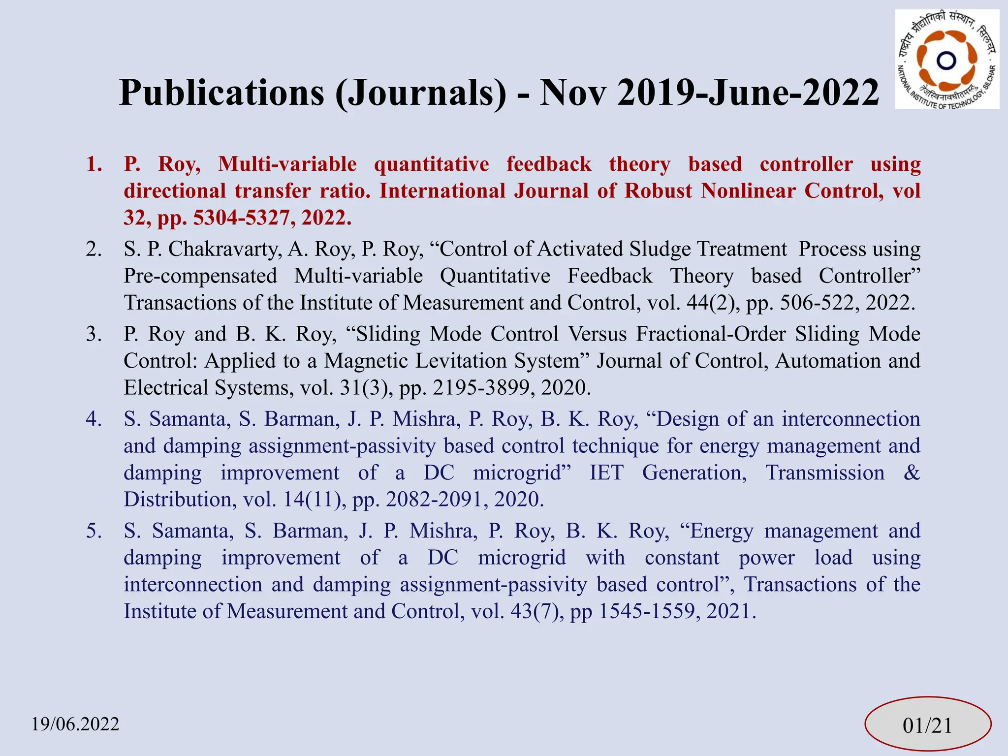
1. P. Roy,Multi-variable quantitative feedback theory based controller using
directional transfer ratio. International Journal of Robust Nonlinear Control, vol
32, pp. 5304-5327, 2022.
2. S. P. Chakravarty, A. Roy, P. Roy, “Control of Activated Sludge Treatment Process using
Pre-compensated Multi-variable Quantitative Feedback Theory based Controller”
Transactions of the Institute of Measurement and Control, vol. 44(2), pp. 506-522, 2022.
3. P. Roy and B. K. Roy, “Sliding Mode Control Versus Fractional-Order Sliding Mode
Control: Applied to a Magnetic Levitation System” Journal of Control, Automation and
Electrical Systems, vol. 31(3), pp. 2195-3899, 2020.
4. S. Samanta, S. Barman, J. P. Mishra, P. Roy, B. K. Roy, “Design of an interconnection
and damping assignment-passivity based control technique for energy management and
damping improvement of a DC microgrid” IET Generation, Transmission &
Distribution, vol. 14(11), pp. 2082-2091, 2020.
5. S. Samanta, S. Barman, J. P. Mishra, P. Roy, B. K. Roy, “Energy management and
damping improvement of a DC microgrid with constant power load using
interconnection and damping assignment-passivity based control”, Transactions of the
Institute of Measurement and Control, vol. 43(7), pp 1545-1559, 2021.
01/21
19/06.2022
Publications (Journals) - Nov 2019-June-2022
4.
Jounal Papers ConferencePapers Book Chapters
0
2
4
6
8
10
12
14
16
18
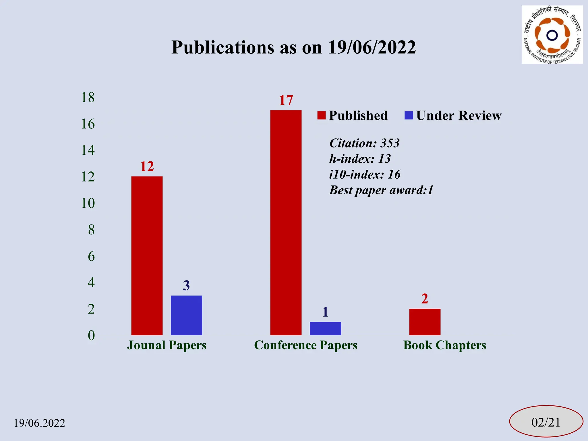
12
17
2
3
1
Published Under Review
Publications as on 19/06/2022
19/06.2022 02/21
Citation: 353
h-index: 13
i10-index: 16
Best paper award:1
5.
Teaching and Guidance(2019-2022)
• UG Teaching:
– Control systems, Signals and systems, Nonlinear Control systems, and
Digital Control Systems
• PG Teaching:
– Industrial automation, Multi-variable control, Nonlinear control,
Control System Design, Control System Laboratory
• PhD Guidance: 3 Ongoing
• PG Guidance: 6 M. Tech - Outcome: - 5 Conference papers
• UG Guidance: 4 Groups - Outcome: Participation in UGRC
03/21
19/06.2022
6.
Research Project
04/21
19/06.2022
• Too-Fun-Labs:- Design and Prototype Building of STEM Toys for
School Children
– Funded by Ministry of Micro, Small and Medium Enterprises, a
branch Government of India.
– Value: 5.77 Lakh
– Duration: 1 year
– Role: Co-PI
7.
Other responsibilities andActivities
• Departmental T&P Faculty Coordinator 2021 –Till Date
• Active Organizing Member for ACODS 2022
• Departmental Annual Report Coordinator -2020
• Faculty Advisor Gymkhana Music Club 2018-2020
• DUPC (EED) Secretary 2018-2020
• Faculty Advisor Electra Society 2017-Till Date
• Laboratory in Charge – Process Control Laboratory 2014-Till Date
• Organized STTP: Fractional-Order System and Control (2019)
• Reviewers: ISA Transactions, TIMC, IEEE Tr on CST and so on
05/21
19/06.2022
Outcome of thispresentation:
19/06.2022 07/21
At the end of this presentation, the students are expected to
be able to
1. Explain the Nyquist stability criterion (NSC) using principle of
argument of complex variable.
2. Apply NSC to determine the stability of the closed loop (C/L)
system for a given open loop (O/L) information.
10.
Principle of argumentof complex variable [1]
19/06.2022 08/21
Fig. 1: Mapping of a contour from s-plane to F(s)-plane.
s
r
1
1
( )
( ) ( )
r s z F s
s z F s
Fig. 1: Mapping of a contour from s-plane to F(s)-plane.
( )
F s
( )
F s
[1] Norman S. Nise, “Control Systems Engineering”, 6th edition Chapter 11, John Wiley & Sons, Inc., Singapore, 2011.
1
1
1
( )
( ) ( )
r s p
F s
s p F s
( )
w F s
s
r
( )
w F s
( )
F s
( )
F s
11.
Principle of argumentof complex variable [1]
19/06.2022 08/21
Fig. 1: Mapping of a contour from s-plane to F(s)-plane.
s
r
1
1
( )
( ) ( )
r s z F s
s z F s
Fig. 1: Mapping of a contour from s-plane to F(s)-plane.
( )
F s
( )
F s
[1] Norman S. Nise, “Control Systems Engineering”, 6th edition Chapter 11, John Wiley & Sons, Inc., Singapore, 2011.
1
1
1
( )
( ) ( )
r s p
F s
s p F s
( )
w F s
s
r
( )
w F s
( )
F s
( )
F s
12.
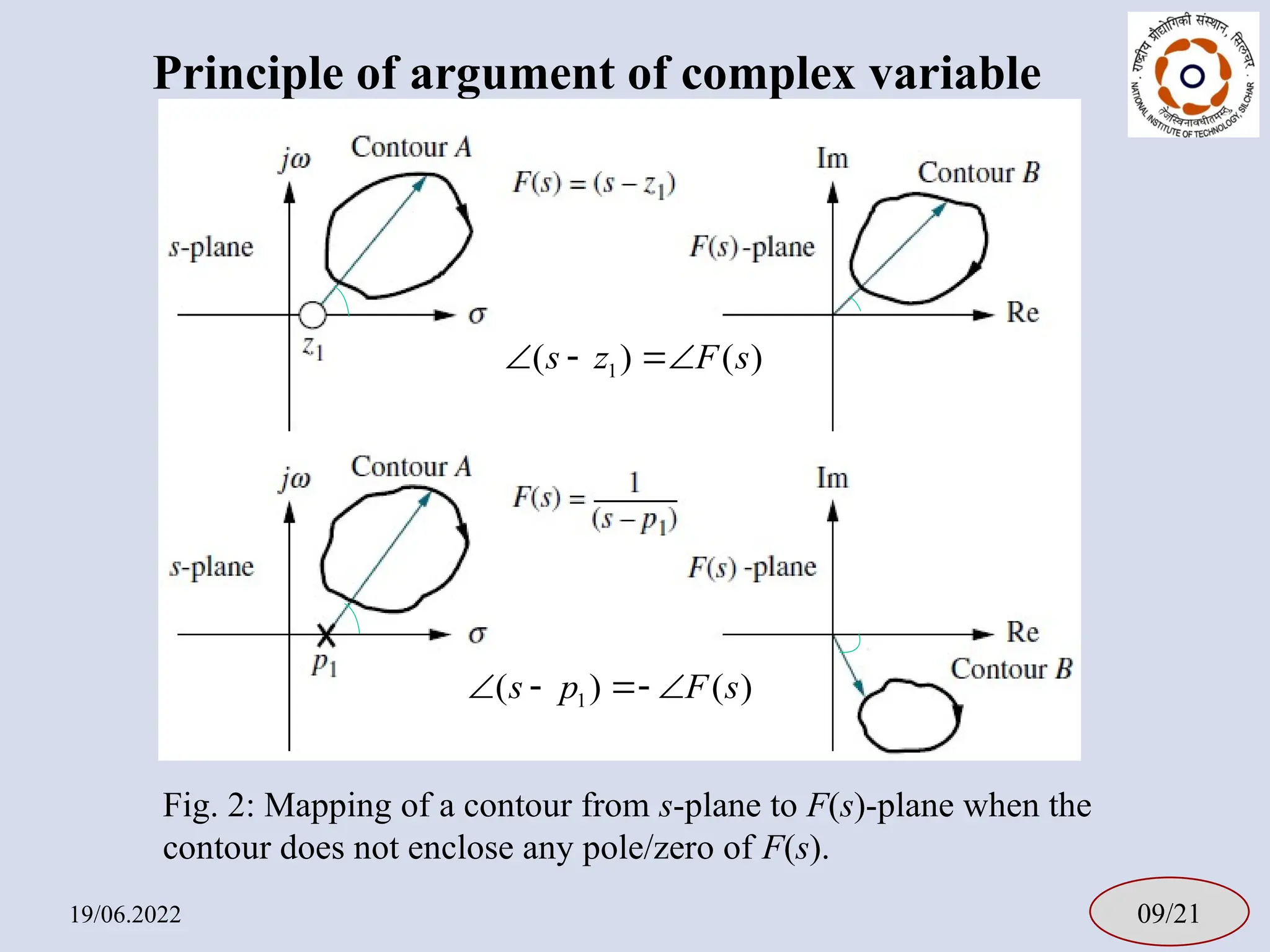
Principle of argumentof complex variable
19/06.2022 09/21
Fig. 2: Mapping of a contour from s-plane to F(s)-plane when the
contour does not enclose any pole/zero of F(s).
1
( ) ( )
s z F s
1
( ) ( )
s p F s
13.
Principle of argumentof complex variable
19/06.2022 10/21
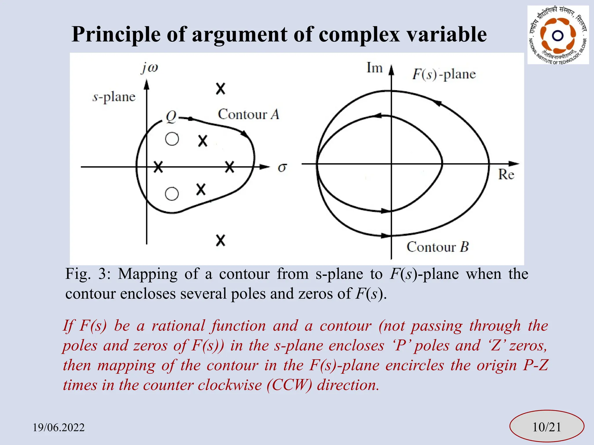
If F(s) be a rational function and a contour (not passing through the
poles and zeros of F(s)) in the s-plane encloses ‘P’ poles and ‘Z’ zeros,
then mapping of the contour in the F(s)-plane encircles the origin P-Z
times in the counter clockwise (CCW) direction.
Fig. 3: Mapping of a contour from s-plane to F(s)-plane when the
contour encloses several poles and zeros of F(s).
14.
Terminologies in basicfeedback system
19/06.2022 11/21
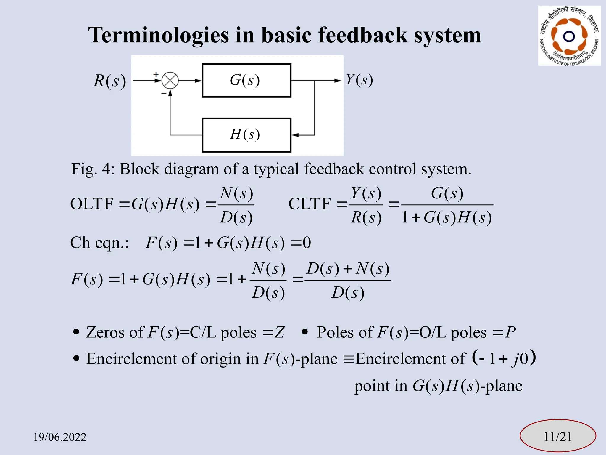
( ) ( ) ( )
OLTF ( ) ( ) CLTF
( ) ( ) 1 ( ) ( )
Ch eqn.: ( ) 1 ( ) ( ) 0
( ) ( ) ( )
( ) 1 ( ) ( ) 1
( ) ( )
N s Y s G s
G s H s
D s R s G s H s
F s G s H s
N s D s N s
F s G s H s
D s D s
( )
G s
( )
H s
( )
R s ( )
Y s
Fig. 4: Block diagram of a typical feedback control system.
Zeros of ( )=C/L poles Poles of ( )=O/L poles
Encirclement of origin in ( )-plane Encirclement of 1 0
point in ( ) ( )-pl
F s Z F s P
F s j
G s H s
ane
15.
How to determineC/L stability? [1]
19/06.2022 12/21
1
2
3
: , :0
: lim e ,
: 0
2 2
: , : 0
j
R
C s j
C s R
C s j
1
C
2
C
3
C
Fig. 5: Nyquist contour.
[1] Norman S. Nise, “Control Systems Engineering”, 6th edition Chapter 11, John Wiley & Sons, Inc., Singapore, 2011.
1. Select Nyquist contour in the s-plane.
2. Map the contour in the G(s)H(s)-
plane.
3. Find the number of CCW
encirclement (N) of (-1+j0) point in
the G(s)H(s)-plane i.e. (0+j0) point in
the F(s)=1+G(s)H(s)-plane.
4. N=P-Z
5. For C/L stability, Z=0, i.e. N=P.
16.
Example-I [2]
19/06.2022 13/21
1
OLTF:( ) ( )
( 1)( 2)
G s H s
s s
Fig. 6: Nyquist contour.
1
C 2
C
3
C
[2] Katsuhiko Ogata, “Modern Control Engineering”, 4th edition, Chapter 8, Pearson Education International, New Jersy, USA, 2002.
1 1
2 2
1
tan tan
2
1 4
1
For C : ( ) ( )
1
( 1)( 2)
G j H j
j j
s j
lim ej
R
s R
s j
17.
Example-I [2]
19/06.2022 13/21
Fig.6: Nyquist contour.
1
C 2
C
3
C
[2] Katsuhiko Ogata, “Modern Control Engineering”, 4th edition, Chapter 8, Pearson Education International, New Jersy, USA, 2002.
'
1
C
s j
lim ej
R
s R
s j
1
OLTF: ( ) ( )
( 1)( 2)
G s H s
s s
18.
Example-I [2]
19/06.2022 13/21
1
OLTF:( ) ( )
( 1)( 2)
G s H s
s s
Fig. 6: Nyquist contour.
1
C 2
C
3
C
[2] Katsuhiko Ogata, “Modern Control Engineering”, 4th edition, Chapter 8, Pearson Education International, New Jersy, USA, 2002.
2
2 2
1 1
For : ( ) ( ) lim lim
(Re 1)(Re 2)
j
j j
R R
C G s H s e
R
'
1
C
'
2
C
3 1
3
Maping of is the mirror image of the maping of
about real axis.
For : C C
C
s j
lim ej
R
s R
s j
19.
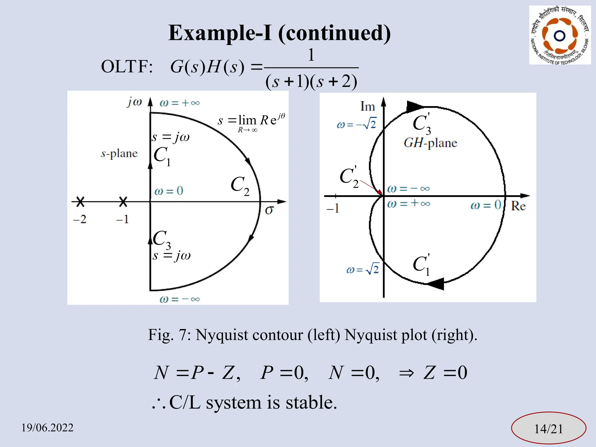
Example-I (continued)
19/06.2022 14/21
,0, 0, 0
C/L system is stable.
N P Z P N Z
Fig. 7: Nyquist contour (left) Nyquist plot (right).
1
C
2
C
3
C
'
1
C
'
2
C
'
3
C
1
OLTF: ( ) ( )
( 1)( 2)
G s H s
s s
s j
lim ej
R
s R
s j
20.
Formal statement ofNyquist stability criterion
19/06.2022 15/21
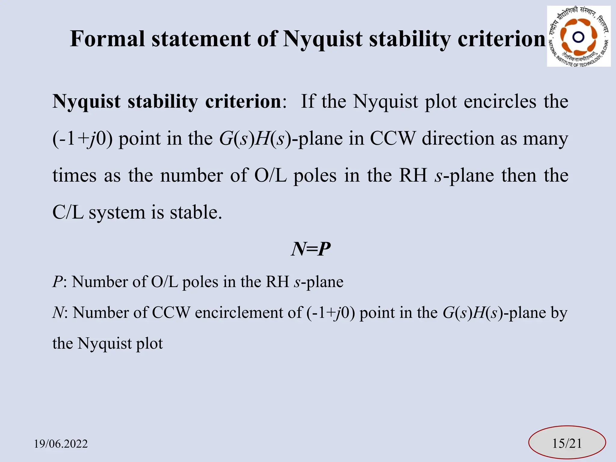
Nyquist stability criterion: If the Nyquist plot encircles the
(-1+j0) point in the G(s)H(s)-plane in CCW direction as many
times as the number of O/L poles in the RH s-plane then the
C/L system is stable.
N=P
P: Number of O/L poles in the RH s-plane
N: Number of CCW encirclement of (-1+j0) point in the G(s)H(s)-plane by
the Nyquist plot
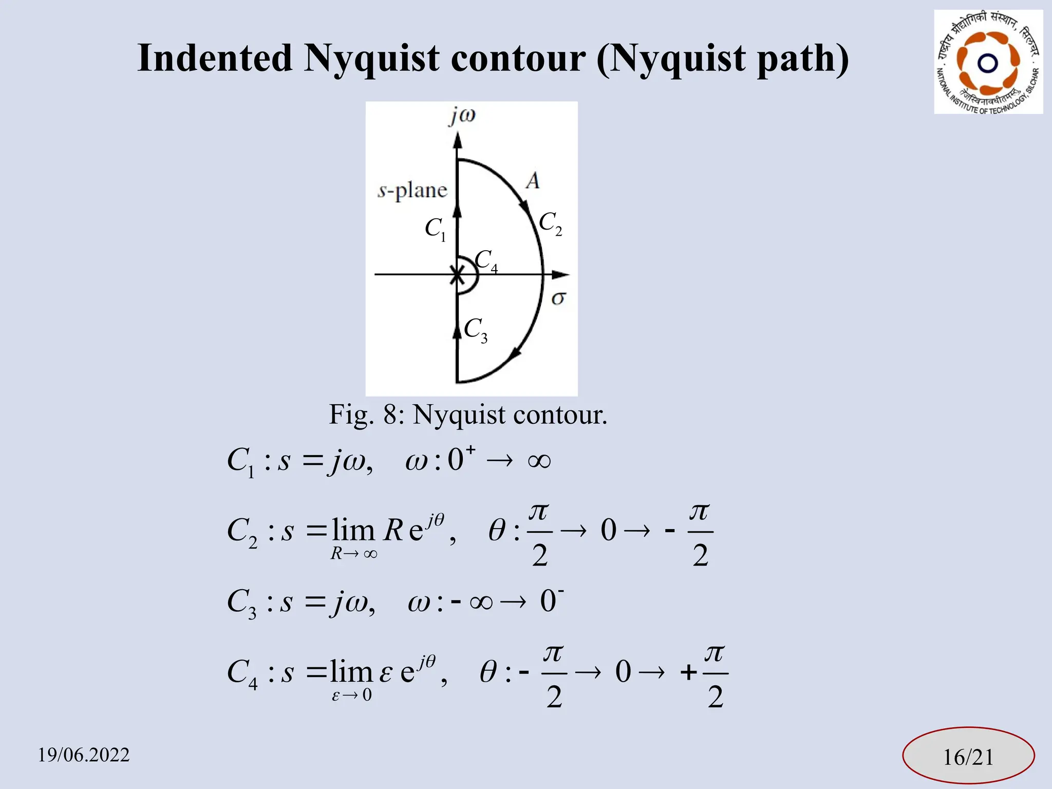
21.
Indented Nyquist contour(Nyquist path)
19/06.2022 16/21
1
2
3
4
0
: , : 0
: lim e , : 0
2 2
: , : 0
: lim e , : 0
2 2
j
R
j
C s j
C s R
C s j
C s
Fig. 8: Nyquist contour.
4
C
1
C 2
C
3
C
22.
Example-II [3]
19/06.2022 17/21
1
OLTF:( ) ( )
( 3)( 5)
G s H s
s s s
2
3
3
4
0 0
For : ( ) ( )
1 1
lim lim
Re (Re 3)(Re 5)
For : ( ) ( )
1 1
lim lim
e ( e 3)( e 5)
j
j j j
R R
j
j j j
C G s H s
e
R
C G s H s
e
Fig. 9: Nyquist contour.
1
C
2
C
3
C
4
C
3 3 1
For : Mapping of is the mirror image of about real axis.
C C C
[3] R. C. Dorf and R. H. Bishop, “Modern Control Systems”, 11th edition, Chapter 9, Pearson Education Ltd., London, UK, 2008.
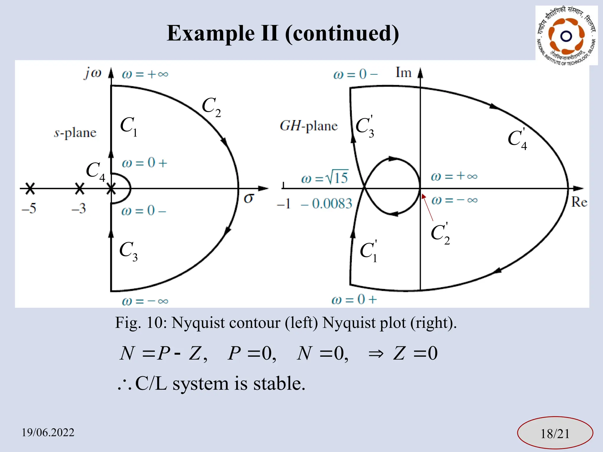
23.
Example II (continued)
19/06.202218/21
, 0, 0, 0
C/L system is stable.
N P Z P N Z
1
C
2
C
3
C
Fig. 10: Nyquist contour (left) Nyquist plot (right).
'
1
C
'
3
C '
4
C
4
C
'
2
C
24.
Points to note
1.For an O/L stable system, experimental frequency response
data may also be used in NSC.
2. However, if there is a pole-zero cancellation in the RH s-plane
then NSC is not applicable.
3. Necessary modification is required to apply NSC to extend it
to multi-va.riable system
19/06.2022 19/21
25.
Questions for evaluation
•Three contours in the s-plane are shown along with the pole-zero map of
F(s) in Fig 11a, 11b and 11c. Sketch (qualitatively) the mapping of the
contours in the F(s)-plane and also state the number of encirclement of the
origin in the F(s)-plane.
• Select suitable Nyquist contours for the following OLTFs.
19/06.2022 20/21
2
4 1 1
1. 2. 3.
1 2 2
s
s s s s s
Fig. 11a Fig. 11b Fig. 11c
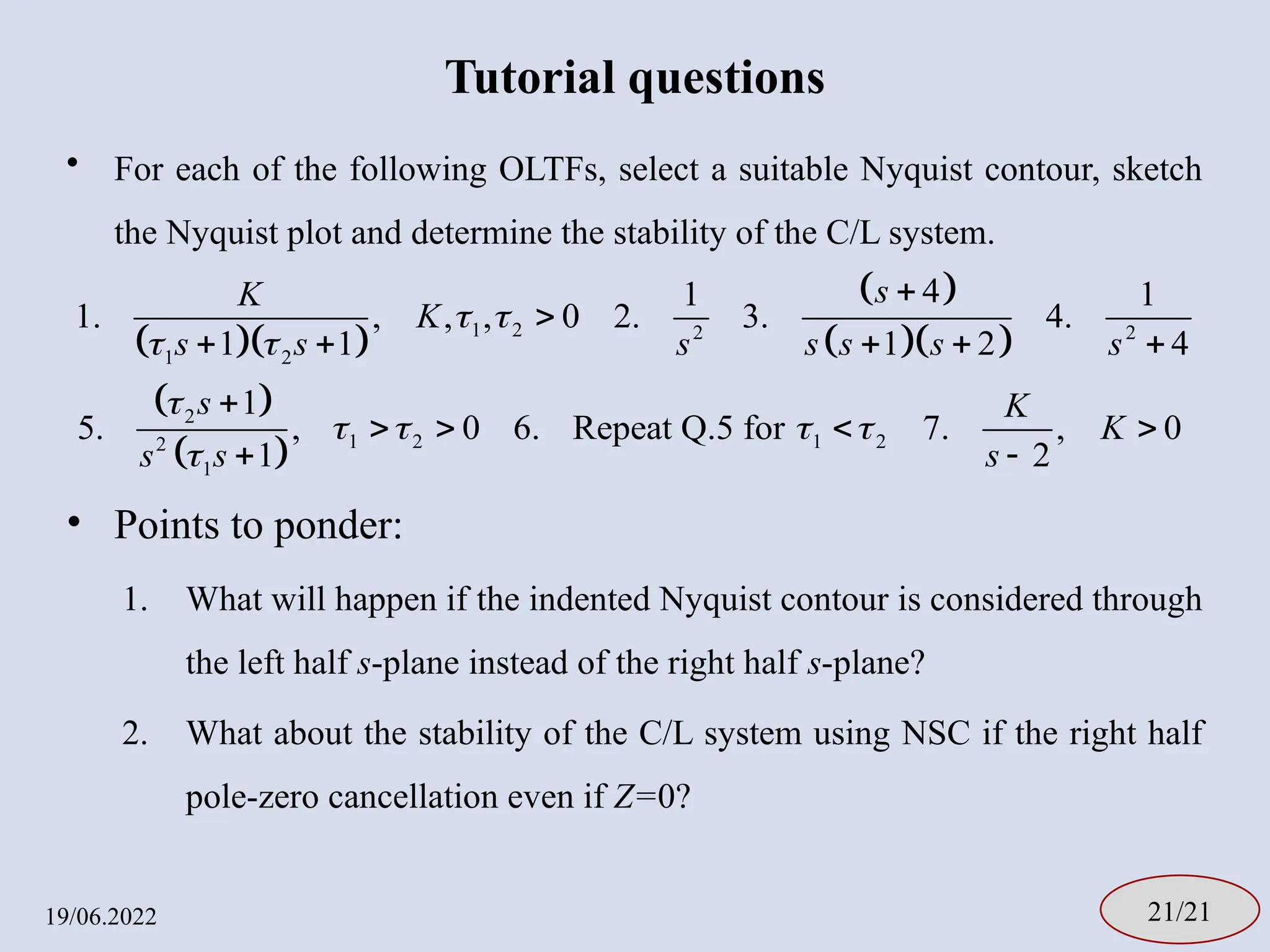
26.
Tutorial questions
• Foreach of the following OLTFs, select a suitable Nyquist contour, sketch
the Nyquist plot and determine the stability of the C/L system.
• Points to ponder:
1. What will happen if the indented Nyquist contour is considered through
the left half s-plane instead of the right half s-plane?
2. What about the stability of the C/L system using NSC if the right half
pole-zero cancellation even if Z=0?
19/06.2022 21/21
1 2 2 2
1 2
2
1 2 1 2
2
1
4
1 1
1. , , , 0 2. 3. 4.
1 1 1 2 4
1
5. , 0 6. Repeat Q.5 for 7. , 0
1 2
s
K
K
s s s s s s s
s K
K
s s s

![Principle of argument of complex variable [1]
19/06.2022 08/21
Fig. 1: Mapping of a contour from s-plane to F(s)-plane.
s
r
1
1
( )
( ) ( )
r s z F s
s z F s
Fig. 1: Mapping of a contour from s-plane to F(s)-plane.
( )
F s
( )
F s
[1] Norman S. Nise, “Control Systems Engineering”, 6th edition Chapter 11, John Wiley & Sons, Inc., Singapore, 2011.
1
1
1
( )
( ) ( )
r s p
F s
s p F s
( )
w F s
s
r
( )
w F s
( )
F s
( )
F s](https://image.slidesharecdn.com/proypresentation-250612134726-750f5d8b/75/PRoy_presentation-on-Nyquist-stability-criterion-10-2048.jpg)
![Principle of argument of complex variable [1]
19/06.2022 08/21
Fig. 1: Mapping of a contour from s-plane to F(s)-plane.
s
r
1
1
( )
( ) ( )
r s z F s
s z F s
Fig. 1: Mapping of a contour from s-plane to F(s)-plane.
( )
F s
( )
F s
[1] Norman S. Nise, “Control Systems Engineering”, 6th edition Chapter 11, John Wiley & Sons, Inc., Singapore, 2011.
1
1
1
( )
( ) ( )
r s p
F s
s p F s
( )
w F s
s
r
( )
w F s
( )
F s
( )
F s](https://image.slidesharecdn.com/proypresentation-250612134726-750f5d8b/75/PRoy_presentation-on-Nyquist-stability-criterion-11-2048.jpg)
![How to determine C/L stability? [1]
19/06.2022 12/21
1
2
3
: , :0
: lim e ,
: 0
2 2
: , : 0
j
R
C s j
C s R
C s j
1
C
2
C
3
C
Fig. 5: Nyquist contour.
[1] Norman S. Nise, “Control Systems Engineering”, 6th edition Chapter 11, John Wiley & Sons, Inc., Singapore, 2011.
1. Select Nyquist contour in the s-plane.
2. Map the contour in the G(s)H(s)-
plane.
3. Find the number of CCW
encirclement (N) of (-1+j0) point in
the G(s)H(s)-plane i.e. (0+j0) point in
the F(s)=1+G(s)H(s)-plane.
4. N=P-Z
5. For C/L stability, Z=0, i.e. N=P.](https://image.slidesharecdn.com/proypresentation-250612134726-750f5d8b/75/PRoy_presentation-on-Nyquist-stability-criterion-15-2048.jpg)
![Example-I [2]
19/06.2022 13/21
1
OLTF: ( ) ( )
( 1)( 2)
G s H s
s s
Fig. 6: Nyquist contour.
1
C 2
C
3
C
[2] Katsuhiko Ogata, “Modern Control Engineering”, 4th edition, Chapter 8, Pearson Education International, New Jersy, USA, 2002.
1 1
2 2
1
tan tan
2
1 4
1
For C : ( ) ( )
1
( 1)( 2)
G j H j
j j
s j
lim ej
R
s R
s j
](https://image.slidesharecdn.com/proypresentation-250612134726-750f5d8b/75/PRoy_presentation-on-Nyquist-stability-criterion-16-2048.jpg)
![Example-I [2]
19/06.2022 13/21
Fig. 6: Nyquist contour.
1
C 2
C
3
C
[2] Katsuhiko Ogata, “Modern Control Engineering”, 4th edition, Chapter 8, Pearson Education International, New Jersy, USA, 2002.
'
1
C
s j
lim ej
R
s R
s j
1
OLTF: ( ) ( )
( 1)( 2)
G s H s
s s
](https://image.slidesharecdn.com/proypresentation-250612134726-750f5d8b/75/PRoy_presentation-on-Nyquist-stability-criterion-17-2048.jpg)
![Example-I [2]
19/06.2022 13/21
1
OLTF: ( ) ( )
( 1)( 2)
G s H s
s s
Fig. 6: Nyquist contour.
1
C 2
C
3
C
[2] Katsuhiko Ogata, “Modern Control Engineering”, 4th edition, Chapter 8, Pearson Education International, New Jersy, USA, 2002.
2
2 2
1 1
For : ( ) ( ) lim lim
(Re 1)(Re 2)
j
j j
R R
C G s H s e
R
'
1
C
'
2
C
3 1
3
Maping of is the mirror image of the maping of
about real axis.
For : C C
C
s j
lim ej
R
s R
s j
](https://image.slidesharecdn.com/proypresentation-250612134726-750f5d8b/75/PRoy_presentation-on-Nyquist-stability-criterion-18-2048.jpg)
![Example-II [3]
19/06.2022 17/21
1
OLTF: ( ) ( )
( 3)( 5)
G s H s
s s s
2
3
3
4
0 0
For : ( ) ( )
1 1
lim lim
Re (Re 3)(Re 5)
For : ( ) ( )
1 1
lim lim
e ( e 3)( e 5)
j
j j j
R R
j
j j j
C G s H s
e
R
C G s H s
e
Fig. 9: Nyquist contour.
1
C
2
C
3
C
4
C
3 3 1
For : Mapping of is the mirror image of about real axis.
C C C
[3] R. C. Dorf and R. H. Bishop, “Modern Control Systems”, 11th edition, Chapter 9, Pearson Education Ltd., London, UK, 2008.](https://image.slidesharecdn.com/proypresentation-250612134726-750f5d8b/75/PRoy_presentation-on-Nyquist-stability-criterion-22-2048.jpg)