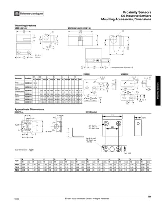
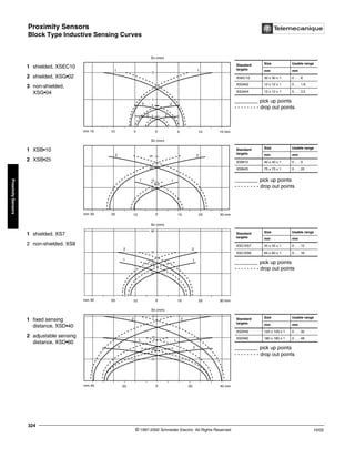
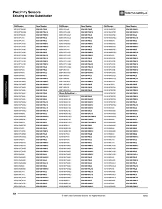
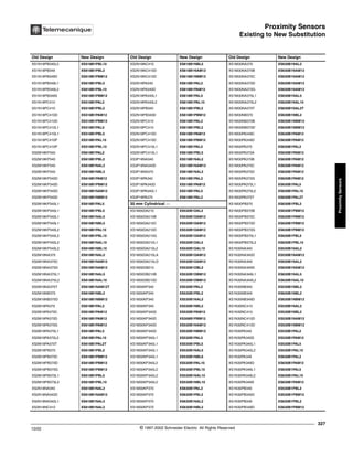
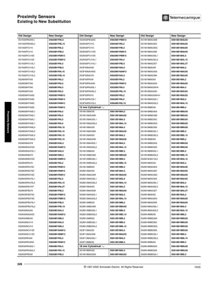
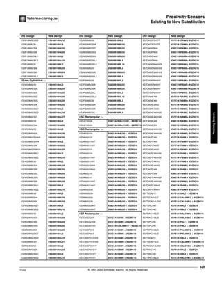
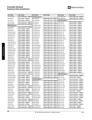
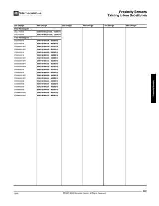
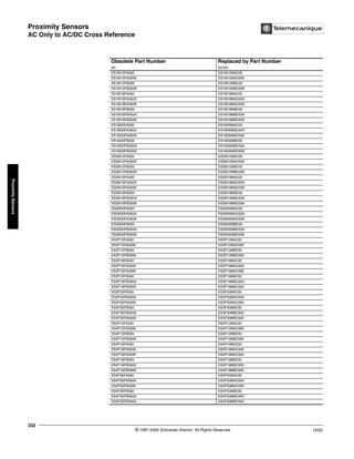
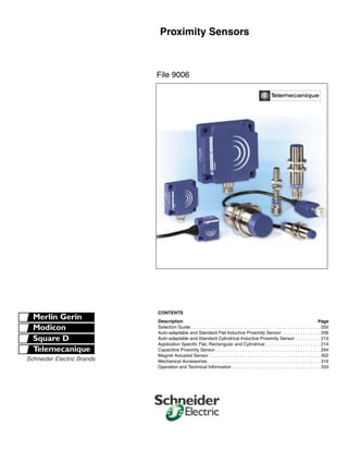
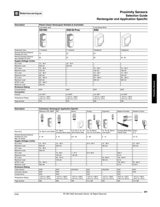
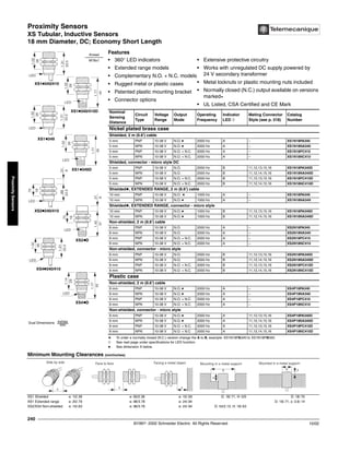
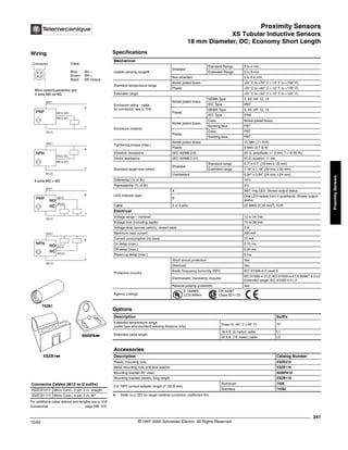
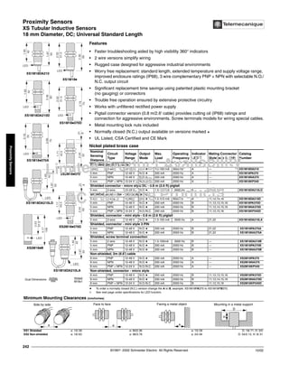
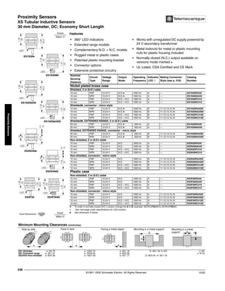
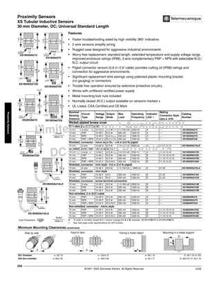
This document provides information on various proximity sensors available from Schneider Electric, including:
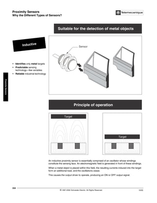
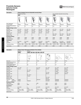
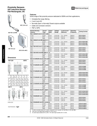
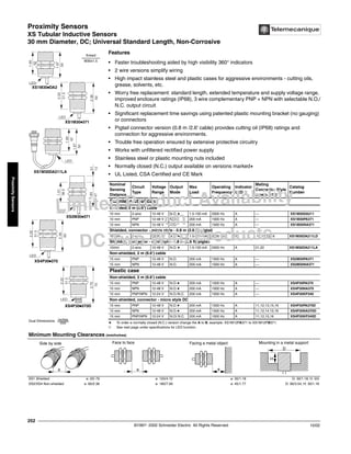
- Rectangular and cylindrical inductive proximity sensors with fixed and adjustable sensing ranges in different sizes and connection options.
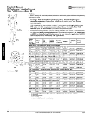
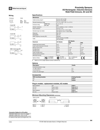
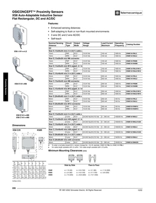
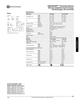
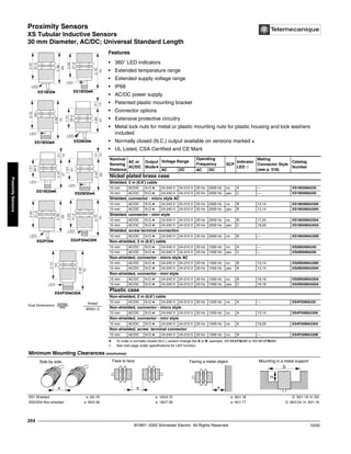
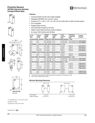
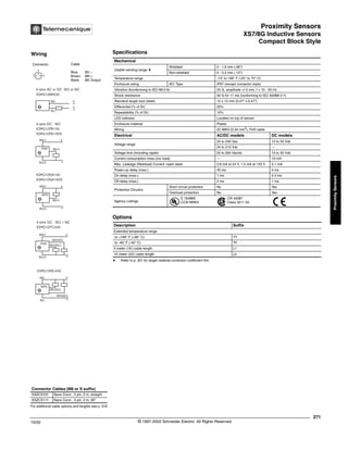
- Miniature, compact, and classic rectangular proximity sensors, both shielded and unshielded.
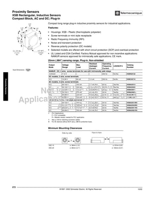
- Long range, block style, and application specific rectangular proximity sensors.
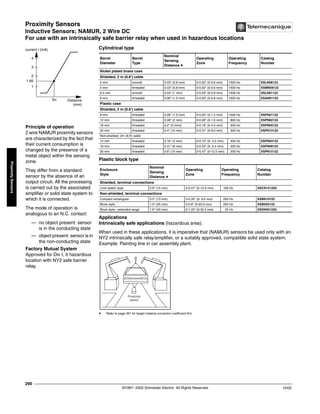
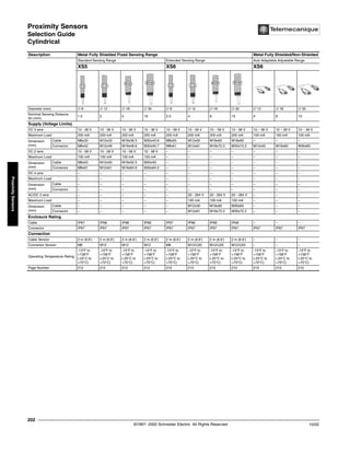
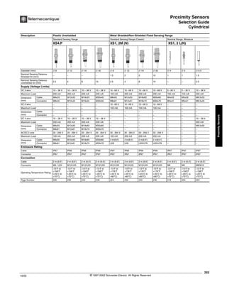
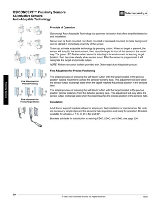
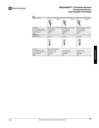
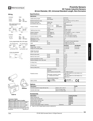
- Cylindrical proximity sensors in various barrel diameters and styles, as well as rectangular, capacitive, magnet actuated, and rotation control proximity sensors.
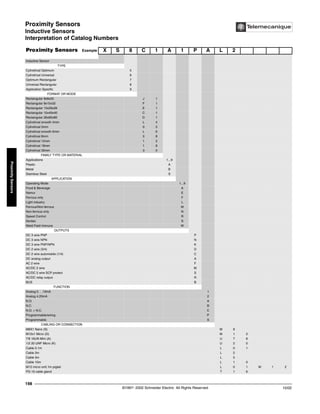
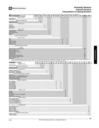
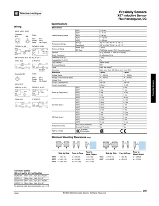
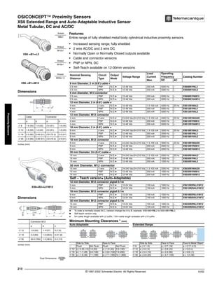
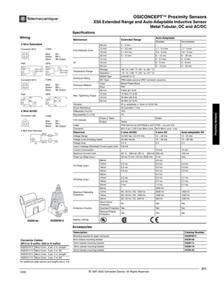
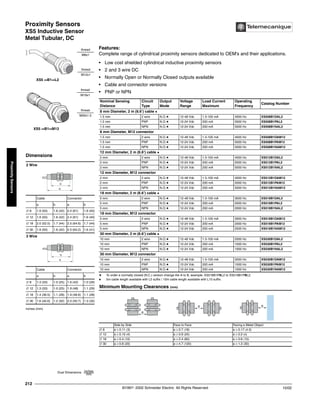
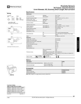
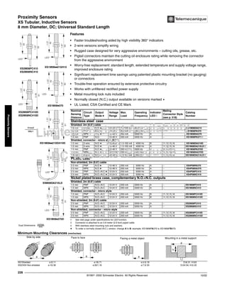
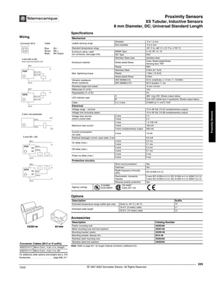
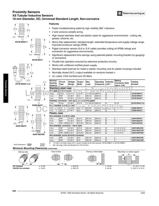
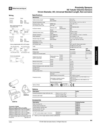
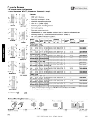
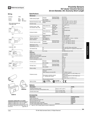
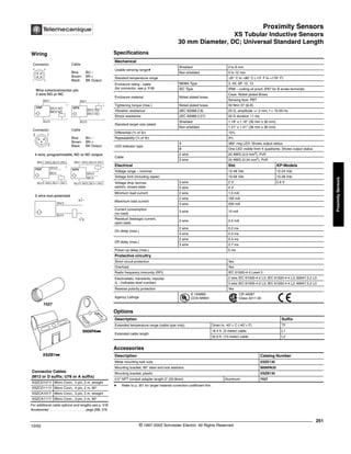
The document contains tables comparing the technical specifications of the different sensor models such as dimensions, sensing distances, operating voltages, enclosures, connections, and temperature ratings. Catalog


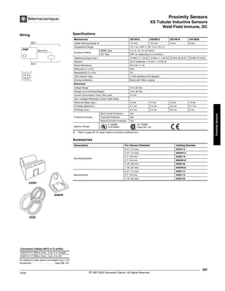
![Proximity Sensors
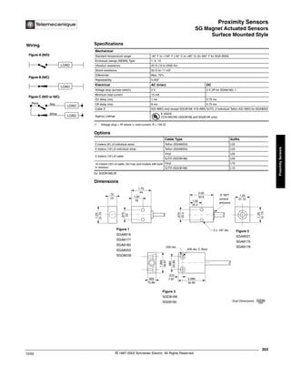
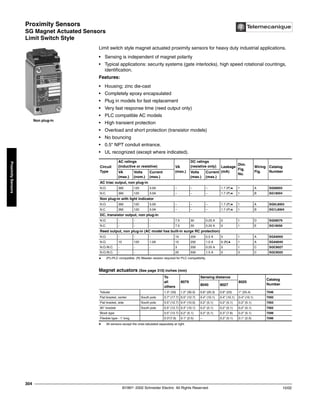
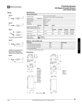
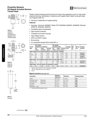
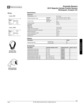
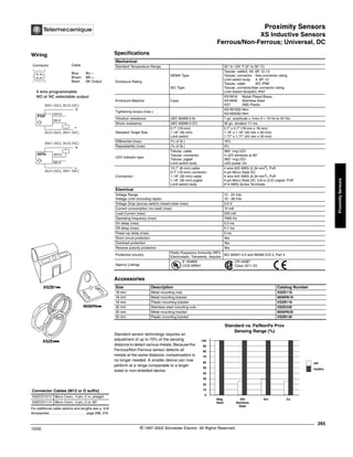
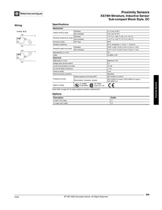
XS Tubular Inductive Sensors
Weld Field Immune, DC
©1997- 2002 Schneider Electric All Rights Reserved
286
10/02
Proximity
Sensors
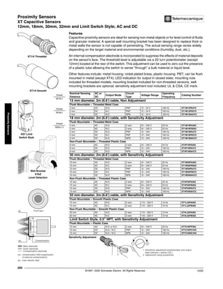
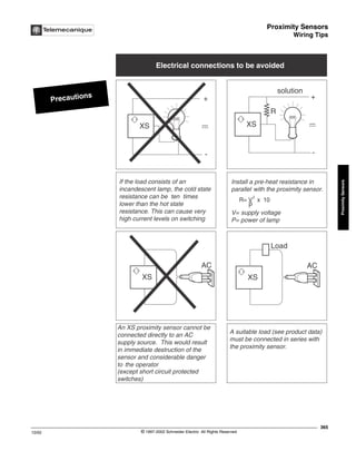
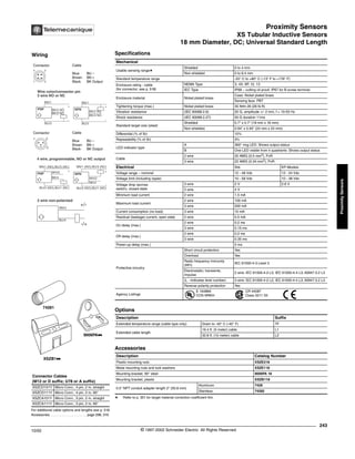
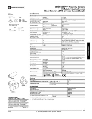
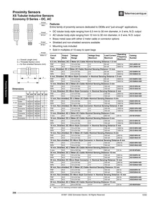
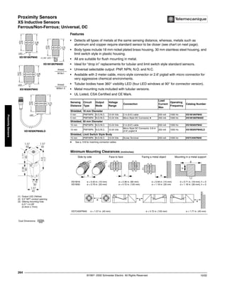
XS Tubular Inductive Sensors / Weld Field Immune, DC
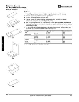
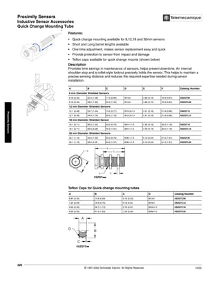
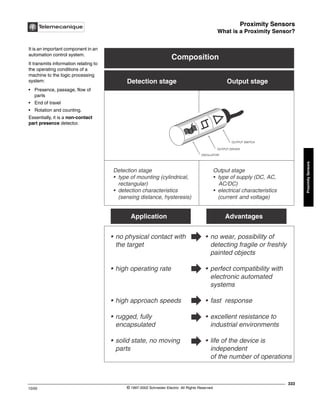
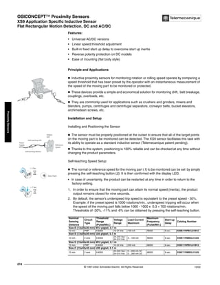
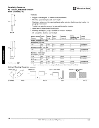
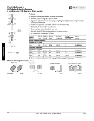
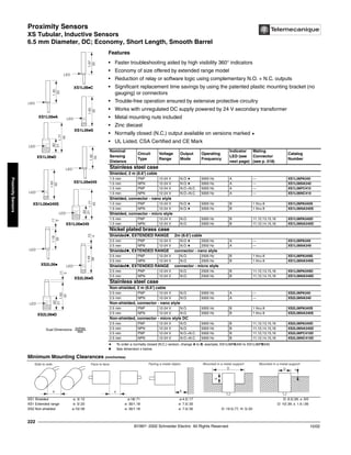
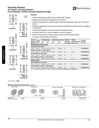
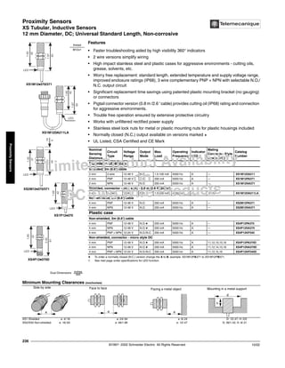
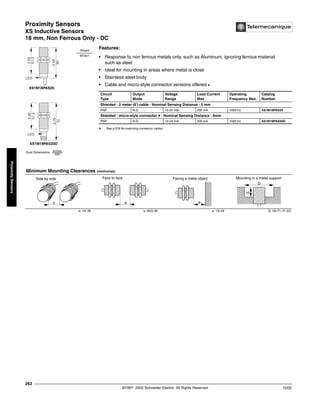
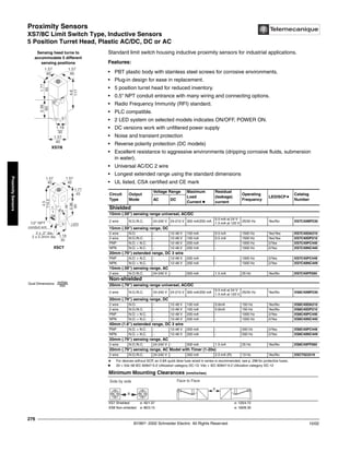
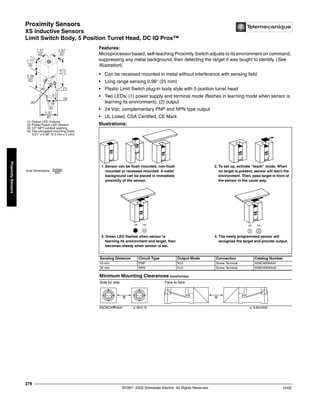
Features
Industrial welding processes create fields of electromagnetic “noise” which can interfere with
the magnetic fields of inductive proximity sensors. Standard proximity sensors can be falsely
triggered when near to these fields. WFI sensors allow uninterrupted performance when
placed extremely close to the conductor carrying the welding current.
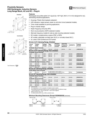
• The body styles are cylindrical in 0.47", 0.7" and 1.18" (12, 18 and 30 mm) diameters.
• Enclosure material is brass coated in Teflon®
to prevent slag (molten bits of metal) from
sticking to sensing face, reducing the possibility of false triggering.
• Available in Micro connector versions.a
• Mounting nuts included.
a See p. 518 for matching connector cables.
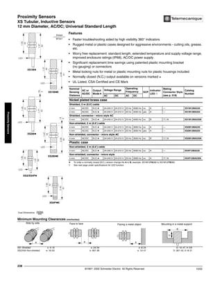
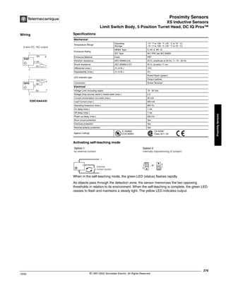
The formula below shows the relationship between distance (r [mm]) and electromagnetic flux
density (B[MT]).
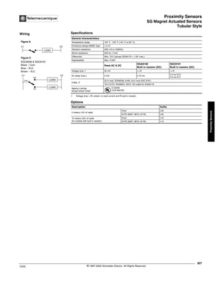
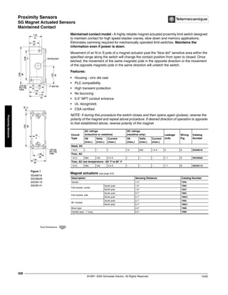
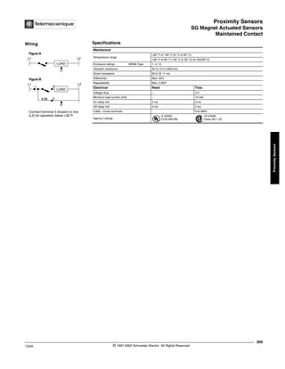
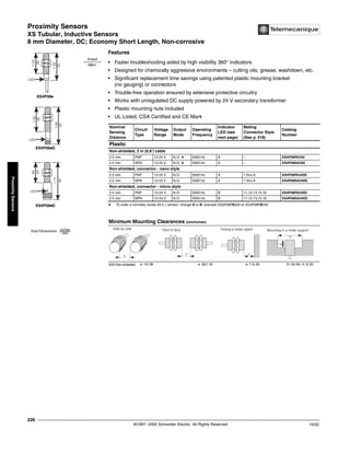
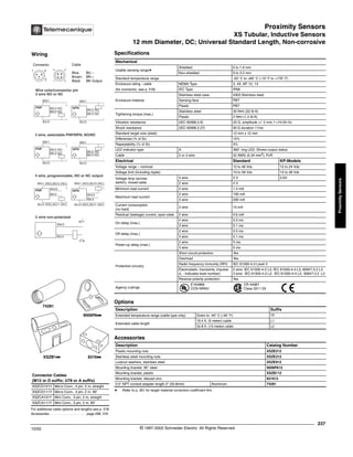
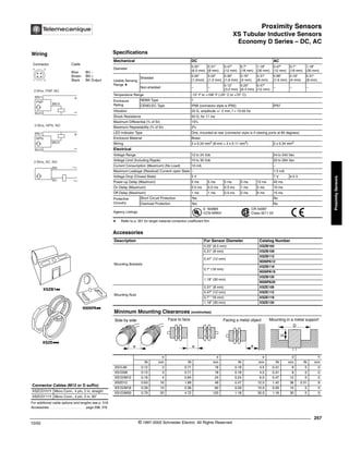
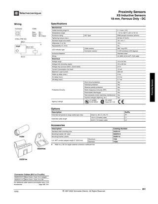
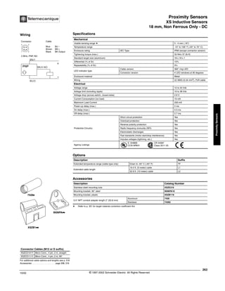
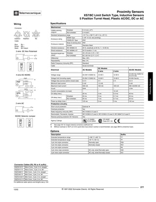
Circuit
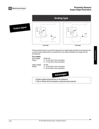
Type
Output
Mode
Voltage
Range
Voltage Drop
Maximum
Load Current
Maximum
Operating Frequency
Maximum
Catalog
Number
12 mm Shielded, DC with Micro Connector a, Nominal Sensing Distance–2 mm
PNP N.O. 10 to 36 Vdc 2.5 V 250 mA 1000 Hz XS1M12PAW01D
12 mm Non-shielded, DC with Micro Connector a, Nominal Sensing Distance–4 mm
PNP N.O. 10 to 36 Vdc 2.5 V 250 mA 1000 Hz XS2M12PAW01D
18 mm Shielded, DC with Micro Connector a, Nominal Sensing Distance–5 mm
PNP N.O. 10 to 36 Vdc 2.5 V 250 mA 500 Hz XS1M18PAW01D
30 mm Shielded, DC with Micro Connector a, Nominal Sensing Distance–10 mm
PNP N.O. 10 to 36 Vdc 2.5 V 250 mA 250 Hz XS1M30PAW01D
B [mT] = 0.2xI [A] B [mT] =
I[A] =
r [mm] =
Electromagnetic Flux Density
Welding Current
Distance
r [mm]
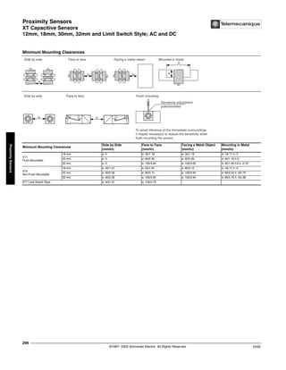
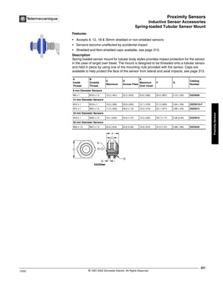
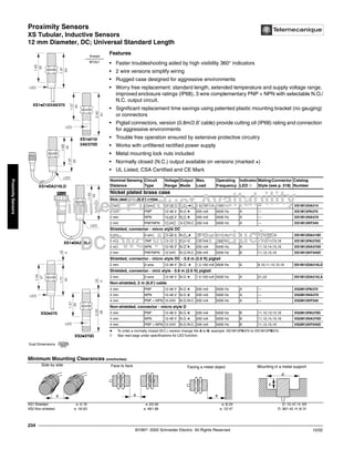
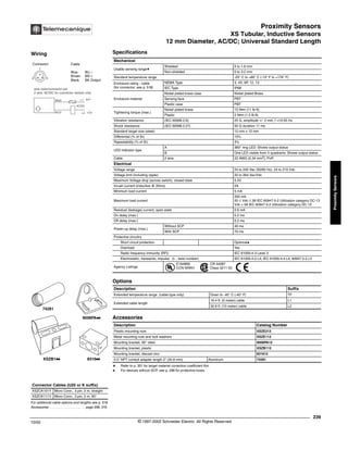
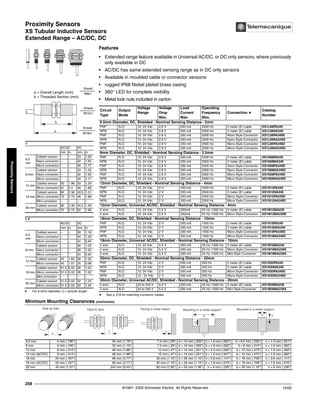
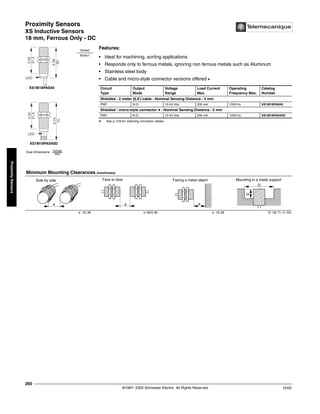
Minimum Mounting Clearances
Side by Side Face to Face Facing a Metal Object Mounted in Metal
e e e d h
IN mm IN mm IN mm IN mm IN mm
XS1M12 0 0 0.27 7 0.24 6 0.47 12 0 0
XS2M12 0.59 15 0.27 7 0.43 11 1.42 36 0.31 8
XS1M18 0 0 0.63 16 0.35 9 0.71 18 0 0
XS1M30 0 0 0.79 20 0.79 20 1.18 30 0 0
LED
LED
LED
LED
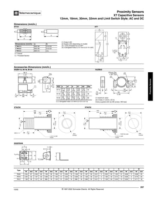
c
b
a
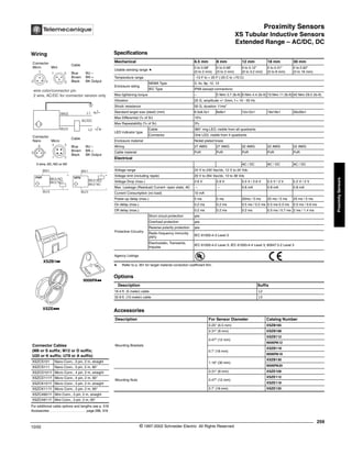
a = Overall Length (mm)
b = Threaded Section (mm)
c = for Non-shielded Sensors (mm)
a b c
XS1M12 2.3" (60) 1.6" (40) 0
XS2M12 2.3" (60) 1.5" (38) 0.16" (4)
XS1M18 2.3" (60) 1.6" (40) 0
XS1M30 2.3" (60) 1.6" (40) 0
XS1M18 XS1M30
XS1M12 XS2M12
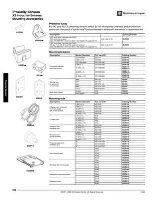
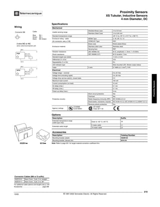
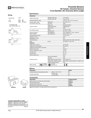
Dimensions
Side by side
e
Face to face
e
Facing a metal object
e
Mounting in a metal support
D
H](https://image.slidesharecdn.com/proximitysensordatasheet-220729155855-dd7d6a24/85/proximity-sensor-datasheet-pdf-91-320.jpg)