PROCESS
Definition :
Process isa program execution.
It is an Active entity.
Process has its own control system known as Process Control
Block (PCB)
For example,
when we write a program in C or C++ and compile it, the
compiler creates binary code. The original code and binary
code are both programs. When we actually run the binary
code, it becomes a process.
2.
PROCESS
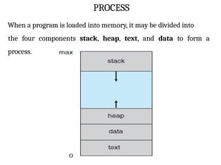
When a programis loaded into memory, it may be divided into
the four components stack, heap, text, and data to form a
process.
3.
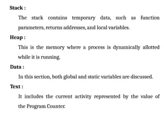
Stack :
The stackcontains temporary data, such as function
parameters, returns addresses, and local variables.
Heap :
This is the memory where a process is dynamically allotted
while it is running.
Data :
In this section, both global and static variables are discussed.
Text :
It includes the current activity represented by the value of
the Program Counter.
4.
Context Switching:
The processof saving the context of one process and loading
the context of another process is known as Context Switching.
In simple terms, it is like loading and unloading the process
from the running state to the ready state.
When Does Context Switching Happen?
1. When a high-priority process comes to a ready state (i.e.
with higher priority than the running process).
2. An Interrupt occurs.
5.
Need of ContextSwitching :
A context switching helps to share a single CPU across all processes
to complete its execution and store the system's tasks status.
6.
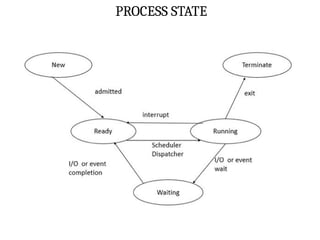
PROCESS STATE
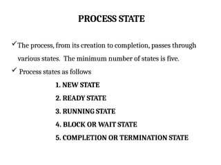
The process,from its creation to completion, passes through
various states. The minimum number of states is five.
Process states as follows
1. NEW STATE
2. READY STATE
3. RUNNING STATE
4. BLOCK OR WAIT STATE
5. COMPLETION OR TERMINATION STATE
7.
PROCESS STATE
NEW STATE:
The process is being created.
It means a new process that has been created. But has not
yet been admitted by the OS for its execution.
8.
PROCESS STATE
READY STATE:
Whenever a process is created, it directly enters in the ready
state.
it waits for the CPU(running) to be assigned.
The OS picks the new processes from the secondary memory
and put all of them in the main memory.
This state contains Ready queue for waiting the processes.
9.
PROCESS STATE
RUNNING STATE:
Instructions are being executed.
The process is chosen from the ready queue by the CPU for
execution.
10.
PROCESS STATE
BLOCK ORWAIT STATE:
The process is in waiting state until an event occurs like I/O
operation completion or receiving a signal.
When a process waits for a certain resource or waits for
the input from the user then the OS move this process from
running state to block or wait state and assigns the CPU to
the other processes.
11.
PROCESS STATE
TERMINATED STATE:
When a process finishes its execution or a process kills,
it moves from running state to termination state.
PROCESS CONTROL BLOCK
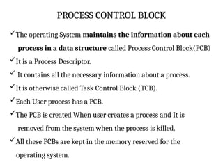
Theoperating System maintains the information about each
process in a data structure called Process Control Block(PCB)
It is a Process Descriptor.
It contains all the necessary information about a process.
It is otherwise called Task Control Block (TCB).
Each User process has a PCB.
The PCB is created When user creates a process and It is
removed from the system when the process is killed.
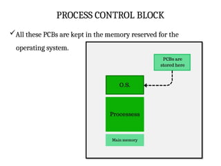
All these PCBs are kept in the memory reserved for the
operating system.
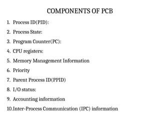
COMPONENTS OF PCB
1.Process ID(PID):
2. Process State:
3. Program Counter(PC):
4. CPU registers:
5. Memory Management Information
6. Priority
7. Parent Process ID(PPID)
8. I/O status:
9. Accounting information
10.Inter-Process Communication (IPC) information
16.
COMPONENTS OF PCB
1.Process ID(PID):
It is unique identification of the process.
It is assigned by os when process is created.
It helps to differentiate between processes.
17.
COMPONENTS OF PCB
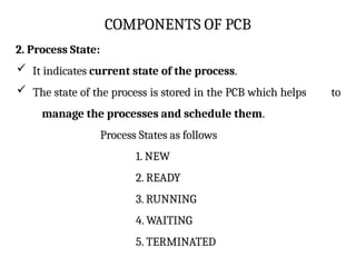
2.Process State:
It indicates current state of the process.
The state of the process is stored in the PCB which helps to
manage the processes and schedule them.
Process States as follows
1. NEW
2. READY
3. RUNNING
4. WAITING
5. TERMINATED
18.
COMPONENTS OF PCB
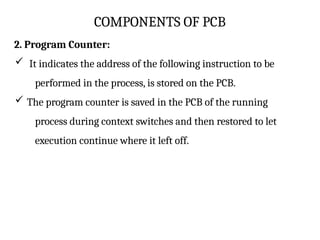
2.Program Counter:
It indicates the address of the following instruction to be
performed in the process, is stored on the PCB.
The program counter is saved in the PCB of the running
process during context switches and then restored to let
execution continue where it left off.
19.
COMPONENTS OF PCB
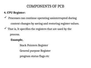
4.CPU Register:
Processes can continue operating uninterrupted during
context changes by saving and restoring register values.
That is, It specifies the registers that are used by the
process.
Example,
Stack Pointers Register
General purpose Register
program status flags etc
20.
COMPONENTS OF PCB
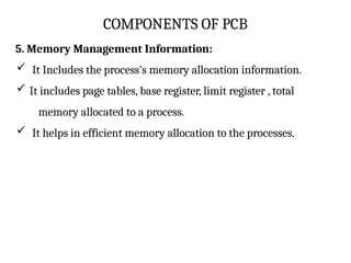
5.Memory Management Information:
It Includes the process's memory allocation information.
It includes page tables, base register, limit register , total
memory allocated to a process.
It helps in efficient memory allocation to the processes.
21.
COMPONENTS OF PCB
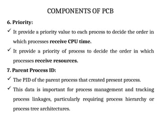
6.Priority:
It provide a priority value to each process to decide the order in
which processes receive CPU time.
It provide a priority of process to decide the order in which
processes receive resources.
7. Parent Process ID:
The PID of the parent process that created present process.
This data is important for process management and tracking
process linkages, particularly requiring process hierarchy or
process tree architectures.
22.
COMPONENTS OF PCB
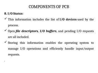
8.I/O Status:
This information includes the list of I/O devices used by the
process.
Open file descriptors, I/O buffers, and pending I/O requests
are all included.
Storing this information enables the operating system to
manage I/O operations and efficiently handle input/output
requests.
.
23.
COMPONENTS OF PCB
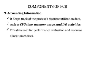
9.Accounting Information:
It Keeps track of the process's resource utilization data.
such as CPU time, memory usage, and I/O activities.
This data used for performance evaluation and resource
allocation choices.
24.
COMPONENTS OF PCB
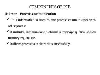
10.Inter – Process Communication :
This information is used to one process communicates with
other process.
It includes communication channels, message queues, shared
memory regions etc.
It allows processes to share data successfully.
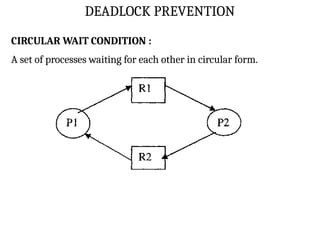
DEADLOCK
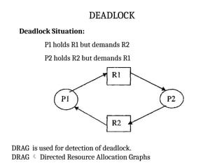
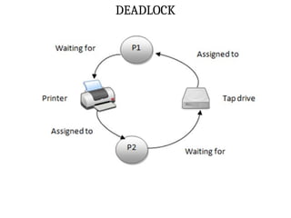
Deadlock Situation:
P1 holdsR1 but demands R2
P2 holds R2 but demands R1
DRAG is used for detection of deadlock.
DRAG Directed Resource Allocation Graphs
27.
DEADLOCK
Example,
Let us imaginetwo processes :P1 and P2
P1 and P2 running simultaneously.
Now,
P1 requests the operating system for a file on tape drive.
P2 requests the operating system for printer.
Let us assume that both the requests are granted.
28.
DEADLOCK
Now,
P1 requests forprinter without giving up the tape drive
Similarly , P2 requests for the tape drive without giving
up the control of the printer.
Assuming that the system has only one tape drive and one
Printer.
Now, What will happen?
It is clear that both the processes cannot proceed.
P1 will wait until P2 releases the printer.
P2 will wait until P1 releases the tape drive. So both processes
are blocked . This situation is called DEADLOCK.
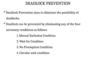
DEADLOCK PREVENTION
Deadlock Preventionaims to eliminate the possibility of
deadlocks.
Deadlock can be prevented by eliminating any of the four
necessary conditions as follows:
1. Mutual Exclusion Condition
2. Wait for Condition
3. No Preemption Condition
4. Circular wait condition
31.
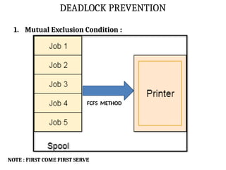
DEADLOCK PREVENTION
1. MutualExclusion Condition :
The mutual Exclusion condition must hold for
non-sharable types of resources.(Only one process can use
at a time)
Example, PRINTER.
DEADLOCK PREVENTION
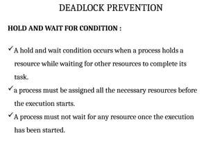
HOLD ANDWAIT FOR CONDITION :
A hold and wait condition occurs when a process holds a
resource while waiting for other resources to complete its
task.
a process must be assigned all the necessary resources before
the execution starts.
A process must not wait for any resource once the execution
has been started.
34.
DEADLOCK PREVENTION
NO PREMPTION:
Once a process is holding a resource ( i.e. once its request has been
granted ), then that resource cannot be taken away from that
process until the process voluntarily releases it.
DEADLOCK AVOIDENCE
Deadlockavoidance is another technique used in operating
systems to deal with deadlocks.
deadlock avoidance focuses on dynamically detecting and
avoiding situations that could lead to deadlocks.
It is a banker algorithm used to avoid deadlock and allocate
resources safely to each process in the computer system.
37.
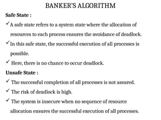
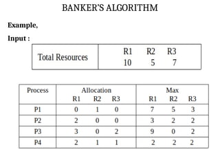
BANKER’S ALGORITHM
Safe State:
A safe state refers to a system state where the allocation of
resources to each process ensures the avoidance of deadlock.
In this safe state, the successful execution of all processes is
possible.
Here, there is no chance to occur deadlock.
Unsafe State :
The successful completion of all processes is not assured.
The risk of deadlock is high.
The system is insecure when no sequence of resource
allocation ensures the successful execution of all processes.
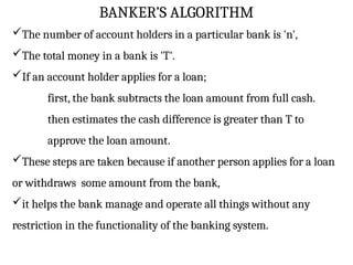
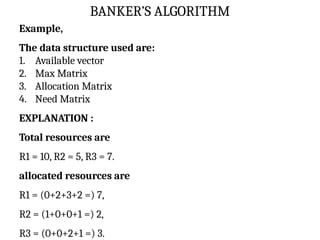
BANKER’S ALGORITHM
The numberof account holders in a particular bank is 'n',
The total money in a bank is 'T'.
If an account holder applies for a loan;
first, the bank subtracts the loan amount from full cash.
then estimates the cash difference is greater than T to
approve the loan amount.
These steps are taken because if another person applies for a loan
or withdraws some amount from the bank,
it helps the bank manage and operate all things without any
restriction in the functionality of the banking system.
40.
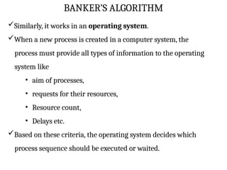
BANKER’S ALGORITHM
Similarly, itworks in an operating system.
When a new process is created in a computer system, the
process must provide all types of information to the operating
system like
• aim of processes,
• requests for their resources,
• Resource count,
• Delays etc.
Based on these criteria, the operating system decides which
process sequence should be executed or waited.
41.
BANKER’S ALGORITHM
so thatno deadlock occurs in a system.
Therefore, it is also known as deadlock avoidance algorithm in
the operating system.
42.
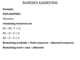
BANKER’S ALGORITHM
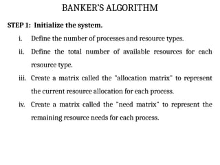
STEP 1:Initialize the system.
i. Define the number of processes and resource types.
ii. Define the total number of available resources for each
resource type.
iii. Create a matrix called the "allocation matrix" to represent
the current resource allocation for each process.
iv. Create a matrix called the "need matrix" to represent the
remaining resource needs for each process.
43.
BANKER’S ALGORITHM
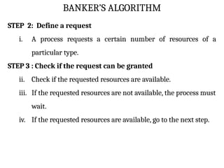
STEP 2:Define a request
i. A process requests a certain number of resources of a
particular type.
STEP 3 : Check if the request can be granted
ii. Check if the requested resources are available.
iii. If the requested resources are not available, the process must
wait.
iv. If the requested resources are available, go to the next step.
44.
BANKER’S ALGORITHM
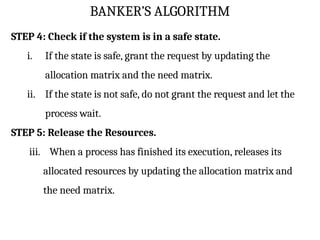
STEP 4:Check if the system is in a safe state.
i. If the state is safe, grant the request by updating the
allocation matrix and the need matrix.
ii. If the state is not safe, do not grant the request and let the
process wait.
STEP 5: Release the Resources.
iii. When a process has finished its execution, releases its
allocated resources by updating the allocation matrix and
the need matrix.
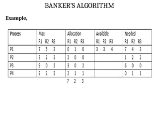
BANKER’S ALGORITHM
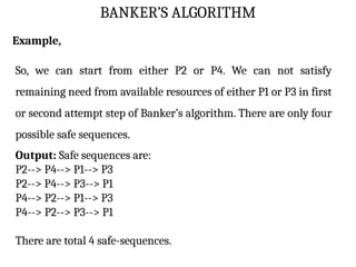
Example,
So, wecan start from either P2 or P4. We can not satisfy
remaining need from available resources of either P1 or P3 in first
or second attempt step of Banker’s algorithm. There are only four
possible safe sequences.
Output: Safe sequences are:
P2--> P4--> P1--> P3
P2--> P4--> P3--> P1
P4--> P2--> P1--> P3
P4--> P2--> P3--> P1
There are total 4 safe-sequences.
50.
PROCESS SCHEDULING
Theprocess scheduling is the activity of the process manager.
It selects the process for running to the CPU based on
scheduling method.
It handles the removal of the running process from the CPU.
Process scheduling is an essential part of a Multiprogramming
operating systems.
Such operating systems allow more than one process to be
loaded into the executable memory at a time
SCHEDULING PHILOSOPHIES
1. PREEMPTIVESCHEDULING :
It allows High priority process get first priority for running.
In this case, the current process switches from the running state
to ready queue.
The high priority process utilizes the CPU cycle.
2. NON-PREEMPTIVE SCHEDULING :
Any new process or High priority process has to wait until the
running process finishes its CPU utilization.
53.
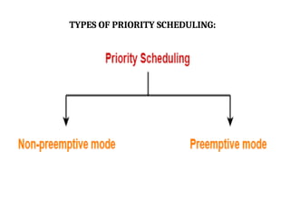
TYPES OF PROCESSSCHEDULING
There are basically 3 types of scheduling
1. LONG TERM SCHEDULING
2. MEDIUM TERM SCHEDULING
3. SHORT TERM SCHEDULING
54.
TYPES OF PROCESSSCHEDULING
LONG TERM SCHEDULING :
Long term scheduler is also known as job scheduler.
A long-term scheduler is a scheduler that is responsible for
bringing processes from the JOB queue (or secondary
memory) into the READY queue (or main memory).
It determines which processes should be admitted to the
system and when.
A long-term scheduler’s primary function is to minimize
processing time by taking the mixtures of CPU-bound jobs and
I/O-bound jobs.
It controls Multiprogramming degree.
55.
TYPES OF PROCESSSCHEDULING
It always present in Batch OS.
CPU Bound Job :
CPU-bound jobs are tasks or processes that necessitate a
particular amount of CPU processing time and resources.
I/O Bound Job :
I/O bound jobs are tasks or processes that necessitate a large
number of input/output (I/O) operations, such as reading and
writing to discs or networks.
Multiprogramming degree :
It describes the maximum number of processes that a single-
processor system can accommodate efficiently
56.
SHORT TERM SCHEDULAR:
Short term scheduler is also known as CPU Scheduler.
The short-term scheduler's main job is to choose a process
from the Ready Queue that is ready to run and assign the
processor to it.
It is faster compare than Long term schedular.
Some Short Term scheduler policy:
First Come, First Serve (FCFS) policy
Shortest Job First policy
Priority scheduling policy
Round Robin scheduling policy
57.
TYPES OF PROCESSSCHEDULING
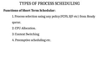
Functions of Short Term Schedular:
1. Process selection using any policy(FCFS, SJF etc) from Ready
queue.
2. CPU Allocation.
3. Context Switching
4. Preemptive scheduling etc.
58.
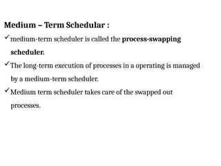
Medium – TermSchedular :
medium-term scheduler is called the process-swapping
scheduler.
The long-term execution of processes in a operating is managed
by a medium-term scheduler.
Medium term scheduler takes care of the swapped out
processes.
59.
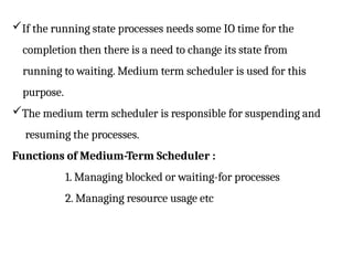
If the runningstate processes needs some IO time for the
completion then there is a need to change its state from
running to waiting. Medium term scheduler is used for this
purpose.
The medium term scheduler is responsible for suspending and
resuming the processes.
Functions of Medium-Term Scheduler :
1. Managing blocked or waiting-for processes
2. Managing resource usage etc
61.
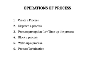
OPERATIONS OF PROCESS
1.Create a Process.
2. Dispatch a process.
3. Process premption (or) Time up the process
4. Block a process
5. Wake-up a process.
6. Process Termination
62.
OPERATIONS OF PROCESS
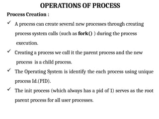
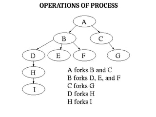
ProcessCreation :
A process can create several new processes through creating
process system calls (such as fork() ) during the process
execution.
Creating a process we call it the parent process and the new
process is a child process.
The Operating System is identify the each process using unique
process Id.(PID).
The init process (which always has a pid of 1) serves as the root
parent process for all user processes.
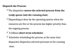
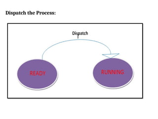
Dispatch the Process:
Thedispatcher moves the selected process from the
ready queue into the running state.
Dispatching is done by the operating system when the
resources are free or the process has higher priority than
the ongoing process.
It follows short-term schedular.
Scheduler scheduling the process, at the same time
dispatcher dispatches selected processes to the running
state.
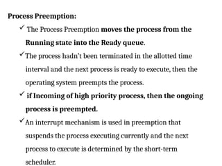
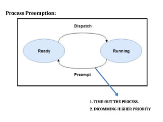
Process Preemption:
TheProcess Preemption moves the process from the
Running state into the Ready queue.
The process hadn’t been terminated in the allotted time
interval and the next process is ready to execute, then the
operating system preempts the process.
if Incoming of high priority process, then the ongoing
process is preempted.
An interrupt mechanism is used in preemption that
suspends the process executing currently and the next
process to execute is determined by the short-term
scheduler.
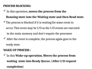
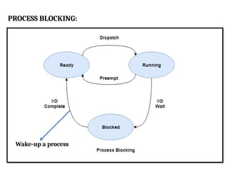
PROCESS BLOCKING:
Inthis operation, moves the process from the
Running state into the Waiting state and then Read state.
The process is blocked if it is waiting for some event to
occur. This event may be I/O as the I/O events are executed
in the main memory and don't require the processor.
After the event is complete, the process again goes to the
ready state.
WAKE-UP PROCESS :
In this Wake-up operation, Moves the process from
waiting state into Ready Queue. (After I/O request
completion)
PROCESS TERMINATION :
After the process has completed the execution of its last
instruction, it is terminated.
The resources held by a process are released after it is
terminated.
The exit( ) system call is used for process termination.
In this operation, moves the process from the
Running state into Terminate State.
71.
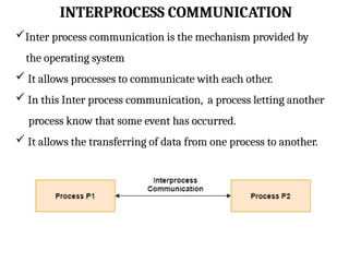
INTERPROCESS COMMUNICATION
Inter processcommunication is the mechanism provided by
the operating system
It allows processes to communicate with each other.
In this Inter process communication, a process letting another
process know that some event has occurred.
It allows the transferring of data from one process to another.
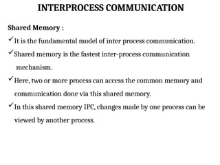
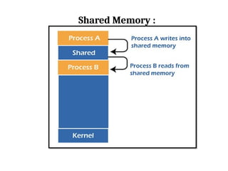
INTERPROCESS COMMUNICATION
Shared Memory:
It is the fundamental model of inter process communication.
Shared memory is the fastest inter-process communication
mechanism.
Here, two or more process can access the common memory and
communication done via this shared memory.
In this shared memory IPC, changes made by one process can be
viewed by another process.
74.
INTERPROCESS COMMUNICATION
Shared Memory:
Each process has its own address space;
if any process wants to communicate with some information
from its own address space to other processes, then it is only
possible with IPC (inter-process communication) techniques.
75.
INTERPROCESS COMMUNICATION
Advantage ofShared Memory :
Shared memory is a faster inter process communication system.
It is most suitable technique for exchange large amounts of data
It allows cooperating processes to access the same pieces of data
concurrently.
Users can perform multiple tasks at a time.
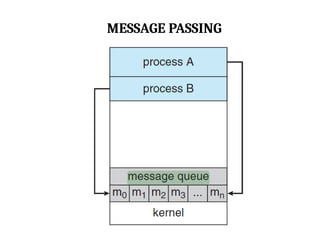
MESSAGE PASSING
Message passingis a method of Inter Process Communication
in OS.
It is used to the exchange of messages between processes.
Each process sends and receives messages to coordinate its
activities and exchange data with other processes.
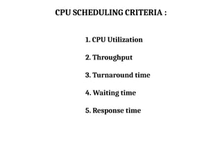
CPU SCHEDULING CRITERIA:
1. CPU Utilization
2. Throughput
3. Turnaround time
4. Waiting time
5. Response time
80.
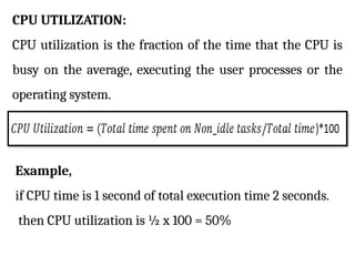
CPU UTILIZATION:
CPU utilizationis the fraction of the time that the CPU is
busy on the average, executing the user processes or the
operating system.
Example,
if CPU time is 1 second of total execution time 2 seconds.
then CPU utilization is ½ x 100 = 50%
81.
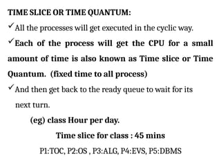
TIME SLICE ORTIME QUANTUM:
All the processes will get executed in the cyclic way.
Each of the process will get the CPU for a small
amount of time is also known as Time slice or Time
Quantum. (fixed time to all process)
And then get back to the ready queue to wait for its
next turn.
(eg) class Hour per day.
Time slice for class : 45 mins
P1:TOC, P2:OS , P3:ALG, P4:EVS, P5:DBMS
82.
THROUGHPUT:
It means ‘Numberof processes completed per unit
time’
For long process, this rate may be one process per
hour
for short transactions, throughput might be 10
process per second.
83.
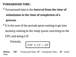
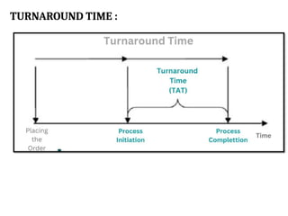
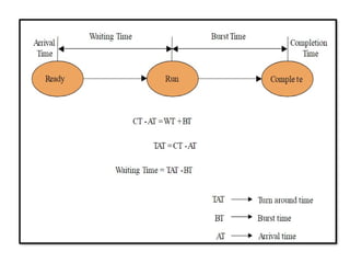
TURNAROUND TIME :
Turnaroundtime is the interval from the time of
submission to the time of completion of a
process.
It is the sum of the periods spent waiting to get into
memory, waiting in the ready queue, executing on the
CPU, and doing I/O
Formula,
Where, TAT Turnaround Time, CT Completion Time , ATArival
Time
ARRIVAL TIME :
Thetime at which the process enters into the ready queue is called
the arrival time.
COMPLETION TIME :
The Time at which the process enters into the completion state
(or)
The time at which the process completes its execution, is called
completion time.
87.
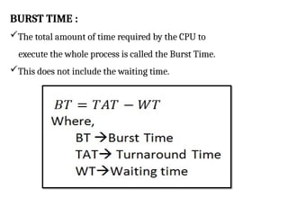
BURST TIME :
Thetotal amount of time required by the CPU to
execute the whole process is called the Burst Time.
This does not include the waiting time.
88.
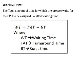
WAITING TIME :
TheTotal amount of time for which the process waits for
the CPU to be assigned is called waiting time.
89.
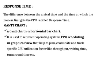
RESPONSE TIME :
Thedifference between the arrival time and the time at which the
process first gets the CPU is called Response Time.
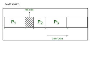
GANTT CHART :
A Gantt chart is a horizontal bar chart.
It is used to represent operating systems CPU scheduling
in graphical view that help to plan, coordinate and track
specific CPU utilization factor like throughput, waiting time,
turnaround time etc.
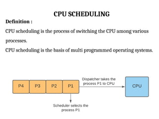
CPU SCHEDULING
Definition :
CPUscheduling is the process of switching the CPU among various
processes.
CPU scheduling is the basis of multi programmed operating systems.
92.
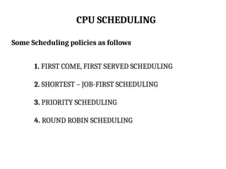
CPU SCHEDULING
Some Schedulingpolicies as follows
1. FIRST COME, FIRST SERVED SCHEDULING
2. SHORTEST – JOB-FIRST SCHEDULING
3. PRIORITY SCHEDULING
4. ROUND ROBIN SCHEDULING
93.
CPU SCHEDULING
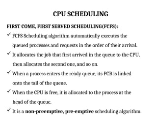
FIRST COME,FIRST SERVED SCHEDULING(FCFS):
FCFS Scheduling algorithm automatically executes the
queued processes and requests in the order of their arrival.
It allocates the job that first arrived in the queue to the CPU,
then allocates the second one, and so on.
When a process enters the ready queue, its PCB is linked
onto the tail of the queue.
When the CPU is free, it is allocated to the process at the
head of the queue.
It is a non-preemptive, pre-emptive scheduling algorithm.
94.
CPU SCHEDULING
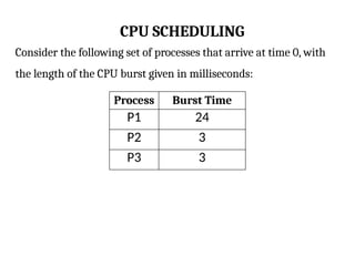
Consider thefollowing set of processes that arrive at time 0, with
the length of the CPU burst given in milliseconds:
Process Burst Time
P1 24
P2 3
P3 3
95.
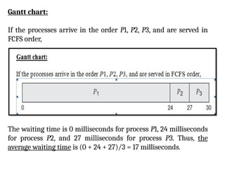
Gantt chart:
If theprocesses arrive in the order P1, P2, P3, and are served in
FCFS order,
The waiting time is 0 milliseconds for process P1, 24 milliseconds
for process P2, and 27 milliseconds for process P3. Thus, the
average waiting time is (0 + 24 + 27)/3 = 17 milliseconds.
96.
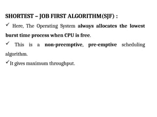
SHORTEST – JOBFIRST ALGORITHM(SJF) :
Here, The Operating System always allocates the lowest
burst time process when CPU is free.
This is a non-preemptive, pre-emptive scheduling
algorithm.
It gives maximum throughput.
97.
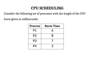
CPU SCHEDULING
Consider thefollowing set of processes with the length of the CPU
burst given in milliseconds:
Process Burst Time
P1 6
P2 8
P3 7
P4 3
98.
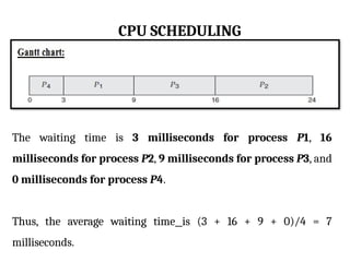
CPU SCHEDULING
The waitingtime is 3 milliseconds for process P1, 16
milliseconds for process P2, 9 milliseconds for process P3, and
0 milliseconds for process P4.
Thus, the average waiting time is (3 + 16 + 9 + 0)/4 = 7
milliseconds.
99.
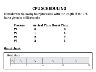
CPU SCHEDULING
Consider thefollowing four processes, with the length of the CPU
burst given in milliseconds:
Process Arrival Time Burst Time
P1 0 8
P2 1 4
P3 2 9
P4 3 5
Gantt chart:
100.
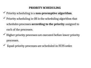
PRIORITY SCHEDULING
Priorityscheduling is a non-preemptive algorithm.
Priority scheduling in OS is the scheduling algorithm that
schedules processes according to the priority assigned to
each of the processes.
Higher priority processes are executed before lower priority
processes.
Equal-priority processes are scheduled in FCFS order.
101.
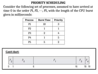
PRIORITY SCHEDULING
Consider thefollowing set of processes, assumed to have arrived at
time 0 in the order P1, P2, · · ·, P5, with the length of the CPU burst
given in milliseconds:
Process Burst Time Priority
P1 10 3
P2 1 1
P3 2 4
P4 1 5
P5 5 2
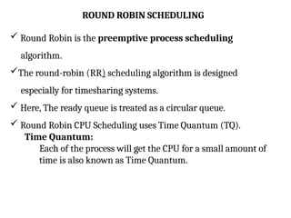
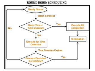
ROUND ROBIN SCHEDULING
Round Robin is the preemptive process scheduling
algorithm.
The round-robin (RR) scheduling algorithm is designed
especially for timesharing systems.
Here, The ready queue is treated as a circular queue.
Round Robin CPU Scheduling uses Time Quantum (TQ).
Time Quantum:
Each of the process will get the CPU for a small amount of
time is also known as Time Quantum.
104.
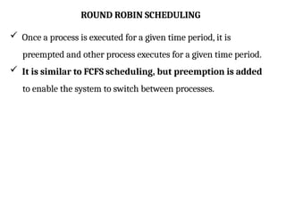
ROUND ROBIN SCHEDULING
Once a process is executed for a given time period, it is
preempted and other process executes for a given time period.
It is similar to FCFS scheduling, but preemption is added
to enable the system to switch between processes.
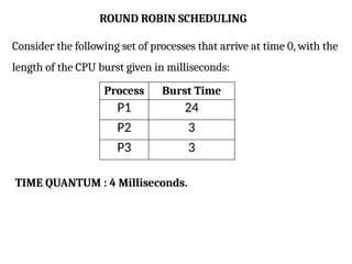
ROUND ROBIN SCHEDULING
Considerthe following set of processes that arrive at time 0, with the
length of the CPU burst given in milliseconds:
Process Burst Time
P1 24
P2 3
P3 3
TIME QUANTUM : 4 Milliseconds.
107.
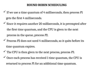
ROUND ROBIN SCHEDULING
If we use a time quantum of 4 milliseconds, then process P1
gets the first 4 milliseconds.
Since it requires another 20 milliseconds, it is preempted after
the first time quantum, and the CPU is given to the next
process in the queue, process P2.
Process P2 does not need 4 milliseconds, so it quits before its
time quantum expires.
The CPU is then given to the next process, process P3.
Once each process has received 1 time quantum, the CPU is
returned to process P1 for an additional time quantum.
108.
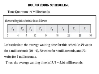
ROUND ROBIN SCHEDULING
TimeQuantum : 4 Milliseconds
Let’s calculate the average waiting time for this schedule. P1 waits
for 6 milliseconds (10 - 4), P2 waits for 4 milliseconds, and P3
waits for 7 milliseconds.
Thus, the average waiting time is 17/3 = 5.66 milliseconds.
109.
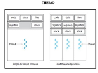
THREAD
A Threadis a Light weight process.
In a process, a thread refers to a single sequential activity
being executed.
Each thread belongs to exactly one process and no thread can
exist outside a process.
The process can be split down into so many threads.
For example, in a browser, many tabs can be viewed as
threads.
Threads are mainly used for parallel execution.
Each thread has its own TCB (Thread Control Block) like
process PCB.
Need of Thread:
Threads run in parallel improving the application
performance.
Threads can share common data so they do not need to
use inter-process communication.
It takes far less time to create a new thread in an existing
process than to create a new process.
Context switching is faster when working with threads.
It takes less time to terminate a thread than a process.
Components of Thread :
• Stack Space
• Register Set
• Program Counter
112.
TYPES OF THREAD:
There are 2 types of thread.
1. User Level Thread
2. Kernel Level Thread.
113.
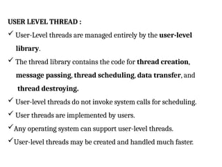
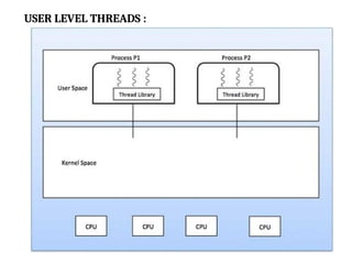
USER LEVEL THREAD:
User-Level threads are managed entirely by the user-level
library.
The thread library contains the code for thread creation,
message passing, thread scheduling, data transfer, and
thread destroying.
User-level threads do not invoke system calls for scheduling.
User threads are implemented by users.
Any operating system can support user-level threads.
User-level threads may be created and handled much faster.
114.
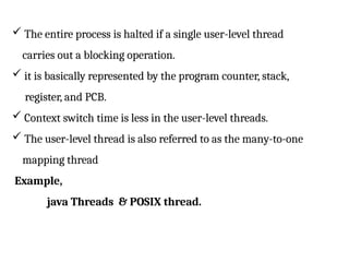
The entireprocess is halted if a single user-level thread
carries out a blocking operation.
it is basically represented by the program counter, stack,
register, and PCB.
Context switch time is less in the user-level threads.
The user-level thread is also referred to as the many-to-one
mapping thread
Example,
java Threads & POSIX thread.
115.
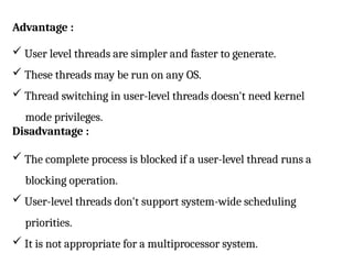
Advantage :
Userlevel threads are simpler and faster to generate.
These threads may be run on any OS.
Thread switching in user-level threads doesn't need kernel
mode privileges.
Disadvantage :
The complete process is blocked if a user-level thread runs a
blocking operation.
User-level threads don't support system-wide scheduling
priorities.
It is not appropriate for a multiprocessor system.
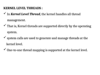
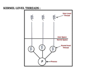
KERNEL LEVEL THREADS:
In Kernel Level Thread, the kernel handles all thread
management.
That is, Kernel threads are supported directly by the operating
system.
system calls are used to generate and manage threads at the
kernel level.
One-to-one thread mapping is supported at the kernel level.
118.
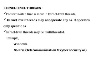
KERNEL LEVEL THREADS:
Context switch time is more in kernel-level threads.
kernel level threads may not operate any os. It operates
only specific os
kernel-level threads may be multithreaded.
Example,
Windows
Solaris (Telecommunication & cyber security os)
119.
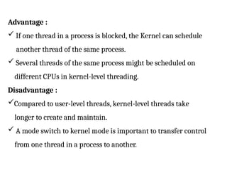
Advantage :
Ifone thread in a process is blocked, the Kernel can schedule
another thread of the same process.
Several threads of the same process might be scheduled on
different CPUs in kernel-level threading.
Disadvantage :
Compared to user-level threads, kernel-level threads take
longer to create and maintain.
A mode switch to kernel mode is important to transfer control
from one thread in a process to another.
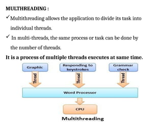
MULTHREADING :
Multithreading allowsthe application to divide its task into
individual threads.
In multi-threads, the same process or task can be done by
the number of threads.
It is a process of multiple threads executes at same time.
122.
MULTHREADING MODELS :
Some operating system provide a combined user level
thread and Kernel level thread facility.
Solaris is a good example of this combined approach.
There are 3 types of Multithreading Models
1.Many to many relationship.
2.Many to one relationship.
3.One to one relationship.
123.
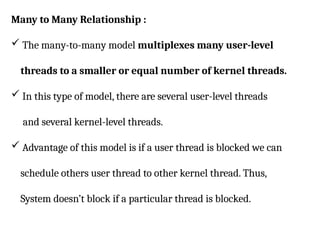
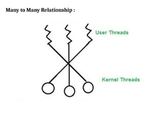
Many to ManyRelationship :
The many-to-many model multiplexes many user-level
threads to a smaller or equal number of kernel threads.
In this type of model, there are several user-level threads
and several kernel-level threads.
Advantage of this model is if a user thread is blocked we can
schedule others user thread to other kernel thread. Thus,
System doesn’t block if a particular thread is blocked.
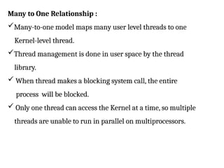
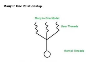
Many to OneRelationship :
Many-to-one model maps many user level threads to one
Kernel-level thread.
Thread management is done in user space by the thread
library.
When thread makes a blocking system call, the entire
process will be blocked.
Only one thread can access the Kernel at a time, so multiple
threads are unable to run in parallel on multiprocessors.
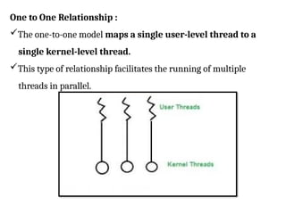
One to OneRelationship :
The one-to-one model maps a single user-level thread to a
single kernel-level thread.
This type of relationship facilitates the running of multiple
threads in parallel.
128.
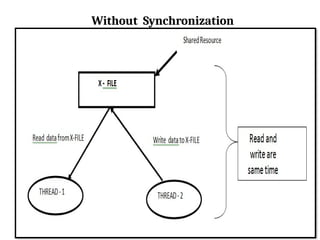
Synchronization
Process synchronization isthe concurrent execution of two or
more Process that share critical resources.
Process should be synchronized to avoid critical resource use
conflicts.
Otherwise, conflicts may arise when parallel-running Process attempt
to modify a common variable or resource at the same time.
Above situation, wemay get strange result. Or some time problem
occurred. This problem overcomes using Synchronization
techniques.
131.
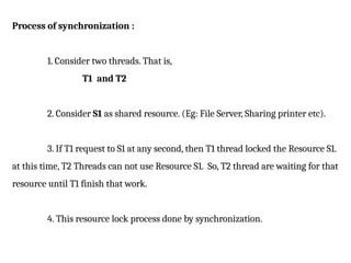
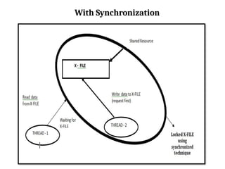
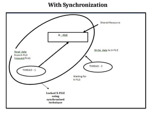
Process of synchronization:
1. Consider two threads. That is,
T1 and T2
2. Consider S1 as shared resource. (Eg: File Server, Sharing printer etc).
3. If T1 request to S1 at any second, then T1 thread locked the Resource S1.
at this time, T2 Threads can not use Resource S1. So, T2 thread are waiting for that
resource until T1 finish that work.
4. This resource lock process done by synchronization.
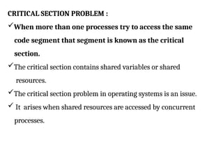
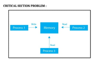
CRITICAL SECTION PROBLEM:
When more than one processes try to access the same
code segment that segment is known as the critical
section.
The critical section contains shared variables or shared
resources.
The critical section problem in operating systems is an issue.
It arises when shared resources are accessed by concurrent
processes.
135.
CRITICAL SECTION PROBLEM:
The role of the operating system here is to ensure that when
two or more processes require to access the shared
resource concurrently, only one process gets the access at a
time.
Example,
In concurrent programming, if one thread tries to
change the value of shared data at the same time as another
thread tries to read the value, the result is unpredictable. The
access to such shared variables (shared memory, shared files,
shared port, etc.) is to be synchronized.
CRITICAL SECTION PROBLEM:
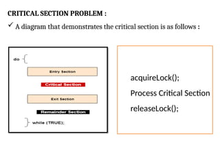
A diagram that demonstrates the critical section is as follows :
acquireLock();
Process Critical Section
releaseLock();
138.
CRITICAL SECTION PROBLEM:
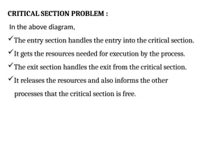
In the above diagram,
The entry section handles the entry into the critical section.
It gets the resources needed for execution by the process.
The exit section handles the exit from the critical section.
It releases the resources and also informs the other
processes that the critical section is free.
139.
SOLUTION OF CRITICALSECTION PROBLEM :
The solution to the critical section problem must satisfy the
following conditions
1. Mutual Exclusion
2. Progress
3. Bounded Waiting
140.
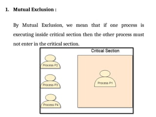
1. Mutual Exclusion:
By Mutual Exclusion, we mean that if one process is
executing inside critical section then the other process must
not enter in the critical section.
141.
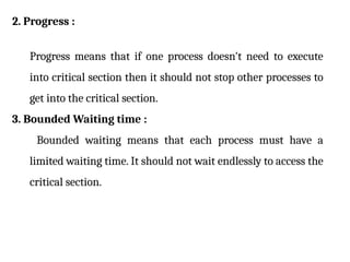
2. Progress :
Progressmeans that if one process doesn't need to execute
into critical section then it should not stop other processes to
get into the critical section.
3. Bounded Waiting time :
Bounded waiting means that each process must have a
limited waiting time. It should not wait endlessly to access the
critical section.
142.
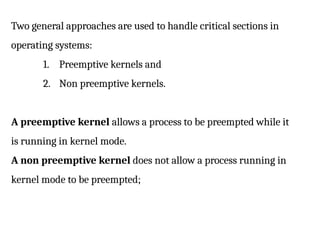
Two general approachesare used to handle critical sections in
operating systems:
1. Preemptive kernels and
2. Non preemptive kernels.
A preemptive kernel allows a process to be preempted while it
is running in kernel mode.
A non preemptive kernel does not allow a process running in
kernel mode to be preempted;
143.
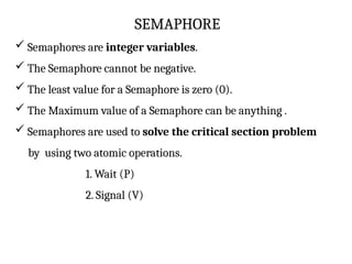
SEMAPHORE
Semaphores areinteger variables.
The Semaphore cannot be negative.
The least value for a Semaphore is zero (0).
The Maximum value of a Semaphore can be anything .
Semaphores are used to solve the critical section problem
by using two atomic operations.
1. Wait (P)
2. Signal (V)
144.
SEMAPHORE
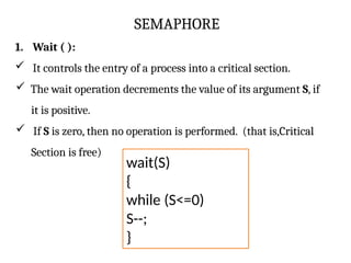
1. Wait ():
It controls the entry of a process into a critical section.
The wait operation decrements the value of its argument S, if
it is positive.
If S is zero, then no operation is performed. (that is,Critical
Section is free)
wait(S)
{
while (S<=0)
S--;
}
145.
SEMAPHORE
Here, the waitoperation has many different names. The different
names are:
1. Sleep Operation
2. Down Operation
3. Decrease Operation
4. P Function (most important alias name for wait
operation)
146.
SEMAPHORE
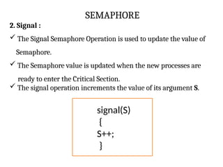
2. Signal :
The Signal Semaphore Operation is used to update the value of
Semaphore.
The Semaphore value is updated when the new processes are
ready to enter the Critical Section.
The signal operation increments the value of its argument S.
signal(S)
{
S++;
}
147.
SEMAPHORE
2. Signal :
TheSignal Operation is also known as:
1. Wake up Operation
2. Up Operation
3. Increase Operation
4. V Function (most important alias name for signal operation)
MUTEX :
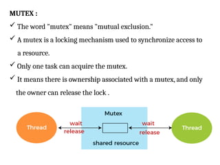
Theword "mutex" means "mutual exclusion."
A mutex is a locking mechanism used to synchronize access to
a resource.
Only one task can acquire the mutex.
It means there is ownership associated with a mutex, and only
the owner can release the lock .
150.
USE OF MUTEX:
Mutex is just simple locks obtained before entering its critical
section and then releasing it.
Since only one thread is in its critical section at any given time,
there are no race conditions, and data always remain
consistent.
151.
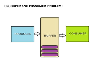
PRODUCER AND CONSUMERPROBLEM :
The Producer Consumer problem is a classical process
synchronization problem.
In this problem, there is a memory buffer of a fixed size.
Two processes access the shared buffer:
1. Producer
2. Consumer.
A producer creates new items and adds to the buffer, while a
consumer picks items from the shared buffer.
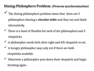
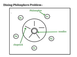
Dining-Philosphers Problem :(Processsynchronization)
The dining philosophers problem states that there are 5
philosophers sharing a circular table and they eat and think
alternatively.
There is a bowl of Noodles for each of the philosophers and 5
chopsticks.
A philosopher needs both their right and left chopstick to eat.
A hungry philosopher may only eat if there are both
chopsticks available.
Otherwise a philosopher puts down their chopstick and begin
thinking again.
READER – WRITERSPROBLEM :
The readers-writers problem relates to an object such as a
file that is shared between multiple processes.
Some of these processes are readers i.e. they only want to
read the data from the object.
some of the processes are writers i.e. they want to write into
the object.
For example :
If two readers access the object at the same time there is no
problem.
However if two writers or a reader and writer access the object
at the same time, there may be problems.
156.
READER – WRITERSPROBLEM :
To solve this situation, a writer should get exclusive access to
an object
i.e. when a writer is accessing the object, no reader or writer
may access it.
However, multiple readers can access the object at the same
time.
157.
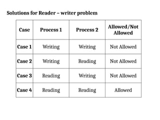
Solutions for Reader– writer problem
Case Process 1 Process 2
Allowed/Not
Allowed
Case 1 Writing Writing Not Allowed
Case 2 Writing Reading Not Allowed
Case 3 Reading Writing Not Allowed
Case 4 Reading Reading Allowed