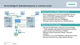
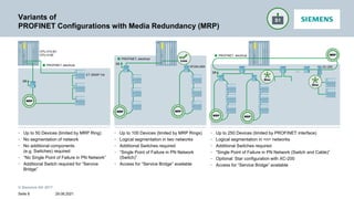
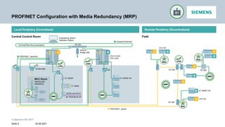
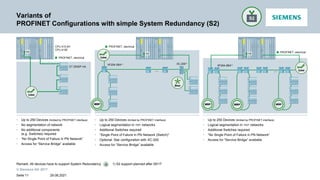
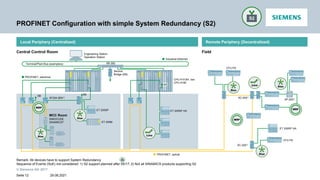
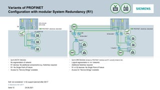
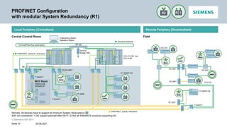
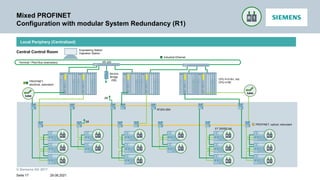
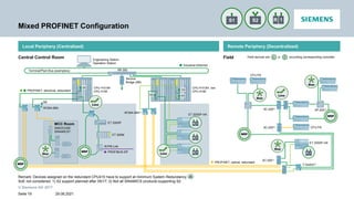
PROFINET@PA
Network topologies
Restricted © Siemens AG 2017
© Siemens AG 2017
Motivation
29.08.2021
• High flexibility in the fieldbus architecture with PROFINET
• Support in the planning phase
• Modular standard solutions
• Tested configurations
Seite 2
© Siemens AG 2017
Agenda
PROFINET Configuration with modular System Redundancy (R1)
Simple PROFINET Configuration (S1)
PROFINET Configuration with simple System Redundancy (S2)
PROFINET Basics
Mixed Configuration
29.08.2021
Seite 3
© Siemens AG 2017
PROFINET Basics
29.08.2021
Description
Symbol
CPU 410-4H
Single Device
CPU 410-4H, red.
Single Device (S2)
CPU 410-4H, red.
Single Device (S2)
Red. Device (R1)
Y-Switch
Single Device
CPU 410-5H
1 Per CPU410-5H PROFINET interface; 2 Release of up to 250 Devices planned
Ring Redundancy
• Combinable with System Redundancy
• Max 50 Devices; re-configuration time up to 200ms
• Note: All Devices in the Ring have to support MRP
PROFINET Configuration with modular
System Redundancy (R1)
• Up to 250 Devices total with Single PROFINET Interface1
including the capability of up to 64 of those devices having a
redundant interface (R1) 2
• Note: All Devices have to support R1 or S2 by using Y-Switch
Simple PROFINET Configuration
• Up to 250 Devices with Single PROFINET Interface1
PN Configuration with simple System Redundancy (S2)
• Up to 250 Devices with Single PROFINET Interface1
• Note: All Devices have to support S2
Seite 4
© Siemens AG 2017
Service Bridge for dedicated temporary or continues access
Service access to fieldbus required for
• Manual addressing and naming of PROFINET devices
• Scan of PROFINET topology with STEP 7 Topology
Editor (e.g. target/actual comparison)
• Use of commission tools (e.g. PRONETA)
• Extended network diagnostic (e.g. SINEMA Server)
Features of Service Bridge
• Standard XC-200 Switch configured as Service Bridge
• Easy installation with Manual and prepared config files
• Layer 2 access from Plant Bus to Fieldbus
• Maintains network separation between redundant
networks
• Connection of up to 23x PROFINET network with XC 224
• Security mechanisms (e.g. MAC-address filtering)
XC-200
Plant Bus - Industrial Ethernet
CPU410-5H
ET 200SP HA
CFU PA
Y-Switch
Fieldbus - PROFINET
MS
Service
Bridge
Further
PN Networks
Layer 2/Layer 3
Dedicated
temporary access
ES/OS
Service
Bridge
Further
PN Networks
Dedicated
continues access
e.g. SINEMA
Server
Layer 2/Layer 3
Page 5 29.08.2021
© Siemens AG 2017
PROFINET Switches
Y-Switch - SCALANCE XF 204-2BA DNA
PRELIMINARY (Target Release Date âž” Q3.2017)
CFU PA
PROFIBUS-PA Field
Devices
ET 200M
Y-Switch
(XF204-2BA DNA)
4-wire Field
Devices
(external powered)
XF204-2BA
XP-200
Integrated drives
SIMOCODE
SINAMICS
XC-200
ET 200SP
CPU 410-5H
Redundant
Automation Systems
• Two isolated ports to connect Y-Switch on redundant
network (R1)
• Two switched ports to connect S2-Devices
• MRP supported
Adaptable Bus Adapter for each Interface
Y-Switch is transparent
• No configuration required
• No limitations in quantity
Installation up to Ex-Zone 2
• -40° C to +70° C
• Conformal coating
• NE21 conformal
Remark: PROFINET standard determines, devices used in Process Automation have to support S2 System Redundancy (mandatory for PROFINET certification according to CC-B (PA))
Connect devices with a singular PROFINET interface, which support S2
System Redundancy, on a redundant PROFINET network, while network
separation of redundant network is maintained
29.08.2021
Seite 6
© Siemens AG 2017
Agenda
29.08.2021
Seite 7
PROFINET Configuration with modular System Redundancy (R1)
Simple PROFINET Configuration (S1)
PROFINET Configuration with simple System Redundancy (S2)
PROFINET Basics
Mixed Configuration
© Siemens AG 2017
Variants of
PROFINET Configurations with Media Redundancy (MRP)
29.08.2021
Seite 8
CPU 410-5H
CPU 410E
PROFINET, electrical
ET 200SP HA
SB
• Up to 50 Devices (limited by MRP Ring)
• No segmentation of network
• No additional components
(e.g. Switches) required
• “No Single Point of Failure in PN Network”
• Additional Switch required for “Service
Bridge”
PROFINET, electrical
SB
XF204-2BA
PROFINET, electrical
…
XC-200
SB
• Up to 100 Devices (limited by MRP Rings)
• Logical segmentation in two networks
• Additional Switches required
• “Single Point of Failure in PN Network
(Switch)”
• Access for “Service Bridge” available
• Up to 250 Devices (limited by PROFINET interface)
• Logical segmentation in <n> networks
• Additional Switches required
• “Single Point of Failure in PN Network (Switch and Cable)”
• Optional: Star configuration with XC-200
• Access for “Service Bridge” available
© Siemens AG 2017
PROFINET Configuration with Media Redundancy (MRP)
29.08.2021
Seite 9
SB
Local Periphery (Centralized) Remote Periphery (Decentralized)
Central Control Room Field
PROFINET, electrical
PROFIBUS-DP
IE/PB-Link PN IO
ET 200M
ET 200SP
CPU 410-5H
CPU 410E
Industrial Ethernet
Terminal/Plant Bus (exemplary)
Engineering Station
Operation Station
XR-300
Service
Bridge (SB)
MCC Room
SIMOCODE
SINAMICS
ET 200SP HA
CFU PA
XC-200 XP-200
CFU PA
SB
XF204-2BA
PROFINET, optical
SB
ET 200SP HA
A B B
A A
B
A
B
A
A
B
XC-200
© Siemens AG 2017
Agenda
29.08.2021
Seite 10
PROFINET Configuration with modular System Redundancy (R1)
Simple PROFINET Configuration (S1)
PROFINET Configuration with simple System Redundancy (S2)
PROFINET Basics
Mixed Configuration
© Siemens AG 2017
Variants of
PROFINET Configurations with simple System Redundancy (S2)
29.08.2021
SB
SB
ET 200SP HA
PROFINET, electrical
• Up to 250 Devices (limited by PROFINET interface)
• No segmentation of network
• No additional components
(e.g. Switches) required
• “No Single Point of Failure in PN Network”
• Access for “Service Bridge” available
• Up to 250 Devices (limited by PROFINET interface)
• Logical segmentation in <n> networks
• Additional Switches required
• “Single Point of Failure in PN Network (Switch)”
• Optional: Star configuration with XC-200
• Access for “Service Bridge” available
XF204-2BA1)
…
PROFINET, electrical
SB
PROFINET, electrical
XF204-2BA1) XC-2001)
…
• Up to 250 Devices (limited by PROFINET interface)
• Logical segmentation in <n> networks
• Additional Switches required
• “No Single Point of Failure in PN Network”
• Access for “Service Bridge” available
CPU 410-5H
CPU 410E
Remark: All devices have to support System Redundancy 1) S2 support planned after 05/17
Seite 11
© Siemens AG 2017
PROFINET Configuration with simple System Redundancy (S2)
29.08.2021
Seite 12
Local Periphery (Centralized) Remote Periphery (Decentralized)
Central Control Room Field
Remark: All devices have to support System Redundancy
Sequence of Events (SoE) not considered: 1) S2 support planned after 05/17; 2) Not all SINAMICS products supporting S2
Industrial Ethernet
ET 200SP HA
PROFINET, electrical
Service
Bridge (SB)
Terminal/Plant Bus (exemplary)
Engineering Station
Operation Station
XR-300
SB
CFU PA
XF204-2BA1)
MCC Room
CPU 410-5H, red.
CPU 410E
SIMOCODE
SINAMICS2)
Y
XC-2001)
XP-2001)
SB
ET 200M
ET 200SP
SB
CFU PA
PROFINET, optical
ET 200SP HA
XC-2001)
© Siemens AG 2017
PROFINET Configuration with simple System Redundancy (S2)
Industrial Ethernet
PROFINET,
electrical
Service
Bridge
(SB)
XR-300
Terminal / Plant Bus (exemplary)
Engineering Station
Operation Station
CPU 410-5H, red.
CPU 410E
SB
Local Periphery (Centralized)
Central Control Room
XF204-2BA
XC 200
29.08.2021
Seite 13
© Siemens AG 2017
Agenda
29.08.2021
Seite 14
PROFINET Configuration with modular System Redundancy (R1)
Simple PROFINET Configuration (S1)
PROFINET Configuration with simple System Redundancy (S2)
PROFINET Basics
Mixed Configuration
© Siemens AG 2017
Variants of PROFINET
Configuration with modular System Redundancy (R1)
29.08.2021
Seite 15
SB
SB
• Up to 64 R1-Devices
• No segmentation of network
• R1 devices: No additional components (e.g. Switches) required
• R1: No Single Point of Failure
• Access for “Service Bridge” available
CPU 410-5H
CPU 410E
ET 200SP HA
PROFINET, electrical, redundant
• Up to 250 Devices (limited by PROFINET interface and R1 currently limited to 64)
• Logical segmentation in <n> networks
• Additional Switches required
• R1 or S2-devices: No Single Point of Failure
• Access for “Service Bridge” available
SB
PROFINET, electrical, redundant
SB
Y Y-Switch1)
XF204-2BA1)
Y-Switch1)
XF204-2BA1)
SoE not considered: 1) S2 support planned after 05/17
© Siemens AG 2017
PROFINET Configuration
with modular System Redundancy (R1)
29.08.2021
Seite 16
PROFINET, optical, redundant
Local Periphery (Centralized) Remote Periphery (Decentralized)
Central Control Room Field
Remark: All devices have to support at minimum System Redundancy
SoE not considered: 1) S2 support planned after 05/17; 2) Not all SINAMICS products supporting S2;
Industrial Ethernet
ET 200SP HA
PROFINET, electrical, redundant
Service
Bridge (SB)
Terminal/Plant Bus (exemplary)
Engineering Station
Operation Station
XR-300
SB
CFU PA
CFU PA
ET 200M
Y-Switch1)
XF204-2BA1)
Y
SB
MCC Room
Y
CPU 410-5H, red.
CPU 410E
SIMOCODE
SINAMICS2)
Y-Switch1)
XC-2001)
XP-2001)
SB
SB
SB
SB
Y
Y
XC-2001)
XC-2001)
ET 200SP HA
Y-Switch1)
© Siemens AG 2017
Mixed PROFINET
Configuration with modular System Redundancy (R1)
Industrial Ethernet
ET 200SP HA
PROFINET, optical, redundant
PROFINET,
electrical, redundant
XF204-2BA
Service
Bridge
(SB)
XR-300
Terminal / Plant Bus (exemplary)
Engineering Station
Operation Station
SB
CPU 410-5H, red.
CPU 410E
SB
Local Periphery (Centralized)
Central Control Room
29.08.2021
Seite 17
© Siemens AG 2017
Agenda
29.08.2021
Seite 18
PROFINET Configuration with modular System Redundancy (R1)
Single PROFINET Configuration (S1)
PROFINET Configuration with simple System Redundancy (S2)
PROFINET Basics
Mixed Configuration
© Siemens AG 2017
Mixed PROFINET Configuration
29.08.2021
Seite 19
PROFINET, optical, redundant
CPU 410-5H
CPU 410E
Local Periphery (Centralized) Remote Periphery (Decentralized)
Central Control Room Field
Remark: Devices assigned on the redundant CPU410 have to support at minimum System Redundancy
SoE not considered: 1) S2 support planned after 05/17; 2) Not all SINAMICS products supporting S2
Industrial Ethernet
PROFINET, electrical, redundant
Service
Bridge (SB)
Terminal/Plant Bus (exemplary)
Engineering Station
Operation Station
XR-300
SB
SB
ET 200SP HA
CFU PA
CFU PA
CPU 410-5H, red.
CPU 410E
Y-Switch1)
XC-2001)
XP-2001)
SB
SB
PROFIBUS-DP
IE/PB-Link
ET 200M
MCC Room
SIMOCODE
SINAMICS2)
SB
XF204-2BA
XF204-2BA1)
Field devices are or according corresponding controller
S2
S1
ET 200SP HA
ET 200SP
XC-2001)
XC-2001)
© Siemens AG 2017
Summary
29.08.2021
• Tested PROFINET configurations
• Best Practice solutions
• Modular standard solutions
Seite 20
© Siemens AG 2017
Thank you for your attention!
Manfred Schaffrinna
PD PA AE SUP SPS 1
Ă–stliche RheinbrĂĽckenstr. 50
76187 Karlsruhe
E-Mail: pcs7.industry@siemens.com
29.08.2021
siemens.com
Seite 21

Profinet PA network topologies ggfffdgfg

  • 1.
  • 2.
    © Siemens AG2017 Motivation 29.08.2021 • High flexibility in the fieldbus architecture with PROFINET • Support in the planning phase • Modular standard solutions • Tested configurations Seite 2
  • 3.
    © Siemens AG2017 Agenda PROFINET Configuration with modular System Redundancy (R1) Simple PROFINET Configuration (S1) PROFINET Configuration with simple System Redundancy (S2) PROFINET Basics Mixed Configuration 29.08.2021 Seite 3
  • 4.
    © Siemens AG2017 PROFINET Basics 29.08.2021 Description Symbol CPU 410-4H Single Device CPU 410-4H, red. Single Device (S2) CPU 410-4H, red. Single Device (S2) Red. Device (R1) Y-Switch Single Device CPU 410-5H 1 Per CPU410-5H PROFINET interface; 2 Release of up to 250 Devices planned Ring Redundancy • Combinable with System Redundancy • Max 50 Devices; re-configuration time up to 200ms • Note: All Devices in the Ring have to support MRP PROFINET Configuration with modular System Redundancy (R1) • Up to 250 Devices total with Single PROFINET Interface1 including the capability of up to 64 of those devices having a redundant interface (R1) 2 • Note: All Devices have to support R1 or S2 by using Y-Switch Simple PROFINET Configuration • Up to 250 Devices with Single PROFINET Interface1 PN Configuration with simple System Redundancy (S2) • Up to 250 Devices with Single PROFINET Interface1 • Note: All Devices have to support S2 Seite 4
  • 5.
    © Siemens AG2017 Service Bridge for dedicated temporary or continues access Service access to fieldbus required for • Manual addressing and naming of PROFINET devices • Scan of PROFINET topology with STEP 7 Topology Editor (e.g. target/actual comparison) • Use of commission tools (e.g. PRONETA) • Extended network diagnostic (e.g. SINEMA Server) Features of Service Bridge • Standard XC-200 Switch configured as Service Bridge • Easy installation with Manual and prepared config files • Layer 2 access from Plant Bus to Fieldbus • Maintains network separation between redundant networks • Connection of up to 23x PROFINET network with XC 224 • Security mechanisms (e.g. MAC-address filtering) XC-200 Plant Bus - Industrial Ethernet CPU410-5H ET 200SP HA CFU PA Y-Switch Fieldbus - PROFINET MS Service Bridge Further PN Networks Layer 2/Layer 3 Dedicated temporary access ES/OS Service Bridge Further PN Networks Dedicated continues access e.g. SINEMA Server Layer 2/Layer 3 Page 5 29.08.2021
  • 6.
    © Siemens AG2017 PROFINET Switches Y-Switch - SCALANCE XF 204-2BA DNA PRELIMINARY (Target Release Date ➔ Q3.2017) CFU PA PROFIBUS-PA Field Devices ET 200M Y-Switch (XF204-2BA DNA) 4-wire Field Devices (external powered) XF204-2BA XP-200 Integrated drives SIMOCODE SINAMICS XC-200 ET 200SP CPU 410-5H Redundant Automation Systems • Two isolated ports to connect Y-Switch on redundant network (R1) • Two switched ports to connect S2-Devices • MRP supported Adaptable Bus Adapter for each Interface Y-Switch is transparent • No configuration required • No limitations in quantity Installation up to Ex-Zone 2 • -40° C to +70° C • Conformal coating • NE21 conformal Remark: PROFINET standard determines, devices used in Process Automation have to support S2 System Redundancy (mandatory for PROFINET certification according to CC-B (PA)) Connect devices with a singular PROFINET interface, which support S2 System Redundancy, on a redundant PROFINET network, while network separation of redundant network is maintained 29.08.2021 Seite 6
  • 7.
    © Siemens AG2017 Agenda 29.08.2021 Seite 7 PROFINET Configuration with modular System Redundancy (R1) Simple PROFINET Configuration (S1) PROFINET Configuration with simple System Redundancy (S2) PROFINET Basics Mixed Configuration
  • 8.
    © Siemens AG2017 Variants of PROFINET Configurations with Media Redundancy (MRP) 29.08.2021 Seite 8 CPU 410-5H CPU 410E PROFINET, electrical ET 200SP HA SB • Up to 50 Devices (limited by MRP Ring) • No segmentation of network • No additional components (e.g. Switches) required • “No Single Point of Failure in PN Network” • Additional Switch required for “Service Bridge” PROFINET, electrical SB XF204-2BA PROFINET, electrical … XC-200 SB • Up to 100 Devices (limited by MRP Rings) • Logical segmentation in two networks • Additional Switches required • “Single Point of Failure in PN Network (Switch)” • Access for “Service Bridge” available • Up to 250 Devices (limited by PROFINET interface) • Logical segmentation in <n> networks • Additional Switches required • “Single Point of Failure in PN Network (Switch and Cable)” • Optional: Star configuration with XC-200 • Access for “Service Bridge” available
  • 9.
    © Siemens AG2017 PROFINET Configuration with Media Redundancy (MRP) 29.08.2021 Seite 9 SB Local Periphery (Centralized) Remote Periphery (Decentralized) Central Control Room Field PROFINET, electrical PROFIBUS-DP IE/PB-Link PN IO ET 200M ET 200SP CPU 410-5H CPU 410E Industrial Ethernet Terminal/Plant Bus (exemplary) Engineering Station Operation Station XR-300 Service Bridge (SB) MCC Room SIMOCODE SINAMICS ET 200SP HA CFU PA XC-200 XP-200 CFU PA SB XF204-2BA PROFINET, optical SB ET 200SP HA A B B A A B A B A A B XC-200
  • 10.
    © Siemens AG2017 Agenda 29.08.2021 Seite 10 PROFINET Configuration with modular System Redundancy (R1) Simple PROFINET Configuration (S1) PROFINET Configuration with simple System Redundancy (S2) PROFINET Basics Mixed Configuration
  • 11.
    © Siemens AG2017 Variants of PROFINET Configurations with simple System Redundancy (S2) 29.08.2021 SB SB ET 200SP HA PROFINET, electrical • Up to 250 Devices (limited by PROFINET interface) • No segmentation of network • No additional components (e.g. Switches) required • “No Single Point of Failure in PN Network” • Access for “Service Bridge” available • Up to 250 Devices (limited by PROFINET interface) • Logical segmentation in <n> networks • Additional Switches required • “Single Point of Failure in PN Network (Switch)” • Optional: Star configuration with XC-200 • Access for “Service Bridge” available XF204-2BA1) … PROFINET, electrical SB PROFINET, electrical XF204-2BA1) XC-2001) … • Up to 250 Devices (limited by PROFINET interface) • Logical segmentation in <n> networks • Additional Switches required • “No Single Point of Failure in PN Network” • Access for “Service Bridge” available CPU 410-5H CPU 410E Remark: All devices have to support System Redundancy 1) S2 support planned after 05/17 Seite 11
  • 12.
    © Siemens AG2017 PROFINET Configuration with simple System Redundancy (S2) 29.08.2021 Seite 12 Local Periphery (Centralized) Remote Periphery (Decentralized) Central Control Room Field Remark: All devices have to support System Redundancy Sequence of Events (SoE) not considered: 1) S2 support planned after 05/17; 2) Not all SINAMICS products supporting S2 Industrial Ethernet ET 200SP HA PROFINET, electrical Service Bridge (SB) Terminal/Plant Bus (exemplary) Engineering Station Operation Station XR-300 SB CFU PA XF204-2BA1) MCC Room CPU 410-5H, red. CPU 410E SIMOCODE SINAMICS2) Y XC-2001) XP-2001) SB ET 200M ET 200SP SB CFU PA PROFINET, optical ET 200SP HA XC-2001)
  • 13.
    © Siemens AG2017 PROFINET Configuration with simple System Redundancy (S2) Industrial Ethernet PROFINET, electrical Service Bridge (SB) XR-300 Terminal / Plant Bus (exemplary) Engineering Station Operation Station CPU 410-5H, red. CPU 410E SB Local Periphery (Centralized) Central Control Room XF204-2BA XC 200 29.08.2021 Seite 13
  • 14.
    © Siemens AG2017 Agenda 29.08.2021 Seite 14 PROFINET Configuration with modular System Redundancy (R1) Simple PROFINET Configuration (S1) PROFINET Configuration with simple System Redundancy (S2) PROFINET Basics Mixed Configuration
  • 15.
    © Siemens AG2017 Variants of PROFINET Configuration with modular System Redundancy (R1) 29.08.2021 Seite 15 SB SB • Up to 64 R1-Devices • No segmentation of network • R1 devices: No additional components (e.g. Switches) required • R1: No Single Point of Failure • Access for “Service Bridge” available CPU 410-5H CPU 410E ET 200SP HA PROFINET, electrical, redundant • Up to 250 Devices (limited by PROFINET interface and R1 currently limited to 64) • Logical segmentation in <n> networks • Additional Switches required • R1 or S2-devices: No Single Point of Failure • Access for “Service Bridge” available SB PROFINET, electrical, redundant SB Y Y-Switch1) XF204-2BA1) Y-Switch1) XF204-2BA1) SoE not considered: 1) S2 support planned after 05/17
  • 16.
    © Siemens AG2017 PROFINET Configuration with modular System Redundancy (R1) 29.08.2021 Seite 16 PROFINET, optical, redundant Local Periphery (Centralized) Remote Periphery (Decentralized) Central Control Room Field Remark: All devices have to support at minimum System Redundancy SoE not considered: 1) S2 support planned after 05/17; 2) Not all SINAMICS products supporting S2; Industrial Ethernet ET 200SP HA PROFINET, electrical, redundant Service Bridge (SB) Terminal/Plant Bus (exemplary) Engineering Station Operation Station XR-300 SB CFU PA CFU PA ET 200M Y-Switch1) XF204-2BA1) Y SB MCC Room Y CPU 410-5H, red. CPU 410E SIMOCODE SINAMICS2) Y-Switch1) XC-2001) XP-2001) SB SB SB SB Y Y XC-2001) XC-2001) ET 200SP HA Y-Switch1)
  • 17.
    © Siemens AG2017 Mixed PROFINET Configuration with modular System Redundancy (R1) Industrial Ethernet ET 200SP HA PROFINET, optical, redundant PROFINET, electrical, redundant XF204-2BA Service Bridge (SB) XR-300 Terminal / Plant Bus (exemplary) Engineering Station Operation Station SB CPU 410-5H, red. CPU 410E SB Local Periphery (Centralized) Central Control Room 29.08.2021 Seite 17
  • 18.
    © Siemens AG2017 Agenda 29.08.2021 Seite 18 PROFINET Configuration with modular System Redundancy (R1) Single PROFINET Configuration (S1) PROFINET Configuration with simple System Redundancy (S2) PROFINET Basics Mixed Configuration
  • 19.
    © Siemens AG2017 Mixed PROFINET Configuration 29.08.2021 Seite 19 PROFINET, optical, redundant CPU 410-5H CPU 410E Local Periphery (Centralized) Remote Periphery (Decentralized) Central Control Room Field Remark: Devices assigned on the redundant CPU410 have to support at minimum System Redundancy SoE not considered: 1) S2 support planned after 05/17; 2) Not all SINAMICS products supporting S2 Industrial Ethernet PROFINET, electrical, redundant Service Bridge (SB) Terminal/Plant Bus (exemplary) Engineering Station Operation Station XR-300 SB SB ET 200SP HA CFU PA CFU PA CPU 410-5H, red. CPU 410E Y-Switch1) XC-2001) XP-2001) SB SB PROFIBUS-DP IE/PB-Link ET 200M MCC Room SIMOCODE SINAMICS2) SB XF204-2BA XF204-2BA1) Field devices are or according corresponding controller S2 S1 ET 200SP HA ET 200SP XC-2001) XC-2001)
  • 20.
    © Siemens AG2017 Summary 29.08.2021 • Tested PROFINET configurations • Best Practice solutions • Modular standard solutions Seite 20
  • 21.
    © Siemens AG2017 Thank you for your attention! Manfred Schaffrinna PD PA AE SUP SPS 1 Östliche Rheinbrückenstr. 50 76187 Karlsruhe E-Mail: pcs7.industry@siemens.com 29.08.2021 siemens.com Seite 21