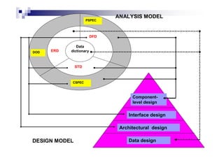
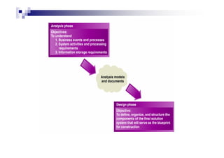
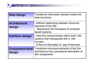
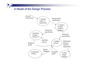
This document discusses key concepts and principles of software design. It explains that software design transforms analysis models into a design model through activities like architectural design, interface design, data design, and component-level design. Some key design concepts discussed include abstraction, refinement, modularity, architecture, procedures, and information hiding. The document also covers principles of effective modular design such as high cohesion and low coupling between modules. Different types of cohesion and coupling are defined. Overall, the document provides an overview of the software design process and some fundamental concepts involved.


![Design Concepts…cont
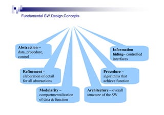
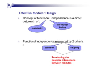
3. Modularity
• system is decomposed into a number of modules
• software architecture and design patterns embody modularity
• 5 criteria to evaluate a design method with respect to its ability to
define effective modular system [meyer,88]
i. modular decomposability
- provides a systematic approach for decomposing the problem
into subproblems
ii. modular composability
- enables existing(reusable) design components to be
assembled into a new system
o](https://image.slidesharecdn.com/refup-221120020701-7ba46e7e/85/rEFUP-pdf-16-320.jpg)
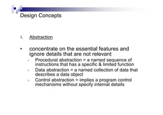
![Design Concepts…cont
5 criteria to evaluate a design method with respect to its
ability to define effective modular system [meyer,88]
iii. modular understandability
- module can be understood as a standalone unit (
no need to refer to other modules)
iv. modular continuity
- small changes to the system requirements result
in changes to individual modules
v. modular protection
- unexpected condition occurs within a module & its
effects are constrained within that module](https://image.slidesharecdn.com/refup-221120020701-7ba46e7e/85/rEFUP-pdf-17-320.jpg)
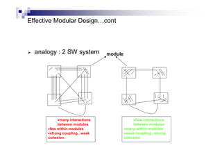
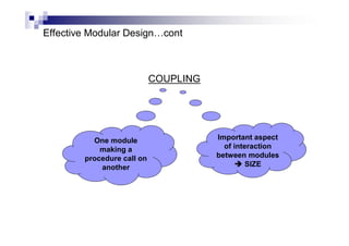
![Effective Modular Design…cont
A piece of SW divided into modules :
There is a minimum interactions between modules
[low coupling] AND
High degree of interaction within a module
[ high cohesion ]
achieved
Individual module can be :
DESIGNED, CODED,
TESTED OR CHANGED](https://image.slidesharecdn.com/refup-221120020701-7ba46e7e/85/rEFUP-pdf-27-320.jpg)
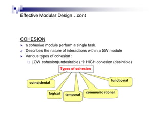
![Coupling
If modules share common data, it should be minimized
Few parameters should be passed between modules in
procedure calls [recommended 2 – 4 parameters ]
Types of coupling, from strongly coupled (least desirable )
weakly coupled (most desirable) :
1. Content coupling
2. Common coupling
3. External coupling
4. Control coupling
5. Stamp coupling
6. Data coupling](https://image.slidesharecdn.com/refup-221120020701-7ba46e7e/85/rEFUP-pdf-34-320.jpg)
![Types of coupling [pressman]
a
c
b
d
h
g
f
e
k
j
i
Data
structure
Data
(Var)
Control
flag
No direct
coupling
Global data
area](https://image.slidesharecdn.com/refup-221120020701-7ba46e7e/85/rEFUP-pdf-41-320.jpg)
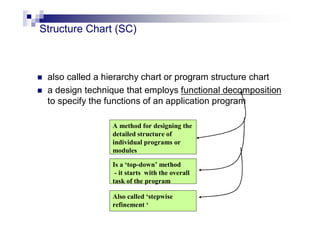
![A few guidelines to use structure charts effectively
:
Level 1 of a SC may have only 1 module ( the
boss module, executive module or main module )
Each module should perform only 1 function
Modules at each level should be arranged in
sequential order (Left – Right). [ exception to :
modules that represent alternative functions
selected by higher-level module ]
Selection symbol used to indicate that not all
modules at the next lower level will be performed](https://image.slidesharecdn.com/refup-221120020701-7ba46e7e/85/rEFUP-pdf-44-320.jpg)