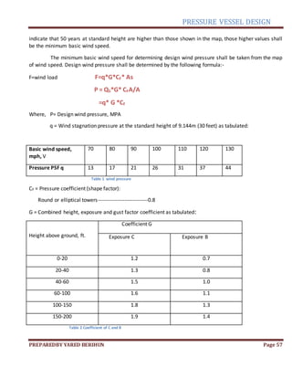
This document outlines the design of a pressure vessel with an acidic solution medium. It discusses key considerations for the design such as material selection, ventilation systems, and secondary containment liners to protect against corrosion. The document also provides specifications for the pressure vessel including an internal pressure of 14 MPa, volume of 3.4 cubic meters, and vertical position. It notes the vessel will have leg supports and connecting pipes. The length and diameter of the vessel will be determined based on its specified volume of 3.4 cubic meters.


![PRESSURE VESSEL DESIGN
PREPAREDBY YARED BERIHUN Page 13
CHAPTER TW0
CHAPTER 2
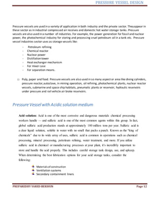
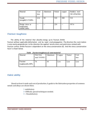
2.1. Designing procedure
Determine the length and diameter of the vessel
Designspecification
1. Main parameter
1.Medium Acid solution
ii. Inner service pressure: [MPa] 14
iii. Nominal Volume: [m3] 3.4
iv. Service temperature: [℃] 405
V .Position VERICAL
2. Supporting Element
Supporting element LEG
3. Connecting Pipe
a. Two longitudinal, one lateral, with
Nominal Diameter, [mm] 70
b. One Bottom discharge pipe, if necessary with flange
Nominal Diameter, [mm] 30](https://image.slidesharecdn.com/yaredberihunidno11004374-220601192505-5c45b677/85/Pressure-vessel-project-docx-13-320.jpg)


![PRESSURE VESSEL DESIGN
PREPAREDBY YARED BERIHUN Page 29
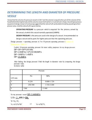
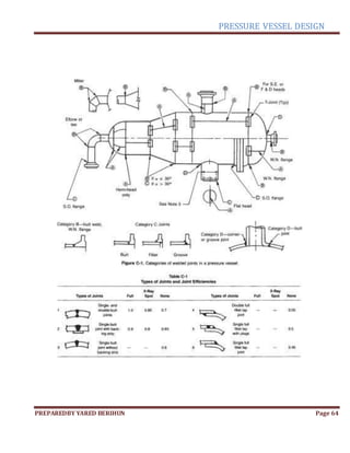
Do=2*0.5271m
Do=1.0542m (ans.)
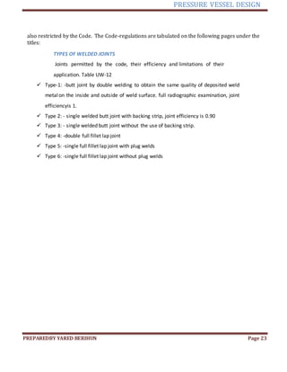
Design of HEAD
My pressure vessel is vertical with hemispherical head in shape and 1.76MPa internal
design pressure is applied on it and it’s thickness is given blow
According on the two theory
1) thin-shell theory
δ= (PR)/ (2t)
2) ‘’exact’’ theory
δ= [PRi
3/Ro
3 -Ri
3 ] [1+Ro
3 /2Ri
3 ]
Given values
Ri=0.4571m
Ro=0.5271m
P=14MPa
t=70mm=0.07m
E=1
C.A=2mm=0.002m
thin-shell theory
δ= (PRi)/ (2t)
δ= (14MPa*0.4571)/ (2*0.07m)
δ=45.71MPa …………………….. (ans.)
‘’exact’’ theory
δ= [PRi
3/ (R0
3-Ri
3)] [1+R0
3/2Ri
3]
δ= [(14MPa*(0.4571) 3)/ (0.52713-0.45713) m3] *[1 + (0.52713/2*0.45713)]
δ=46.372MPa …………………….(ans.)
Therefore let's find the head thickness and take the largest value for δ=46.372MPa.](https://image.slidesharecdn.com/yaredberihunidno11004374-220601192505-5c45b677/85/Pressure-vessel-project-docx-29-320.jpg)

![PRESSURE VESSEL DESIGN
PREPAREDBY YARED BERIHUN Page 32
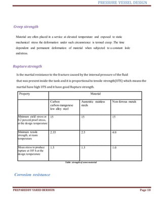
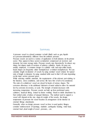
t=PRi/ (2SE-0.2P)
Where
P=internal design pressure
E=joint efficiency
R0= external radius
Ri=internal radius
S= allowable shear
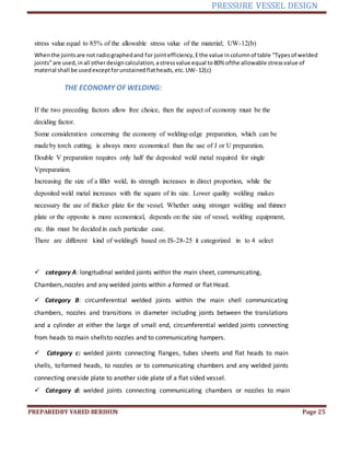
Ellipsoidalhead
Most standard ellipsoidal heads are manufactured with a major and minor axis ratio of 2 : 1. For this ratio,
the following equation can be used to calculate the minimum thickness required:
The design thickness of elliptical head is given by
t=PDK/ (2SE-0.2P)
where D-shell diameter
K-stress intensity factor
K= [1/6 + (a/b)2]
a and b semi-major, semi-minor axes of ellipse
P=internal design pressure
E=joint efficiency
S= allowable shear
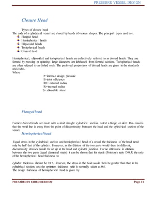
Torispherical head
There are two junctions in a torispherical end closure: that between the cylindrical section and the head,
and that at the junction of the crown and the knuckle radii. The bending and shear stresses caused by the
differential dilation that will occur at these points must be taken into account in the design of the heads. One
approach taken is to use the basic equation for a hemisphere and to introduce a stress concentration, or
shape, factor to allow for the increased stress due to the discontinuity. The stress concentration factor is a
function of the knuckle and crown radii.
The design thickness of Tori spherical head is given by
t=PLM/ (2SE-0.2P)
where L-spherical cross radius
M=1/4[1/3 + (L/r) 1/2]
M-shear intensity factor
r-knuckle radiuses
Conical head
Conical sections (reducers) are used to make a gradual reduction in diameter from one cylindrical section
to another of smaller diameter. Conical ends are used to facilitate the smooth flow and removal of solids
from process equipment; such as hoppers, spray-dryers and crystallisers.](https://image.slidesharecdn.com/yaredberihunidno11004374-220601192505-5c45b677/85/Pressure-vessel-project-docx-32-320.jpg)


![PRESSURE VESSEL DESIGN
PREPAREDBY YARED BERIHUN Page 38
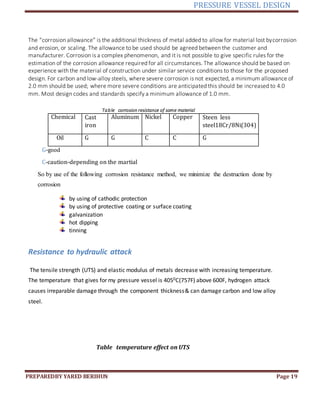
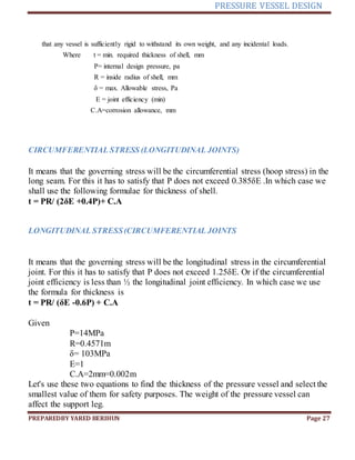
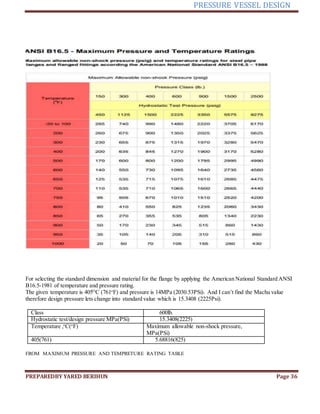
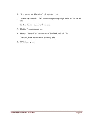
14 23.75 2.75 16.25 17.00 20-1.50 20.75 6.50 14.00 3.69 14.14 0.50 5.00 14.18 14.19 2.88
16 27.00 3.00 18.50 19.50 20-1.62 23.75 7.00 16.00 4.19 16.16 0.50 5.50 16.19 18.19 3.06
18 29.25 3.25 21.00 21.50 20-1.75 25.75 7.25 18.00 4.62 18.18 0.50 6.00 18.20 18.10 3.12
20 32.00 3.50 23.00 24.00 24-1.75 28.50 7.50 20.00 5.00 20.20 0.50 6.50 20.25 20.19 3.25
22 34.25 3.75 25.25 26.25 24-1.75 30.63 7.75 22.00 5.25 22.22 0.50 6.88 22.25 -- --
24 37.00 4.00 27.25 28.25 24-2.00 33.00 8.00 24.00 5.50 24.25 0.50 7.25 24.25 24.19 3.62
Nominal
pipe size(m
m)
Diameter of
the bore(mm)
[A]
Length
through the
hub(mm
)[C]
Diameter of
the hubat
the point of
welding[E]
Diameter of
the hubatthe
base(mm)[G]
Outside
diameterof
flange(m
m)[H]
Thickness of
flange(mm
)[J]
Outside
diamete r of
raiseface(m
m)[K]
Bolt
ing
70mm(2
…
8
in)
25mm(1in) 81.25mm
(3.25in)
87.5mm(3.5in
)
115.5mm(4.62in
)
206.25mm(8.25i
n)
31.25mm(1.25in) 125mm
(5in)
M16
30mm(1.2IN
)
25(1in) 65.5mm
(2.62in)
41.5mm(1.66i
n)
62.5mm(2.5in) 131.25mm(5.25i
n)
20.25mm(0.81in) 62.5mm(2.5in
)
M12
25mm(1
in)
25(in) 97mm(2.44in) 33mm(
1.32in)
53mm(
2.12in)
122mm(
4.88in)
17.25mm(0.69
in)
50mm(2in) M10
FLANGE APPLIEDLODE AND FALNGE MOMEANT
The lode on the flange can be given as fallow
m=gasket factor
Pi=internal pressure of flange
Pi=14MPa
B=in side diameter of a flange for each pipe
B=A/2
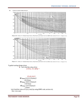
b=effective gasket selling width
2b=effective gasket pressure width
tf=thickness of flange
tf=J
hd= (G + H – 2E)/4
hg= (H - G)/4
ht= (G + H)/4
G’=mane diameter of gasket
=B + (ht-hg)](https://image.slidesharecdn.com/yaredberihunidno11004374-220601192505-5c45b677/85/Pressure-vessel-project-docx-38-320.jpg)


![PRESSURE VESSEL DESIGN
PREPAREDBY YARED BERIHUN Page 48
σhb 30mm =0.00199(1/mm2
)(336.749KN)
σhb 30mm =670.164MPa
σhb 25mm =0.003289(1/mm2
)(142.084KN)
σhb 25mm =467.31MPa
σrd=F2M
σrd70mm =0.00661(1/mm2
)(132.722KN)
σrd70mm =877.2924MPa
σrd30mm =0.004284(1/mm2
)(336.749KN)
σrd30mm =1442.643MPa
σrd25mm =0.005381(1/mm2
)(142.084KN)
σrd25mm =764.41MPa
σws=F3M
σws70mm =0.002064(1/mm2
)(132.722KN)
σws70mm =273.9382MPa
σws30mm =0.00165(1/mm2
)(336.749KN)
σws30mm =555.6358MPa
σws25mm =0.00733(1/mm2
)(142.084KN)
σws25mm =1041.4757MPa
σtg = σws -F4σrd
σtg70mm=2739.39MPa – 6.09*877.2924MPa
σtg70mm=-2603..14
σtg 30mm=555.635MPa-1.43*1442.643MPa
σtg 30mm =-206.664MPa
σtg 25mm=1041.4757MPa-1.49*764.41MPa
σtg 25mm=-97.4953MPa
The flange must be sized so that the stresses given by equations satisfy the following criteria: when
ffo=102.04MPa(14.8KPSi) is the maximum allowable design stress for the flange material at the operating conditions.
R[1] and [2]
σhb > 1.5ffo
For 70mm 45.258MPa<153.06MPa -----(unsatisfied)
For 30mm 670.164MPa > 153.06MPa ---- (satisfied)
For 25mm 467.31MPa > 153.06MPa ---- (satisfied)
σrd > ffo
For 70mm 877.2924MPa >102.02MPa ------- (satisfied)
For 30mm 1442.643MPa > 102.04MPa ------ (satisfied)
For 25mm 764.41MPa > 102.04MPa ------ (satisfied)
0.5(σhb+σrd) > ffo
For 70mm 461.27MPa > 102.04MPa --- (satisfied)](https://image.slidesharecdn.com/yaredberihunidno11004374-220601192505-5c45b677/85/Pressure-vessel-project-docx-48-320.jpg)
![PRESSURE VESSEL DESIGN
PREPAREDBY YARED BERIHUN Page 49
For 30mm 1391.48MPa > 102.04MPa --- (satisfied)
For 25mm 615.86MPa > 102.04MPa --- (satisfied)
0.5(σhb+σtg) > ffo
For 70mm -1278.94MPa<102.34 ------(unsatisfied)
For 30mm 231.978MPa > 102.04MPa --- (satisfied)
For 25mm 184.65MPa > 102.04MPa --- (satisfied)
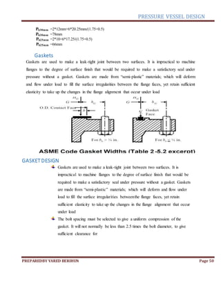
The bolt spacing must be selected to give a uniform compression of the gasket. It will not normally be less
than 2.5 times the bolt diameter, to give sufficient clearance for tightening with a wrench or spanner. The following
formula can be used to determine the maximum bolt spacing:
From the table R [1] and R [2] the material [SA-193-B7] and maximum allowable stress (fb) for the bolt is 172.37MPa
(25KPSi).
The minimum bolt area is given by
Abf=Wm/fb
Where Wm greatest of Wm1or Wm2
Nominal Dia.(mm) Wm1(KN) Wm2(KN)
70 229.2897 5.029
30 42.4327 3.132
25 39.075 2.792
Abf=Wm/fb
For 70mm nominal diameter greatest number is Wm1 =229.257KN
Abf70mm=229.2897KN/172.37MPa
Abf70mm =1330.21mm2
For 30mm nominal diameter greatest number is Wm1 =42.4327KN
…………………Abf30mm =42.4327KN/172.37MPa
Abf30mm =246.1721mm2
For 25mm nominal diameter greatest number is Wm1 =39.075KN
Abf25mm =39.075KN/172.37MPa
Abf25mm =226.6925smm2
The bolt spacing must be selected to give a uniform compression of the gasket. It will not normally be less than
2.5 times the bolt diameter, to give sufficient clearance for tightening with a wrench or spanner. The following formula
can be used to determine the maximum bolt spacing:
Pb=2db+6tf/ (m+0.5)
Where Pb-bolt pitch (spacing), mm
db- bolt diameter, mm
tf- flange thickness, mm
m- Gasket factor,1.75
Pb70mm =2*16mm+6*31.25mm/(1.75+0.5)
Pb70mm =115.33mm](https://image.slidesharecdn.com/yaredberihunidno11004374-220601192505-5c45b677/85/Pressure-vessel-project-docx-49-320.jpg)
![PRESSURE VESSEL DESIGN
PREPAREDBY YARED BERIHUN Page 51
CHAPTER FIVE
calculating wall thickness of the nozzle
To find the thickness of the nozzle
tn=PR/ (SE-0.6P)+ C.A
Where tn-thickness of the nozzle
P-maximum allowable
E-joint efficiency (E=1)
S-maximum allowablestress
R-internal radius of the pipe
C.A-corrosion allowance
For my nozzle I selects X-STGfrom the table and S=103.42MPa (15.0KPSi). R [2]
Given Table 5.1
Nominal Dia. (mm) P, MPa(PSi) C.A,mm(in) Radius(mm)
25 27.2 (3946) 1.6 (1/16) 12.5
30 16.159 (2348) 3.12 (1/8) 15
70 8.0811(1175) 6.35(1/4) 35
E=1
S=15000Psi =103.421MPa
tn will be
tn=PR/ (SE-0.6P) + C.A
tn,25mm=[(27.2MPa*12.5mm)/(103.421MPa*1-0.6*27.2MPa)]+1.6mm
tn,25mm =5.5035mm
tn,30mm=[(16.159MPa*15mm)/(103.421MPa*1-0.6*16.159MPa)]+3.12mm
tn,30mm =5.7061mm
tn,70mm=[(8.0811MPa*35mm)/(103.421MPa*1-0.6*8.0811MPa)]+6.35mm
tn,70mm =9.219mm
reinforcment of opening](https://image.slidesharecdn.com/yaredberihunidno11004374-220601192505-5c45b677/85/Pressure-vessel-project-docx-51-320.jpg)
![PRESSURE VESSEL DESIGN
PREPAREDBY YARED BERIHUN Page 52
The “equal area method” is the simplest method used for calculating the amount of reinforcement required, and
is allowedin most design codes and standards. The principle used is to provide reinforcement localto the
opening, equal in cross-sectional area to the area removed in forming the opening. If the actual thickness of the
vessel wallis greater than the minimum required to resist the loading, the excess thickness can be taken into
accountwhen estimating the area of reinforcement required. Similarly with a branch connection,if the wall
thickness of the branch or nozzleis greater than the minimum required, the excess material in the branch can be
taken into account.Any corrosion allowancemust be deducted when determining the excess thickness available
as compensation. The standards and codes differ in the areas of the branch and shell considered to be effective
for reinforcement, and should be consulted to determine the actual area allowedand the disposition of the
various types of reinforcement. For branch connections of small diameter the reinforcement area can usually be
provided by increasing the wall thickness of the branch pipe. Some design codes and standards do not require
compensation forconnections below 89 mm (3 in.) diameter. If anything, the equal area method tends to over-
estimate the compensation required and in some instances the additional material can reduce the fatigue life of
the vessel. More sophisticated methods for determining the compensation required have been introduced into
the latest editions of the codes and standards. The equal-area method is generally used forestimating the
increase in thickness required to compensate formultiple openings. R [1]
First calculatethe reinforcement area R [3]
A=D*t*F
where tr-shell thickness=0.64((D+tn) tn) 1/2 (,)
F-correctionfactor=1
D-diameter of the pipe
tn-nozzle material thickness
E-jointefficiency=1
T-Shell material thickness= (forshell 70mm or forhead 74mm)
A=D*t*F
A30mm=30mm*74mm*1=2220mm2
A70mm=70mm*74mm*1=5180mm2
tr =0.64((D+tn) tn) ½
tr30mm=0.64((30mm+5.7061)*5.7061)1/2
tr30mm =9.135mm
tr70mm=0.64((70mm+9.219)*9.219)1/2
tr70mm =49.3642mm
By taking A1 as the largest of the A11 or A12 calculating the reinforcement area of the vessel
A11= (Et-F*tr)D and A12=2(E*t-F*tr)*(t+ tn)
For 30mm tr=9.135mm](https://image.slidesharecdn.com/yaredberihunidno11004374-220601192505-5c45b677/85/Pressure-vessel-project-docx-52-320.jpg)


![PRESSURE VESSEL DESIGN
PREPAREDBY YARED BERIHUN Page 60
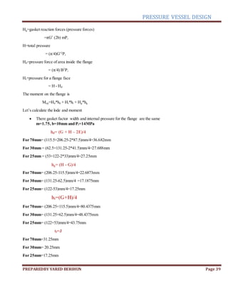
Table 5.4
QUANTITIES FORMULAS
Period of vibration, T sec T=0.0000265(H / D)2
*(w*D /t)½
Maximum allowable period of vibration, Ta
(sec)
Ta=0.80(WH /Vg) ½
s
Formula for tim
e of vibration (PRESSURE VESSEL)
Where, D = Outside diameter of vessel, 1.0542m=1054.20mm
H = Length of vesselincluding skirt, 4.571m=4571mm
g = 9.8m / sec2
gravitational acceleration
t = Thickness of skirt at the base, 70mm
V = Total shear = ZICW/Rw (calculated ahead)
=1038.6NW= Weight of tower, =394.85KN
w= weight of tower per mater of height, = 60.52KN
Putting values to get period of vibration for methanator
T = 0.0000265(6.524/1.054) 2
*(60.52*1.054*1/0.007) ½
T = 0.09691sec
Now allowable period of vibration
Ta = 0.80{W*H / V*g} ½
=0.8{(60.52*6.524)/(9.81*1038.6)}1/2
Ta = 0.1575sec
As ‘T’ is less than ‘Ta’ hence the condition is satisfied
STRESS DUE TO EARTHQUAKE
The loading condition of the tower under seismic forces is similar to that of the cantileverbeam
when the load increases uniformly towards the free end
Table 5.5
FORMULAS
Shear Moment
V=ZICW/Rw M=[FtH+(V-Ft)(2H /3)]
Mx= M(x/H)](https://image.slidesharecdn.com/yaredberihunidno11004374-220601192505-5c45b677/85/Pressure-vessel-project-docx-60-320.jpg)

![PRESSURE VESSEL DESIGN
PREPAREDBY YARED BERIHUN Page 62
= 1.25*1/(0.076644)2/3 =2.71
=2.71(should not be more than 2.75)
Rw=Numerical coefficient (use 2.9 for vessels)
E = Efficiency of welded joints = 1.0
Ft = Total horizontal seismic force at the top of the vessel, 0N(because T < 0.7)
= 0.07TV (Ft shall not exceed 0.25V)
= 0, for T < 0.7
H =Length of vessel including skirt, 4.571m=4.571mm
I = Occupancy importance coefficient (use 1.0 for
vessels)
K = Horizontal force factor (use 2.0 for vessels)
M = Maximum moment at the base,
Nm
Mx= Moment at distance x, Nm
S = Numerical coefficient for site structure resonance
= 1.0
The product CS shall not exceed 0.14
W = Weight of the vessel, 394.85KNZ =
Seismic factor
= 0.15
Shear = (0.15*1*0.0299*394.85KN)/2.9 V =
1038.6N
Ft = 0.07*T*V =0.07*0.08644*1038.6N=6.284N
0.25V= 259.65N
As condition is that Ft should not exceed 0.25V so it is satisfied for methanator
Therefore Moment
M = [6.284*4.5124 + (1038.6-6.284)*(2*4.524/3)] M
=3140.089Nm
Moment at skirt to head joint
Mt = M(x/H) where x=H/3=4.57m/3=1.5233m
=3140.089Nm*(1.5233m/4.57m)
=1046.67Nm](https://image.slidesharecdn.com/yaredberihunidno11004374-220601192505-5c45b677/85/Pressure-vessel-project-docx-62-320.jpg)


![office final ppt [7760835] final update](https://cdn.slidesharecdn.com/ss_thumbnails/aba3fa8b-edf3-48e1-ba61-7fb4f65dc95a-160410081228-thumbnail.jpg?width=640&height=640&fit=bounds)