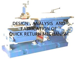
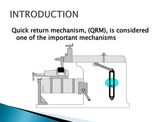
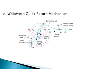
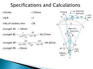
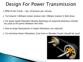
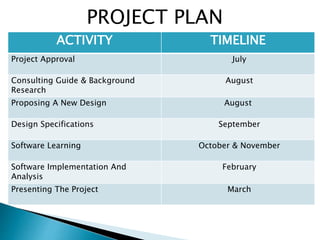
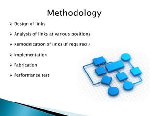
PROJECT SEMINAR
PROJECT GUIDE: D.SRINIVAS RAO (ASSOCIATE HEAD)
BY : MD NASEERUDDIN SHAH 1604-11-736-072
IBRAHIM MD AMEENUDDIN 1604-11-736-075
MOHD JALEELUDDIN 1604-11-736-105
MD SOHAIL KURANI 1604-11-736-135
 Introduction
 Basic Concepts
 Defining the Problem
 Overcoming the Problem
 Design
 Analysis
 Fabrication
 Application
 Conclusion
 Project Plan
 Methodology
 Bibliography
Quick return mechanism, (QRM), is considered
one of the important mechanisms
 Mechanism : It transforms or transfer motion
 Link: Machine element which moves relative
to other elements (machine)
a) Rigid link
b) Flexible link
c) Fluid link
 Kinematic pair : When two links are joint they
constitute a pair
 Joints : Junction of links
Type of motions possible between links
• Revolute
• Sliding
Number of Links : 4
Number of Pairs : 4
Number of Fixed Links : 4
 Modification of a basic four bar chain
 It consists of one sliding pair, three turning
pair
 Method of obtaining different mechanisms by
fixing different links in a kinematic chain
 No. of Inversions possible = No. of links
 No. of Inversions for four bar mechanism = 4
 Pendulum Pump
 Oscillating Cylinder Engine
 Rotary Internal Combustion Engine
 Crank and Slotted Lever Quick Return Mechanism
 Whitworth Quick Return Mechanism
Lower Quick Return Ratio
Vibrations due to non linear velocity
Defining Problem
Rigid structure
Selection of material
Usage of Brass Bearings
Overcoming the problem
1.Forces acting on each link
2.Selecting materials
3.Suitable cross section
4.Link lengths
5.Machine power
 Factors To Be Considered In Design
Design
Specifications and Calculations
Stroke =120mm
Q.R =3
No.of strokes/min =50
Length AC = 40mm
Length BC = = = 56.57mm
Length AP = = =84.85mm
Length PR = 20mm
Dynamic Analysis
Calculation Of Forces
F6 = Τsteel *d* w
F6 = 225*4*5
F6 = 4500N
F2 = F6
F5 =
F5 =
F5 =6364N
F4 = F5
Design of Crank
Maximum force acting on Crank = 4500 * Impact Load Factor
= 4500*2 = 9000N
Cross-sectional Area Of Crank = Max Load / Permissible Stress
= 9000/200 = 45mm2 ………..1
Considering Rectangular Cross-Section, b=2d.
C.S Area = b*d = 2d*d ………..2
Equating 1 and 2
2d*d = 45
d = 5mm
b = 10mm
Design Of Slotted Bar
Maximum Force acting on Slotted Bar = 6364 * Impact Load Factor
= 6364*2 = 12728N
Cross-sectional Area Of Crank = Max Load / Permissible Stress
= 12728/200 = 64mm2 ………..1
Considering Rectangular Cross-Section, b=2d.
C.S Area = b*d = 2d*d ………..2
Equating 1 and 2
2d*d = 64
d = 6mm
b = 12mm
Power Calculations
From Specifications
Mean Velocity = Stroke length * No. of strokes/mm
= 120*100
= 12 m/min
Power = Cutting Force * Mean Velocity
= 4500*(12/60)
= 900 watts (1.2 HP)
Including Friction and Inertia Forces 2HP Motor is
required.
Design For Power Transmission
 RPM of the Crank = No. of Strokes per minute
 To Convert 1400rpm motor motion into 100rpm motion V-Belt drive
 For given loads Phosphor Bronze Bushings of required thickness should
be used at Pin Joints between the links
 Due to large fluctuations in loads Vibrations are induced.
 To minimize these Vibrations, Cast Iron or Wooden Frame should be used
 Positional Analysis
 Velocity Analysis
 Acceleration Analysis
 Force Analysis
Analysis of Quick Return
Mechanism
Data Acquisition System
 System takes the analog output from the various sensors and
converts them into digital values.
 Digital analogous value is fed into the processing unit.
 The computer uses software called KDM (Kinematics and
Dynamics Of Machines).
The needed values and their characteristic curves are plotted
by the software and the output is recorded.
Analysis Softwares
Motion simulation softwares
CAE tools
 Catia
 UG-NX
 NX I-DEAS
 SolidWorks
To study planar mechanism kinematics
 MatLab
 Simulink
 MapleSim
 SolidWorks
Software Analysis Procedure
 Modeling the linkage using the motion simulation
application (SolidWorks).
 Import the model into Ansys
 Analyse the meshed model in Ansys (Structural)
 Study planar mechanism kinematics (position,
velocity and acceleration) of the model using
SolidWorks
 Position analysis includes
the position of links at
different crank angle
 From this we can
determine the extreme
positions of the mechanism
Position Analysis
 Velocity Analysis
deals with variation
in velocity of
slider at different
instances
Velocity Analysis
Ground length = 25mm
 When crank radius
tends to ground length
, QRR tends to infinite
Crank radius = 10mm
 When ground length
tends to crank radius
length , QRR tends to
infinite
QRR Vs Crank Radius , QRR Vs Ground length
Fabrication
Fabrication is an industrial term refers to building metal
structures by cutting, machining and drilling.
The fabrication of quick return mechanism unit involves:
 Cutting
 Drilling
 Machining
 Welding
 Grinding
 Carpentry work
Fabrication of Crank and Connecting Rod
 The cutting operation can be carried out
in workshop
 For better accuracy , ease and surface
finish shaping machine is preferred
 Drilling of holes at ends of both sides
 The holes are drilled with respect to
suitable dimensions by using drilling
machine
Fabrication of Slider
 Wood is cut in suitable dimension
The carpentry operations are performed here
Fabrication of Frame
 A frame has to withstand the load of the crank as well
as the connecting rod to avoid disturbance
A wood plank may be chosen to avoid breakage and
also prevent noise
The frame is to be cut into required dimensions using
handsaw and chisel
The frame is to be tightened with the help of adhesives
and screws for rigid support
Grinding may be done for a smooth surface finish
 Machine tools
 Shaping machines
 Power-driven saws
 Slotter machines
Applications
Conclusion
The purpose of the project is to design and construct a
kinematic quick return device. Beginning with general
research into quick return devices, the project has to follow
a methodology of determining the design space, building a
mathematical model and then implementing that model. The
design process as a whole has to be experienced from start
to finish and is to be incorporated as a multitude of
different aspects of engineering. Designing this mechanism
will be an excellent experience in tackling a design project
where the majority of constraints are self-imposed. The
final design produced will be an effective one. Hopefully,
with a little work, the mechanism will be operational and
seen by future kinematics students for years to come.
ACTIVITY TIMELINE
Project Approval July
Consulting Guide & Background
Research
August
Proposing A New Design August
Design Specifications September
Software Learning October & November
Software Implementation And
Analysis
February
Presenting The Project March
PROJECT PLAN
Methodology
 Design of links
 Analysis of links at various positions
 Remodification of links (If required )
 Implementation
 Fabrication
 Performance test
BIBLIOGRAPHY
 Theory of Machines by R.S. Khurmi and J.K.Gupta
 Design of Machine Elements by R.S. Khurmi and J.K.Gupta
 Theory of Machines by Ratan
 Manufacturing Technology by P N Rao
http://www.morldtechgossips.com/2012/05/fabrication-of-
slider-crank-unit.html
QRM Project

QRM Project

  • 1.
    PROJECT SEMINAR PROJECT GUIDE:D.SRINIVAS RAO (ASSOCIATE HEAD) BY : MD NASEERUDDIN SHAH 1604-11-736-072 IBRAHIM MD AMEENUDDIN 1604-11-736-075 MOHD JALEELUDDIN 1604-11-736-105 MD SOHAIL KURANI 1604-11-736-135
  • 3.
     Introduction  BasicConcepts  Defining the Problem  Overcoming the Problem  Design  Analysis  Fabrication  Application  Conclusion  Project Plan  Methodology  Bibliography
  • 4.
    Quick return mechanism,(QRM), is considered one of the important mechanisms
  • 5.
     Mechanism :It transforms or transfer motion
  • 6.
     Link: Machineelement which moves relative to other elements (machine) a) Rigid link b) Flexible link c) Fluid link
  • 7.
     Kinematic pair: When two links are joint they constitute a pair  Joints : Junction of links Type of motions possible between links • Revolute • Sliding
  • 8.
    Number of Links: 4 Number of Pairs : 4 Number of Fixed Links : 4
  • 9.
     Modification ofa basic four bar chain  It consists of one sliding pair, three turning pair
  • 10.
     Method ofobtaining different mechanisms by fixing different links in a kinematic chain  No. of Inversions possible = No. of links  No. of Inversions for four bar mechanism = 4
  • 11.
     Pendulum Pump Oscillating Cylinder Engine
  • 12.
     Rotary InternalCombustion Engine  Crank and Slotted Lever Quick Return Mechanism
  • 13.
     Whitworth QuickReturn Mechanism
  • 14.
    Lower Quick ReturnRatio Vibrations due to non linear velocity Defining Problem Rigid structure Selection of material Usage of Brass Bearings Overcoming the problem
  • 15.
    1.Forces acting oneach link 2.Selecting materials 3.Suitable cross section 4.Link lengths 5.Machine power  Factors To Be Considered In Design Design
  • 16.
    Specifications and Calculations Stroke=120mm Q.R =3 No.of strokes/min =50 Length AC = 40mm Length BC = = = 56.57mm Length AP = = =84.85mm Length PR = 20mm
  • 17.
    Dynamic Analysis Calculation OfForces F6 = Τsteel *d* w F6 = 225*4*5 F6 = 4500N F2 = F6 F5 = F5 = F5 =6364N F4 = F5
  • 18.
    Design of Crank Maximumforce acting on Crank = 4500 * Impact Load Factor = 4500*2 = 9000N Cross-sectional Area Of Crank = Max Load / Permissible Stress = 9000/200 = 45mm2 ………..1 Considering Rectangular Cross-Section, b=2d. C.S Area = b*d = 2d*d ………..2 Equating 1 and 2 2d*d = 45 d = 5mm b = 10mm
  • 19.
    Design Of SlottedBar Maximum Force acting on Slotted Bar = 6364 * Impact Load Factor = 6364*2 = 12728N Cross-sectional Area Of Crank = Max Load / Permissible Stress = 12728/200 = 64mm2 ………..1 Considering Rectangular Cross-Section, b=2d. C.S Area = b*d = 2d*d ………..2 Equating 1 and 2 2d*d = 64 d = 6mm b = 12mm
  • 20.
    Power Calculations From Specifications MeanVelocity = Stroke length * No. of strokes/mm = 120*100 = 12 m/min Power = Cutting Force * Mean Velocity = 4500*(12/60) = 900 watts (1.2 HP) Including Friction and Inertia Forces 2HP Motor is required.
  • 21.
    Design For PowerTransmission  RPM of the Crank = No. of Strokes per minute  To Convert 1400rpm motor motion into 100rpm motion V-Belt drive  For given loads Phosphor Bronze Bushings of required thickness should be used at Pin Joints between the links  Due to large fluctuations in loads Vibrations are induced.  To minimize these Vibrations, Cast Iron or Wooden Frame should be used
  • 22.
     Positional Analysis Velocity Analysis  Acceleration Analysis  Force Analysis Analysis of Quick Return Mechanism
  • 23.
    Data Acquisition System System takes the analog output from the various sensors and converts them into digital values.  Digital analogous value is fed into the processing unit.  The computer uses software called KDM (Kinematics and Dynamics Of Machines). The needed values and their characteristic curves are plotted by the software and the output is recorded.
  • 24.
    Analysis Softwares Motion simulationsoftwares CAE tools  Catia  UG-NX  NX I-DEAS  SolidWorks To study planar mechanism kinematics  MatLab  Simulink  MapleSim  SolidWorks
  • 25.
    Software Analysis Procedure Modeling the linkage using the motion simulation application (SolidWorks).  Import the model into Ansys  Analyse the meshed model in Ansys (Structural)  Study planar mechanism kinematics (position, velocity and acceleration) of the model using SolidWorks
  • 26.
     Position analysisincludes the position of links at different crank angle  From this we can determine the extreme positions of the mechanism Position Analysis
  • 27.
     Velocity Analysis dealswith variation in velocity of slider at different instances Velocity Analysis
  • 28.
    Ground length =25mm  When crank radius tends to ground length , QRR tends to infinite Crank radius = 10mm  When ground length tends to crank radius length , QRR tends to infinite QRR Vs Crank Radius , QRR Vs Ground length
  • 29.
    Fabrication Fabrication is anindustrial term refers to building metal structures by cutting, machining and drilling. The fabrication of quick return mechanism unit involves:  Cutting  Drilling  Machining  Welding  Grinding  Carpentry work
  • 30.
    Fabrication of Crankand Connecting Rod  The cutting operation can be carried out in workshop  For better accuracy , ease and surface finish shaping machine is preferred  Drilling of holes at ends of both sides  The holes are drilled with respect to suitable dimensions by using drilling machine
  • 31.
    Fabrication of Slider Wood is cut in suitable dimension The carpentry operations are performed here Fabrication of Frame  A frame has to withstand the load of the crank as well as the connecting rod to avoid disturbance A wood plank may be chosen to avoid breakage and also prevent noise The frame is to be cut into required dimensions using handsaw and chisel The frame is to be tightened with the help of adhesives and screws for rigid support Grinding may be done for a smooth surface finish
  • 32.
     Machine tools Shaping machines  Power-driven saws  Slotter machines Applications
  • 33.
    Conclusion The purpose ofthe project is to design and construct a kinematic quick return device. Beginning with general research into quick return devices, the project has to follow a methodology of determining the design space, building a mathematical model and then implementing that model. The design process as a whole has to be experienced from start to finish and is to be incorporated as a multitude of different aspects of engineering. Designing this mechanism will be an excellent experience in tackling a design project where the majority of constraints are self-imposed. The final design produced will be an effective one. Hopefully, with a little work, the mechanism will be operational and seen by future kinematics students for years to come.
  • 34.
    ACTIVITY TIMELINE Project ApprovalJuly Consulting Guide & Background Research August Proposing A New Design August Design Specifications September Software Learning October & November Software Implementation And Analysis February Presenting The Project March PROJECT PLAN
  • 35.
    Methodology  Design oflinks  Analysis of links at various positions  Remodification of links (If required )  Implementation  Fabrication  Performance test
  • 36.
    BIBLIOGRAPHY  Theory ofMachines by R.S. Khurmi and J.K.Gupta  Design of Machine Elements by R.S. Khurmi and J.K.Gupta  Theory of Machines by Ratan  Manufacturing Technology by P N Rao http://www.morldtechgossips.com/2012/05/fabrication-of- slider-crank-unit.html