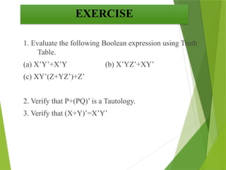
EXERCISE
1. Evaluate thefollowing Boolean expression using Truth
Table.
(a) X’Y’+X’Y (b) X’YZ’+XY’
(c) XY’(Z+YZ’)+Z’
2. Verify that P+(PQ)’ is a Tautology.
3. Verify that (X+Y)’=X’Y’
3.
AND GATE
So whilegoing out of the house you set the "Alarm
Switch" and if the burglar enters he will set the "Person switch",
and tada the alarm will ring.
PRACTICAL APPLICATIONS OF LOGIC GATES
4.
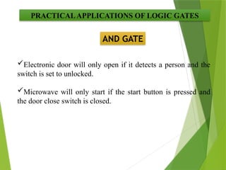
AND GATE
PRACTICALAPPLICATIONS OFLOGIC GATES
Electronic door will only open if it detects a person and the
switch is set to unlocked.
Microwave will only start if the start button is pressed and
the door close switch is closed.
5.
OR GATE
You wouldof course want your doorbell to ring
when someone presses either the front door switch or the
back door switch..(nice)
PRACTICALAPPLICATIONS OF LOGIC GATES
6.
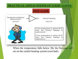
NOT GATE
When thetemperature falls below 20c the Not gate will
set on the central heating system (cool huh).
PRACTICAL APPLICATIONS OF LOGIC GATES
7.
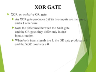
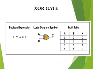
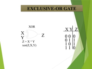
XOR GATE
XOR,or exclusive OR, gate
An XOR gate produces 0 if its two inputs are the same,
and a 1 otherwise
Note the difference between the XOR gate
and the OR gate; they differ only in one
input situation
When both input signals are 1, the OR gate produces a 1
and the XOR produces a 0
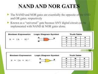
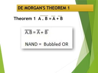
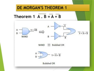
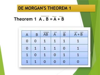
NAND AND NORGATES
The NAND and NOR gates are essentially the opposite of the AND
and OR gates, respectively
Known as a “universal” gate because ANY digital circuit can be
implemented with NAND & NOR gates alone.
10.
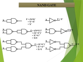
NAND GATE
X
X
F =(X•X)’
= X’+X’
= X’
X
Y
Y
F = ((X•Y)’)’
= (X’+Y’)’
= X’’•Y’’
= X•Y
F = (X’•Y’)’
= X’’+Y’’
= X+Y
X
X
F = X’
X
Y
Y
F X•Y
F = X+Y
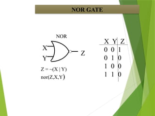
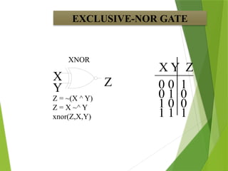
EXCLUSIVE-NOR GATE
X YZ
XNOR
X
Y Z 0 0 1
0 1 0
1 0 0
1 1 1
Z = ~(X ^ Y)
Z = X ~^ Y
xnor(Z,X,Y)
14.
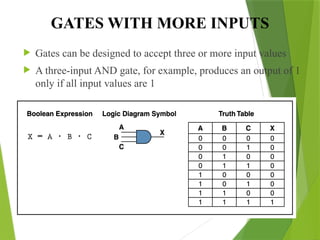
GATES WITH MOREINPUTS
Gates can be designed to accept three or more input values
A three-input AND gate, for example, produces an output of 1
only if all input values are 1
15.
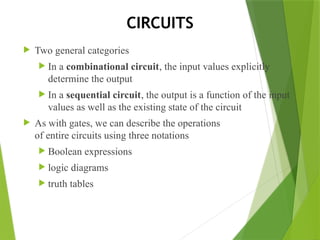
CIRCUITS
Two generalcategories
In a combinational circuit, the input values explicitly
determine the output
In a sequential circuit, the output is a function of the input
values as well as the existing state of the circuit
As with gates, we can describe the operations
of entire circuits using three notations
Boolean expressions
logic diagrams
truth tables
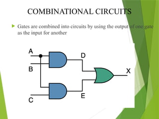
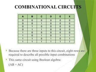
COMBINATIONAL CIRCUITS
Becausethere are three inputs to this circuit, eight rows are
required to describe all possible input combinations
This same circuit using Boolean algebra:
(AB + AC)
18.
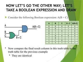
NOW LET’S GOTHE OTHER WAY; LET’S
TAKE A BOOLEAN EXPRESSION AND DRAW
Consider the following Boolean expression: A(B + C)
• Now compare the final result column in this truth table to the
truth table for the previous example
• They are identical
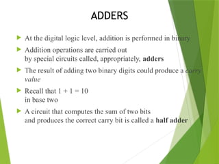
ADDERS
At thedigital logic level, addition is performed in binary
Addition operations are carried out
by special circuits called, appropriately, adders
The result of adding two binary digits could produce a carry
value
Recall that 1 + 1 = 10
in base two
A circuit that computes the sum of two bits
and produces the correct carry bit is called a half adder
21.
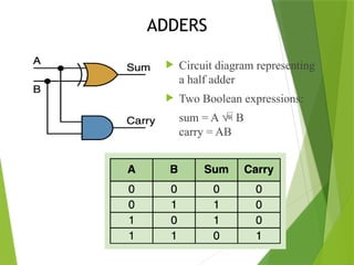
ADDERS
Circuit diagramrepresenting
a half adder
Two Boolean expressions:
sum = A B
carry = AB
22.
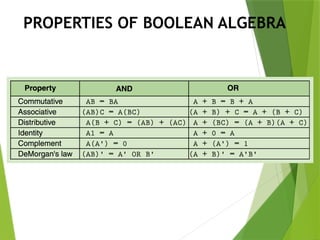
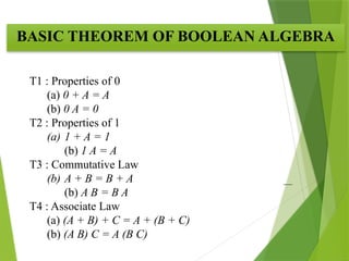
BASIC THEOREM OFBOOLEAN ALGEBRA
T1 : Properties of 0
(a) 0 + A = A
(b) 0 A = 0
T2 : Properties of 1
(a) 1 + A = 1
(b) 1 A = A
T3 : Commutative Law
(b) A + B = B + A
(b) A B = B A
T4 : Associate Law
(a) (A + B) + C = A + (B + C)
(b) (A B) C = A (B C)
23.
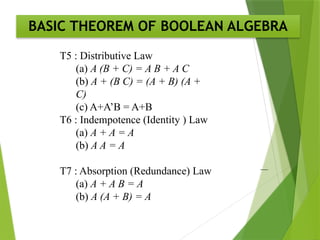
BASIC THEOREM OFBOOLEAN ALGEBRA
T5 : Distributive Law
(a) A (B + C) = A B + A C
(b) A + (B C) = (A + B) (A +
C)
(c) A+A’B = A+B
T6 : Indempotence (Identity ) Law
(a) A + A = A
(b) A A = A
T7 : Absorption (Redundance) Law
(a) A + A B = A
(b) A (A + B) = A
24.
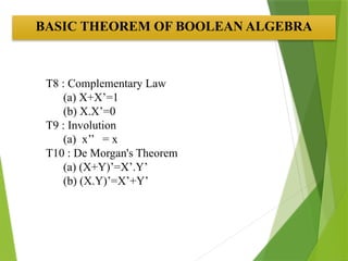
T8 : ComplementaryLaw
(a) X+X’=1
(b) X.X’=0
T9 : Involution
(a) x’’ = x
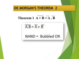
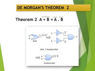
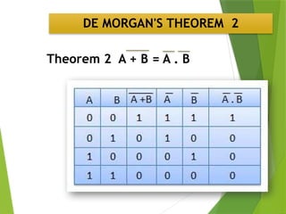
T10 : De Morgan's Theorem
(a) (X+Y)’=X’.Y’
(b) (X.Y)’=X’+Y’
BASIC THEOREM OF BOOLEAN ALGEBRA


![Chapter 3 computer Boolean Algebra 2[1].pptx](https://cdn.slidesharecdn.com/ss_thumbnails/chapter3booleanalgebra21-240928031107-5861eb7e-thumbnail.jpg?width=640&height=640&fit=bounds)