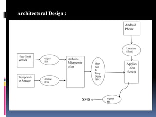
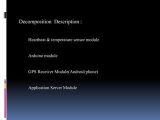
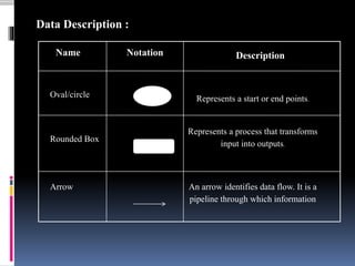
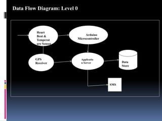
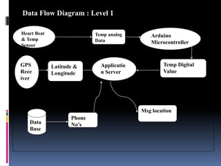
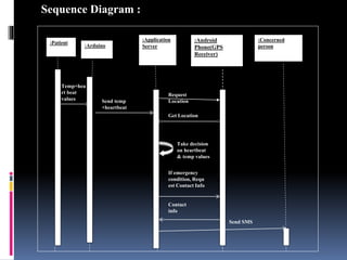
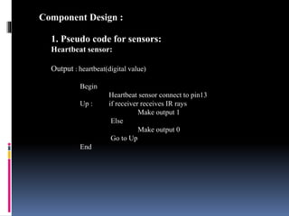
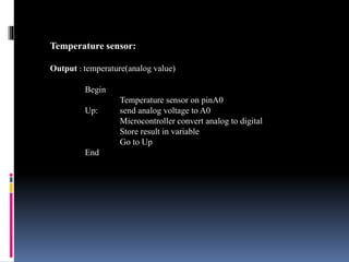
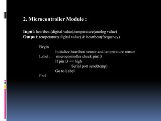
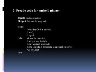
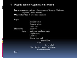
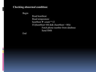
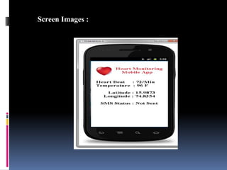
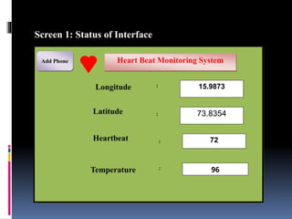
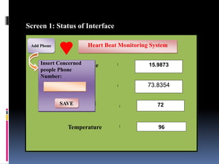
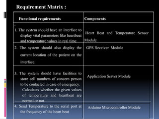
Presented By
College Name: Hirasugar Institute of Technology, Nidasoshi.
Department: Computer Science and Engineering.
Purpose :
A software design document (SDD) is a written
description of a software product, that a software designer writes
in order to give a software development team an overall guidance
of the architecture of the software project.
Existing System: Proposed solution :
wired
System architecture :
Heartbeat
Sensor
Signal
Bit
Temperatu
re Sensor
Arduino
Microcontr
oller
Applica
-tion
Server
Android
Phone
Location
(float)
Heart
beat
&
Temp
Digita
l (int)Anolog
0-5V
Signal
Bit
SMS
Architectural Design :
Decomposition Description :
Heartbeat & temperature sensor module
Arduino module
GPS Receiver Module(Android phone)
Application Server Module
Oval/circle Represents a start or end points.
Rounded Box
Represents a process that transforms
input into outputs.
Arrow An arrow identifies data flow. It is a
pipeline through which information
Name Notation Description
Data Description :
Data Flow Diagram : Level 0
Heart
Beat &
Temperat
ure Sensor
Arduino
Microcontroller
GPS
Receiver
Applicatio
n Server Data
Store
SMS
Data Flow Diagram: Level 0
Data Flow Diagram : Level 1
Temp analog
Data
Arduino
Microcontroller
Temp Digital
Value
Applicatio
n Server
Latitude &
Longitude
GPS
Rece
iver
Msg location
Phone
No’sData
Base
Heart Beat
& Temp
Sensor
Sequence Diagram :
:Android
Phone(GPS
Receiver)
:Concerned
person
:Patient
:Application
Server:Arduino
Temp+hea
rt beat
values Send temp
+heartbeat
If emergency
condition, Requ
est Contact Info
Send SMS
Request
Location
Get Location
Take decision
on heartbeat
& temp values
Contact
info
Sequence Diagram :
1. Pseudo code for sensors:
Heartbeat sensor:
Output : heartbeat(digital value)
Begin
Heartbeat sensor connect to pin13
Up : if receiver receives IR rays
Make output 1
Else
Make output 0
Go to Up
End
Component Design :
Temperature sensor:
Output : temperature(analog value)
Begin
Temperature sensor on pinA0
Up: send analog voltage to A0
Microcontroller convert analog to digital
Store result in variable
Go to Up
End
2. Microcontroller Module :
Input: heartbeat(digital value),temperature(anolog value)
Output: temperature(digital value) & heartbeat(frequency)
Begin
Initialize heartbeat sensor and temperature sensor
Label : microcontroller check pin13
If pin13 == high
Serial port send(temp)
Go to Label
End
3. Pseudo code for android phone :
Input: start application
Output: latitude & longitude
Begin
Initialize GPS in android
Lat=0;
Lng=0;
Label : determine location
Lat= current latitude
Lng= current longitude
Send latitude & longitude to application server
Go to Label
End
4. Pseudo code for Application server :
Input: temperature(digital value),heartbeat(frequency),latitude,
longitude, phone number
Output: heartbeat & abnormal condition
Begin
Initialize timer
Open serial port
Timer start
Mainloop : count=0;
Label : read from serial port temp
Display temp
Count++;
If timer time end
Go to Disp
Else
Go to label
Disp : display counter (heartbeat)
Go to Mainloop
End
Checking abnormal condition:
Begin
Read heartbeat
Read temperature
heartbeat  count * 12
If ((heartbeat<60) && (heartbeat > 80))
Fetch phone number from database
Send SMS
End
Screen Images :
Screen 1: Status of Interface
Heart Beat Monitoring System
72
96
15.9873
73.8354
:
:
:
:
Add Phone
Latitude
Temperature
Heartbeat
Longitude
Screen 1: Status of Interface
Heart Beat Monitoring System
72
96
15.9873
73.8354
:
:
:
:
Add Phone
Latitude
Temperature
Heartbeat
LongitudeInsert Concerned
people Phone
Number:
SAVESAVE
Functional requirements Components
.
1. The system should have an interface to
display vital parameters like heartbeat
and temperature values in real time.
Heart Beat and Temperature Sensor
Module
2. The system should also display the
current location of the patient on the
interface.
GPS Receiver Module
3. The system should have facilities to
store cell numbers of concern person
to be contacted in case of emergency.
Calculates whether the given values
of temperature and heartbeat are
normal or not.
Application Server Module
4. Send Temperature to the serial port at
the frequency of the heart beat
Arduino Microcontroller Module
Requirement Matrix :
Any questions ?

Pptsdd ak

  • 2.
    Presented By College Name:Hirasugar Institute of Technology, Nidasoshi. Department: Computer Science and Engineering.
  • 3.
    Purpose : A softwaredesign document (SDD) is a written description of a software product, that a software designer writes in order to give a software development team an overall guidance of the architecture of the software project. Existing System: Proposed solution : wired
  • 4.
    System architecture : Heartbeat Sensor Signal Bit Temperatu reSensor Arduino Microcontr oller Applica -tion Server Android Phone Location (float) Heart beat & Temp Digita l (int)Anolog 0-5V Signal Bit SMS Architectural Design :
  • 5.
    Decomposition Description : Heartbeat& temperature sensor module Arduino module GPS Receiver Module(Android phone) Application Server Module
  • 6.
    Oval/circle Represents astart or end points. Rounded Box Represents a process that transforms input into outputs. Arrow An arrow identifies data flow. It is a pipeline through which information Name Notation Description Data Description :
  • 7.
    Data Flow Diagram: Level 0 Heart Beat & Temperat ure Sensor Arduino Microcontroller GPS Receiver Applicatio n Server Data Store SMS Data Flow Diagram: Level 0
  • 8.
    Data Flow Diagram: Level 1 Temp analog Data Arduino Microcontroller Temp Digital Value Applicatio n Server Latitude & Longitude GPS Rece iver Msg location Phone No’sData Base Heart Beat & Temp Sensor
  • 9.
    Sequence Diagram : :Android Phone(GPS Receiver) :Concerned person :Patient :Application Server:Arduino Temp+hea rtbeat values Send temp +heartbeat If emergency condition, Requ est Contact Info Send SMS Request Location Get Location Take decision on heartbeat & temp values Contact info Sequence Diagram :
  • 10.
    1. Pseudo codefor sensors: Heartbeat sensor: Output : heartbeat(digital value) Begin Heartbeat sensor connect to pin13 Up : if receiver receives IR rays Make output 1 Else Make output 0 Go to Up End Component Design :
  • 11.
    Temperature sensor: Output :temperature(analog value) Begin Temperature sensor on pinA0 Up: send analog voltage to A0 Microcontroller convert analog to digital Store result in variable Go to Up End
  • 12.
    2. Microcontroller Module: Input: heartbeat(digital value),temperature(anolog value) Output: temperature(digital value) & heartbeat(frequency) Begin Initialize heartbeat sensor and temperature sensor Label : microcontroller check pin13 If pin13 == high Serial port send(temp) Go to Label End
  • 13.
    3. Pseudo codefor android phone : Input: start application Output: latitude & longitude Begin Initialize GPS in android Lat=0; Lng=0; Label : determine location Lat= current latitude Lng= current longitude Send latitude & longitude to application server Go to Label End
  • 14.
    4. Pseudo codefor Application server : Input: temperature(digital value),heartbeat(frequency),latitude, longitude, phone number Output: heartbeat & abnormal condition Begin Initialize timer Open serial port Timer start Mainloop : count=0; Label : read from serial port temp Display temp Count++; If timer time end Go to Disp Else Go to label Disp : display counter (heartbeat) Go to Mainloop End
  • 15.
    Checking abnormal condition: Begin Readheartbeat Read temperature heartbeat  count * 12 If ((heartbeat<60) && (heartbeat > 80)) Fetch phone number from database Send SMS End
  • 16.
  • 17.
    Screen 1: Statusof Interface Heart Beat Monitoring System 72 96 15.9873 73.8354 : : : : Add Phone Latitude Temperature Heartbeat Longitude
  • 18.
    Screen 1: Statusof Interface Heart Beat Monitoring System 72 96 15.9873 73.8354 : : : : Add Phone Latitude Temperature Heartbeat LongitudeInsert Concerned people Phone Number: SAVESAVE
  • 19.
    Functional requirements Components . 1.The system should have an interface to display vital parameters like heartbeat and temperature values in real time. Heart Beat and Temperature Sensor Module 2. The system should also display the current location of the patient on the interface. GPS Receiver Module 3. The system should have facilities to store cell numbers of concern person to be contacted in case of emergency. Calculates whether the given values of temperature and heartbeat are normal or not. Application Server Module 4. Send Temperature to the serial port at the frequency of the heart beat Arduino Microcontroller Module Requirement Matrix :
  • 21.