The document appears to be a project report for developing an online voting system for college elections. It includes sections on introduction, requirements analysis, project management, design, testing, and references. The introduction describes the problem of low voter turnout in traditional voting and proposes an online system to allow students to vote from anywhere. The requirements analysis section includes data flow diagrams and a data dictionary. The project management section estimates the project scope in function points, effort in person-months, and schedule. It also includes a risk table.


![9|Page
Username = Name|Digit
Name = First + Middle + Last
First = [a|b|c_ _ _ _ _ _ _|z|A|B|C_ _ _ _ _ _|Z]*
Middle = [a|b|c_ _ _ _ _ _ _|z|A|B|C_ _ _ _ _ _|Z]*
Last = [a|b|c_ _ _ _ _ _ _|z|A|B|C_ _ _ _ _ _|Z]*
Digit=[0|1|2|3|_ _ _ _ _ |9]*
Successful = Done
Unsuccessful = Not Done
Authenticated = Done
Status = Yes/No
Receipt = [Code] + digit + digit + digit + digit + Name
Password = [word] | digit
Word = [0|1|2|3|_ _ _ _ _|9]*
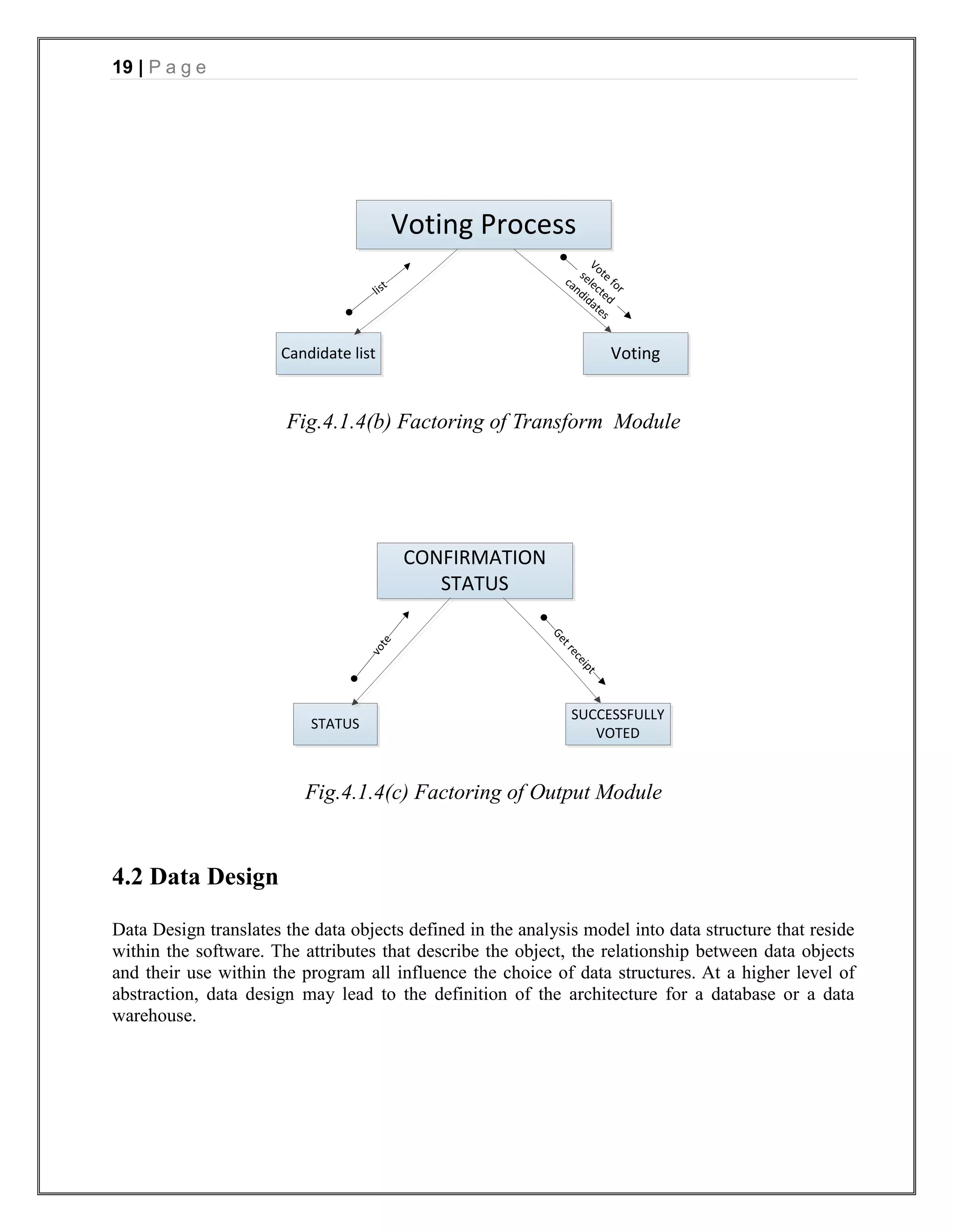
Fig.2.2 Data Dictionary (DD)
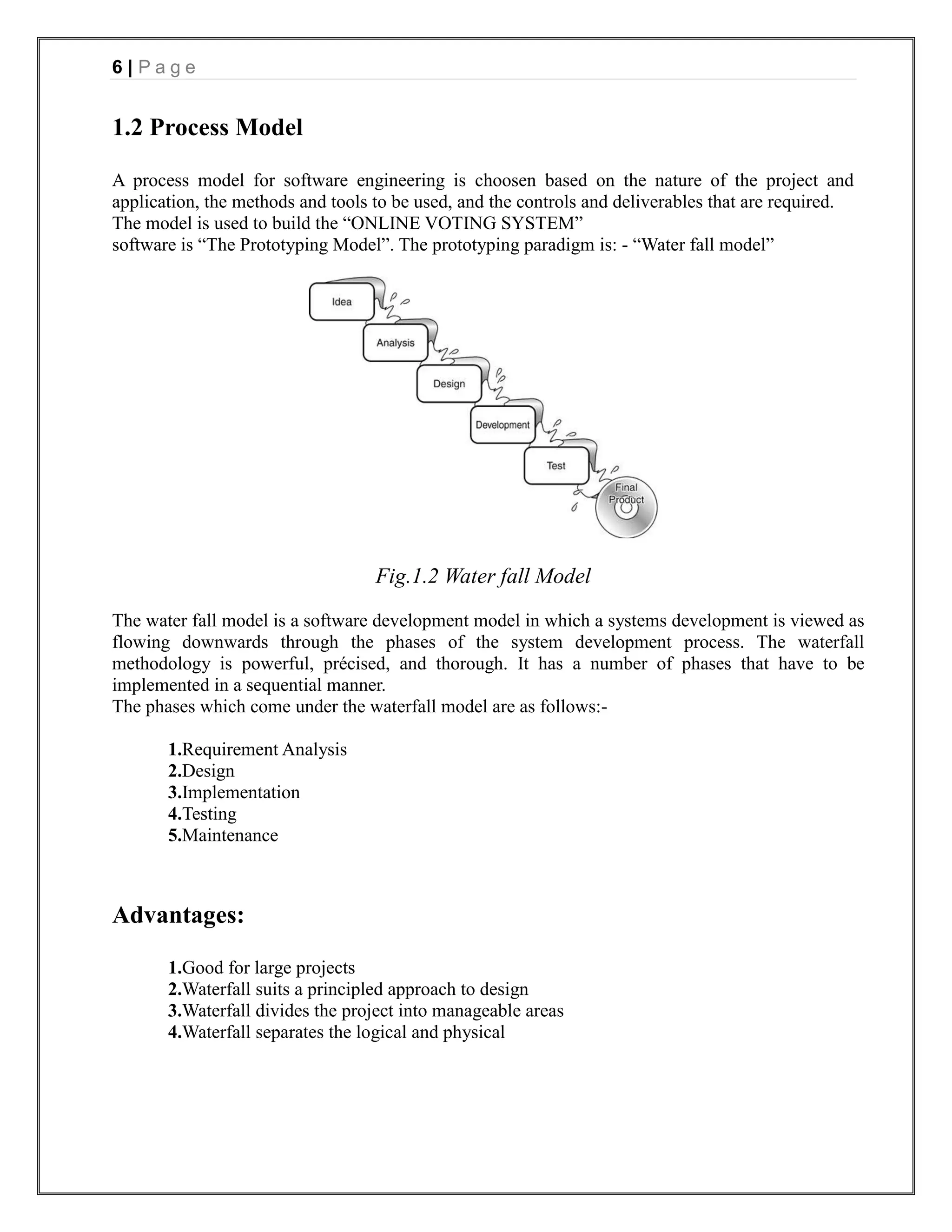
3. PROJECT MANAGEMENT
Project management involves the planning, monitoring, and control of the people, process, and
events that occur as software evolves from a preliminary concept to an operational
implementation. Project managers plan, monitor, and control the work of a team of software
engineers. Effective software project management focuses on the four P‟ s: people, product,
process, and project.
3.1 Function Points
Function-oriented software metrics use a measure of the functionality delivered b y the application
as a normalization value. Since, ―functionality‖ cannot be measured directly; it must be derived
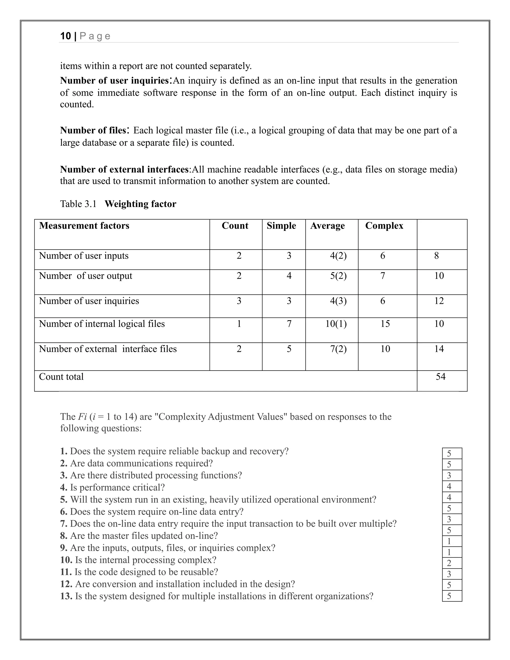
indirectly using other direct measures. Function points are computed by completing the table 4.1.
Five information domain characteristics are determined and counts are provided in the appropriate
table location. Information domain values are defined in the following manner:
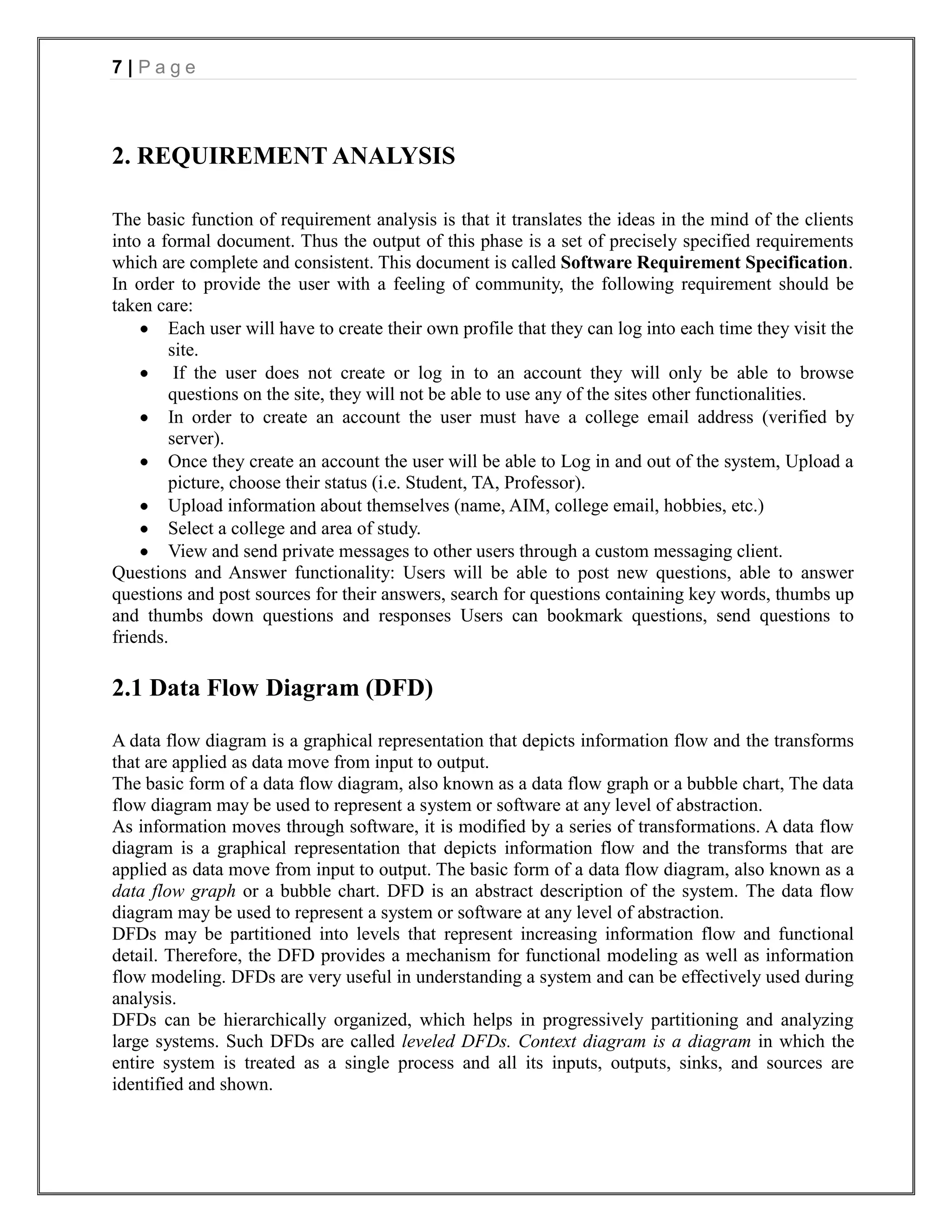
Number of user inputs:Each user input that provides distinct application oriented data to the
software is counted. Inputs should be distinguished from inquiries, which are counted separately.
Number of user outputs: Each user output that provides application oriented information to the
user is counted. In this context output refers to reports, screens, error messages, etc. Individual data](https://image.slidesharecdn.com/onlinevotingsystemproject-130416093803-phpapp01/75/Online-voting-system-project-9-2048.jpg)
![11 | P a g e
14. Is the application designed to facilitate change and ease of use by the user?
Once these data have been collected, a complexity value is associated with each count.
Organizations that use function point methods develop criteria for determining whether a particular
entry is simple, average, or complex. To compute function points (FP), the following relationship
is used:
FP = count total *[0.65 + 0.01 *Σ (Fi)]
= 54*(0.65 + 0.01*51)
=54*1.16
=62 (approx.)
Where count total is the sum of all FP entries obtained from Figure.
3.2 ESTIMATING EFFORTS
Barry Boehm introduced a hierarchy of software estimation models bearing the name COCOMO,
for COnstructive COst MOdel. The original COCOMO model became one of the most widely used
and discussed software cost estimation models in the industry. The COCOMO II application
composition model uses object points.
The object point is an indirect software measure that is computed using counts of the no. of screens
(user interface), reports and components likely to be required to build the application. Each object
instance is classified into one of three complexity levels using criteria suggested by Boehm.
Once complexity is determined, the number of screens, reports, and components are weighted. The
object point count is then determined by multiplying the original number of object instances by the
weighting factor in and summing to obtain a total object point count. When component-based
development or general software reuse is to be applied, the percent of reuse (%reuse) is estimated
and the object point count is adjusted:
NOP = (object points) x [(100 -%reuse)/100],
where NOP is defined as new object points.
To derive an estimate of effort based on the computed NOP value, ―productivity rate‖ must be
derived.
PROD = NOP/person-month
Table 3.1 presents the productivity rate for different levels of developer experience and
development environment maturity. Once the productivity rate has been determined, an estimate of
project effort can be derived as
Estimated effort = NOP/PROD
Object type No. of objects Complexity Weight Count
Simple Medium Difficult
Screen 4 1(2) 2(2) 3(1) 7
Report 2 2(2) 5(1) 8(0) 9
3GL component 2 10(2) 20
Object points sum 36
Table 3.2 Estimating object points](https://image.slidesharecdn.com/onlinevotingsystemproject-130416093803-phpapp01/75/Online-voting-system-project-11-2048.jpg)
![12 | P a g e
Data used in estimating effort are:
(1) Object points is 36(taken from table 3.2)
(2) Estimated reuse is 36%
(3) Prod is 13 (average value taken)
NOP = Object points *[(100-reuse%)/100]
= 36*[(100-35)/100]
= 24
ESTIMATED EFFORT = NOP/PROD
= 24/13
= 2 person-months
Hence estimated effort of the project is 2 person-months.
3.3 ESTIMATING SCHEDULE
Putnam and Myers suggest a set of equations derived from the software equation. Minimum
development time is defined as
in months for > 6 months
Since project‘s time period is less than 6 months, the above equation cannot be applied.
An estimation model of the form:
E= (equation 1)
where E = effort in person-months or person-years
t = project duration in months or years
B = ―special skills factor‖
P = ―productivity parameter‖
Calculating development time for project, using equation 1 and effort calculated in section 3.2
2=
4
t =0.06
Hence estimated schedule of the project is 0.06 months.
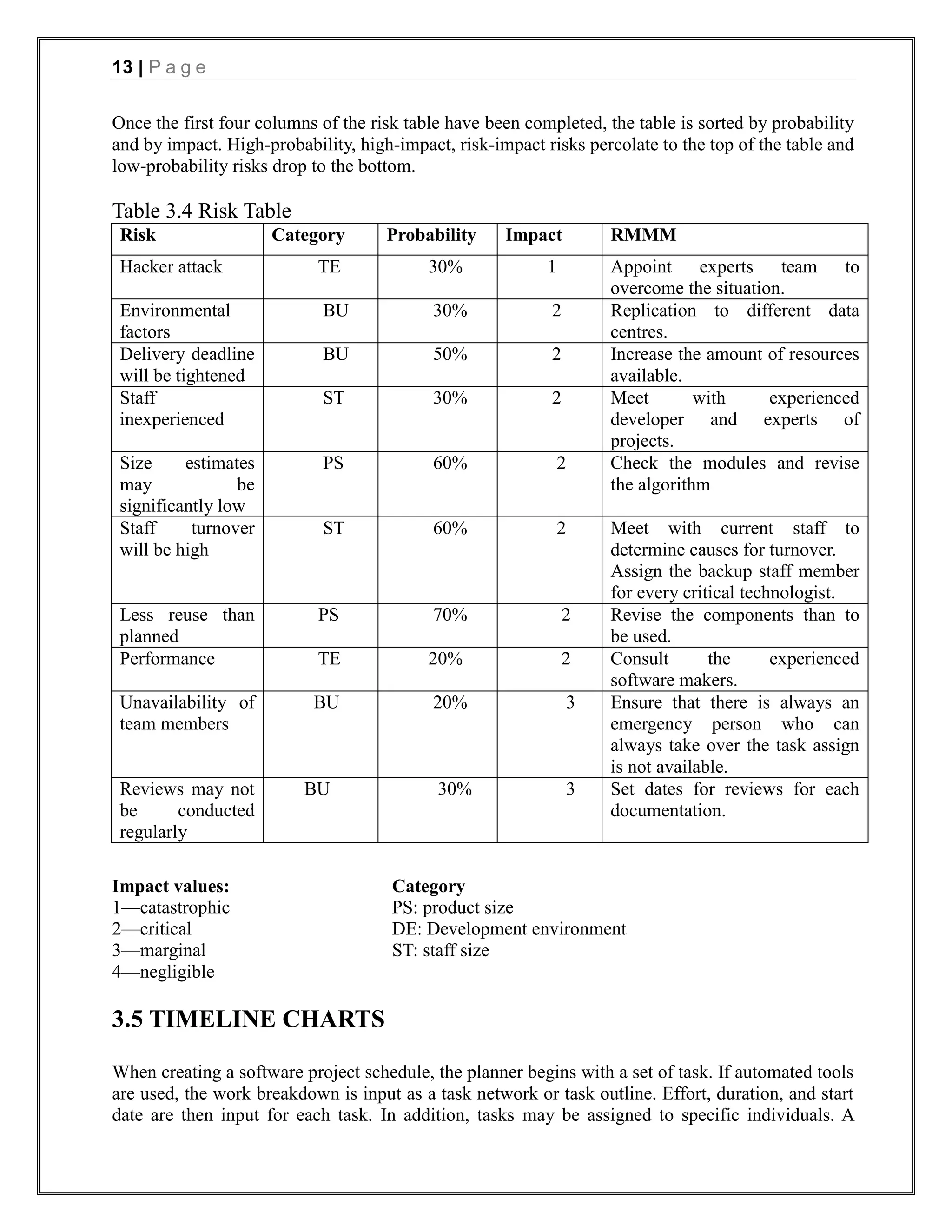
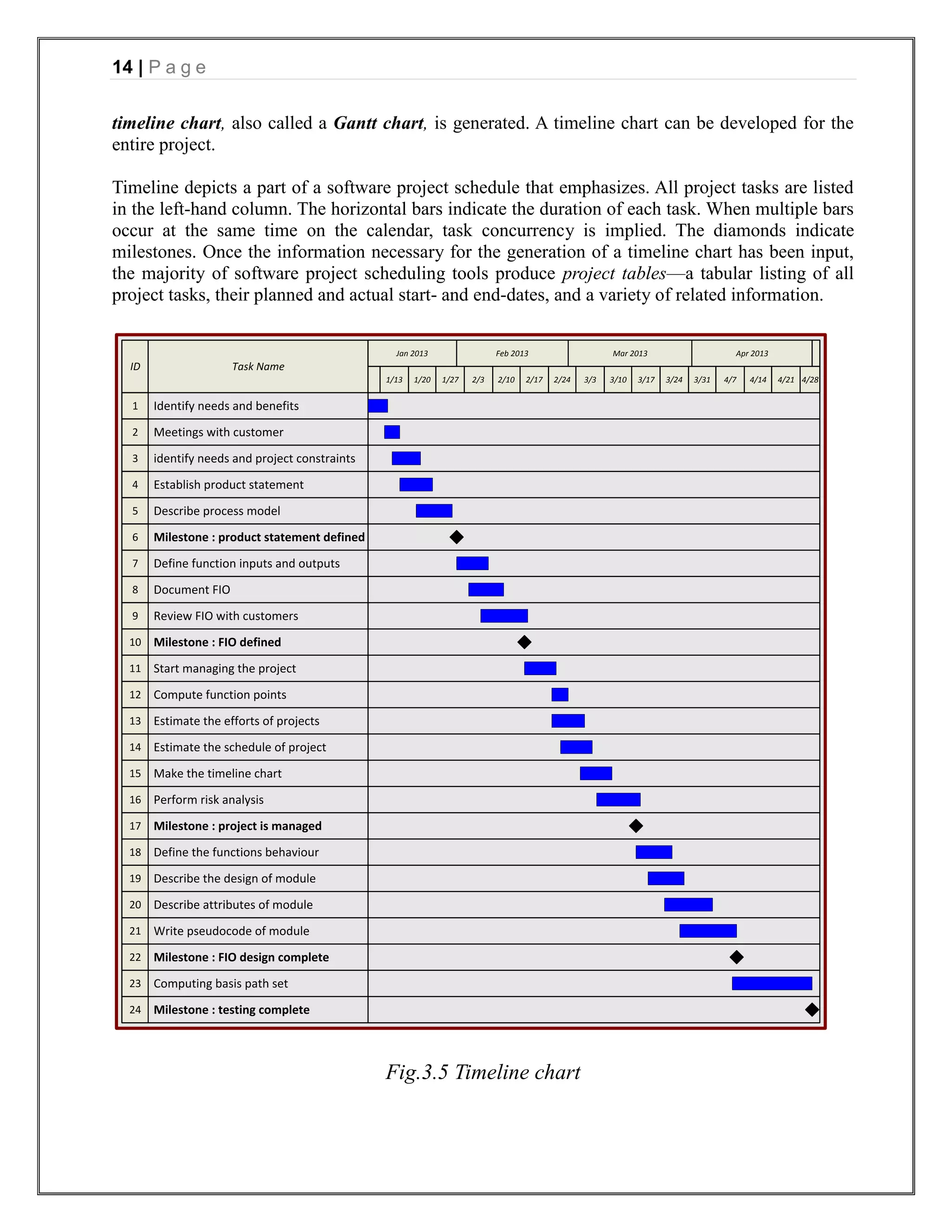
3.4 RISK TABLE
A table provides a project manager with a simple technique for risk production. A risk table is
sorted by probability and impact to rank risks. A project team begins by listing all risks in the 1st
column of the table. This can accomplished with the help of the risk item checklist referenced.
Each risk is categorized in the 2nd column. The probability of occurrence of each risk is entered in
the next column of the table.
Next, the impact of each risk is assessed. Each risk component is assessed using the
characterization presented and an impact category is determine. The categories for each of the four
risk components-performance, support, cost and schedule-are averaged to determine an overall
impact value.](https://image.slidesharecdn.com/onlinevotingsystemproject-130416093803-phpapp01/75/Online-voting-system-project-12-2048.jpg)