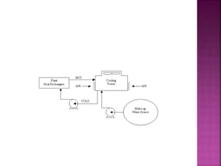
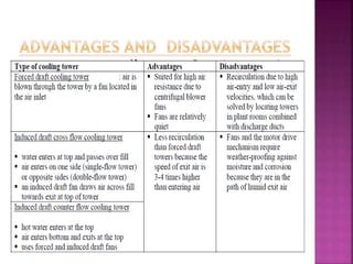
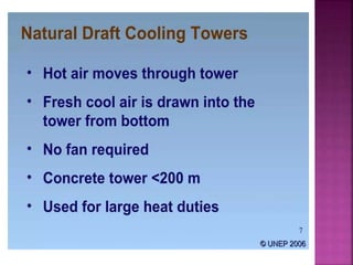
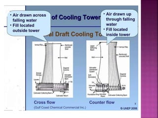
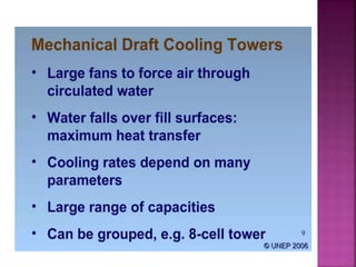
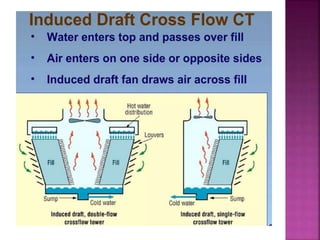
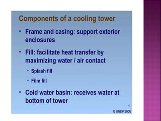
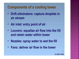
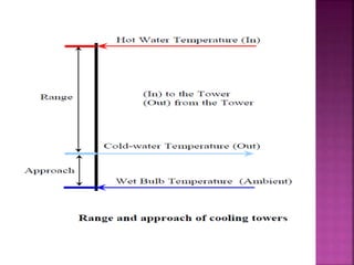
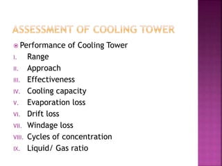
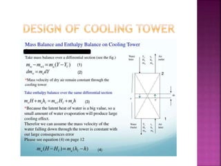
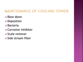
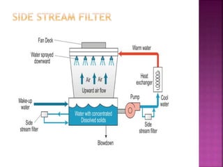
COOLING TOWER
BIJIT BISWAS
ASSISTANT PRODUCTION MANAGER
 Introduction
 Classification of Cooling Tower
 Components used in Cooling Tower to
manufacture
 Introducing to various terms related Cooling
Tower
 Assessment of Cooling Tower
 Psychometric Chart
 Design of Cooling Tower
 Maintenance of Cooling Tower
 Cooling towers are a very important part of many chemical
plants. The primary task of a cooling tower is to reject
heat into the atmosphere. They represent a relatively
inexpensive and dependable means of removing low-grade
heat from cooling water. The make-up water source is used
to replenish water lost to evaporation. Hot water from
heat exchangers is sent to the cooling tower. The water
exits the cooling tower and is sent back to the exchangers
or to other units for further codling. Typical closed loop
cooling tower system is shown in Figure
 Range :- This is the difference between the
cooling tower water inlet and outlet
temperature.
 Approach:- This is the difference between
the cooling tower outlet coldwater
temperature and ambient wet bulb
temperature.
 L(T1 – T2) = G(h2 – h1)
 L/G = (h2 – h1) / (T1 – T2)
 Where:
 L/G = liquid to gas mass flow ratio (kg/kg)
 T1 = hot water temperature (0oC)
 T2 = cold-water temperature (0oC)
 h2 = enthalpy of air-water vapor mixture at
exhaust wet-bulb temperature (same units as
above)
 h1 = enthalpy of air-water vapor mixture at inlet
wet-bulb temperature (same units as above)
 Frame and casing: Support exterior enclosures
 Fill: Facilitate heat transfer by maximizing water
/ air contact
 Cold water basin: Receives water at bottom of
tower
 Drift eliminators: Capture droplets in air stream
 Air inlet: Entry point of air
 Louvers: Equalize air flow into the fill and retain
water within tower
 Nozzles: Spray water to wet the fill
 Fans: Deliver air flow in the tower
 Measured parameters
I. Dry bulb temperature
II. Wet bulb temperature
III. Inlet water temperature
IV. Outlet water temperature
V. Exhaust air temperature
VI. Electrical reading of pump and fan motors
VII. Water flow rate
VIII. Air flow rate
 Performance of Cooling Tower
I. Range
II. Approach
III. Effectiveness
IV. Cooling capacity
V. Evaporation loss
VI. Drift loss
VII. Windage loss
VIII. Cycles of concentration
IX. Liquid/ Gas ratio
 OBJECTIVE OF THE MODEL (To analyze how well
an organization is positioned to achieve its
intended objective
 Usage
 Improve the performance of a company
 Examine the likely effects of future changes
within a company
 Align departments and processes during a merger
or acquisition
 Determine how best to implement a proposed
strategy
 Blow down
 Deposition
 Bacteria
 Corrosion inhibitor
 Scale remover
 Side stream filter
Ppt-Cooling-Tower.pptx

Ppt-Cooling-Tower.pptx

  • 1.
  • 2.
     Introduction  Classificationof Cooling Tower  Components used in Cooling Tower to manufacture  Introducing to various terms related Cooling Tower  Assessment of Cooling Tower  Psychometric Chart  Design of Cooling Tower  Maintenance of Cooling Tower
  • 3.
     Cooling towersare a very important part of many chemical plants. The primary task of a cooling tower is to reject heat into the atmosphere. They represent a relatively inexpensive and dependable means of removing low-grade heat from cooling water. The make-up water source is used to replenish water lost to evaporation. Hot water from heat exchangers is sent to the cooling tower. The water exits the cooling tower and is sent back to the exchangers or to other units for further codling. Typical closed loop cooling tower system is shown in Figure
  • 18.
     Range :-This is the difference between the cooling tower water inlet and outlet temperature.  Approach:- This is the difference between the cooling tower outlet coldwater temperature and ambient wet bulb temperature.
  • 19.
     L(T1 –T2) = G(h2 – h1)  L/G = (h2 – h1) / (T1 – T2)  Where:  L/G = liquid to gas mass flow ratio (kg/kg)  T1 = hot water temperature (0oC)  T2 = cold-water temperature (0oC)  h2 = enthalpy of air-water vapor mixture at exhaust wet-bulb temperature (same units as above)  h1 = enthalpy of air-water vapor mixture at inlet wet-bulb temperature (same units as above)
  • 20.
     Frame andcasing: Support exterior enclosures  Fill: Facilitate heat transfer by maximizing water / air contact  Cold water basin: Receives water at bottom of tower  Drift eliminators: Capture droplets in air stream  Air inlet: Entry point of air  Louvers: Equalize air flow into the fill and retain water within tower  Nozzles: Spray water to wet the fill  Fans: Deliver air flow in the tower
  • 21.
     Measured parameters I.Dry bulb temperature II. Wet bulb temperature III. Inlet water temperature IV. Outlet water temperature V. Exhaust air temperature VI. Electrical reading of pump and fan motors VII. Water flow rate VIII. Air flow rate
  • 22.
     Performance ofCooling Tower I. Range II. Approach III. Effectiveness IV. Cooling capacity V. Evaporation loss VI. Drift loss VII. Windage loss VIII. Cycles of concentration IX. Liquid/ Gas ratio
  • 25.
     OBJECTIVE OFTHE MODEL (To analyze how well an organization is positioned to achieve its intended objective  Usage  Improve the performance of a company  Examine the likely effects of future changes within a company  Align departments and processes during a merger or acquisition  Determine how best to implement a proposed strategy
  • 36.
     Blow down Deposition  Bacteria  Corrosion inhibitor  Scale remover  Side stream filter