
Recommended
More Related Content
Similar to pp05-1.ppt
Similar to pp05-1.ppt (20)
Recently uploaded
Recently uploaded (20)
pp05-1.ppt
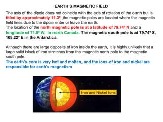
- 1. The axis of the dipole does not coincide with the axis of rotation of the earth but is titled by approximately 11.3º ,the magnetic poles are located where the magnetic field lines due to the dipole enter or leave the earth. The location of the north magnetic pole is at a latitude of 79.74º N and a longitude of 71.8º W, in north Canada. The magnetic south pole is at 79.74º S, 108.22º E in the Antarctica. Although there are large deposits of iron inside the earth, it is highly unlikely that a large solid block of iron stretches from the magnetic north pole to the magnetic south pole. The earth’s core is very hot and molten, and the ions of iron and nickel are responsible for earth’s magnetism EARTH’S MAGNETIC FIELD
- 2. Moon, which has no molten core, has no magnetic field, Venus has a slower rate of rotation, and a weaker magnetic field, while Jupiter, which has the fastest rotation rate among planets, has a fairly strong magnetic field. The variation of the earth’s magnetic field with position - Charged particles emitted by the sun flow towards the earth and beyond, in a stream called the solar wind. Their motion is affected by the earth’s magnetic field, and in turn, they affect the pattern of the earth’s magnetic field. The pattern of magnetic field near the poles is quite different from that in other regions of the earth.
- 3. The variation of earth’s magnetic field with time . There are short term variations taking place over centuries and long term variations taking place over a period of a million years. In a span of 240 years from 1580 to 1820 AD, the magnetic declination at London has been found to change by 3.5º, suggesting that the magnetic poles inside the earth change position with time. On the scale of a million years, the earth’s magnetic fields has been found to reverse its direction. Basalt contains iron, and basalt is emitted during volcanic activity. The little iron magnets inside it align themselves parallel to the magnetic field at that place as the basalt cools and solidifies. Geological studies of basalt containing such pieces of magnetised region have provided evidence for the change of direction of earth’s magnetic field.
- 4. Matter is made up of molecules and a molecule is made up of atoms A circulating electron in an atom has a magnetic moment. The resultant magnetic moment of an atom is the vector sum of magnetic moments of all electrons circulating nucleus. . The magnetic moments of all atoms in a bulk material are randomly oriented, so the net magnetic moment is zero. In a bulk material, these moments add up vectorially and they can give a net magnetic moment which is non-zero
- 5. Magnetisation M of a sample to be equal to its net magnetic moment per unit volume: Consider a long solenoid of n turns per unit length and carrying a current I. when the magnetic material is inserted into the solenoid, the material gets magnetised. B is the total magnetic field inside the material. B0 is the magnetic field due to the current carrying carrying solenoid. solenoid. Bm is the magnetic field due to the magnetisation of the material I is the intensity of magnetisation. H is the intensity of the total magnetic field
- 6. Intensity of magnetisation depends upon the nature of the material and the strength of the external magnetic field in which the material is magnetised. measure of magnisation (susceptibility of the material). B = μ H
- 7. Diamagnetism Diamagnetic substances are those which have tendency to move from stronger to the weaker part of the external magnetic field. In other words, unlike the way a magnet attracts metals like iron, it would repel a diamagnetic substance.
- 8. Diamagnetic substances are the ones in which resultant magnetic moment in an atom is zero. When magnetic field is applied, those electrons having orbital magnetic moment in the same direction slow down and those in the opposite direction speed up. Some diamagnetic materials are bismuth, copper, lead, silicon, nitrogen (at STP), water and sodium chloride. The most exotic diamagnetic materials are superconductors. These are metals, cooled to very low temperatures which exhibits both perfect conductivity and perfect diamagnetism
- 9. Paramagnetism Paramagnetic substances are those which get weakly magnetised when placed in an external magnetic field. They have tendency to move from a region of weak magnetic field to strong magnetic field, i.e., they get weakly attracted to a magnet The individual atoms (or ions or molecules) of a paramagnetic material possess a permanent magnetic dipole moment of their own. On account of the ceaseless random thermal motion of the atoms, no net magnetisation
- 10. Some paramagnetic materials are aluminium, sodium, calcium, oxygen (at STP) and copper chloride. Magnetisation of a paramagnetic material is inversely proportional to the absolute temperature T, This is known as Curie’s law, after its discoverer Pieree Curie
- 11. Ferromagnetism Ferromagnetic substances are those which gets strongly magnetised when placed in an external magnetic field. They have strong tendency to move from a region of weak magnetic field to strong magnetic field, i.e., they get strongly attracted to a magnet. The individual atoms (or ions or molecules) in a ferromagnetic material possess a dipole moment as in a paramagnetic material They interact with one another in such a way that they spontaneously align themselves in a common direction over a macroscopic volume called domain Typical domain size is 1mm and the domain contains about atoms
- 12. When we apply an external magnetic field B0, the domains orient themselves in the direction of B0 and simultaneously the domain oriented in the direction of B0 grow in size Thus, in a ferromagnetic material the field lines are highly concentrated. In some ferromagnetic materials the magnetisation persists. Such materials are called hard magnetic materials or hard ferromagnets. Alnico, an alloy of iron, aluminium, nickel, cobalt and copper, is one such material. The naturally occurring lodestone. Such materials form permanent magnets There is a class of ferromagnetic materials in which the magnetisation disappears on removal of the external field. Soft iron is one such material. such materials are called soft ferromagnetic materials. iron, cobalt, nickel, gadolinium, etc. The relative magnetic permeability is >1000! The ferromagnetic property depends on temperature The temperature of transition from ferromagnetic to paramagnetism is called the Curie temperature Tc.
- 13. For a given value of H, B is not unique but depends on previous history of the sample. This phenomenon is called hysterisis. The word hysterisis means lagging behind.
- 14. PERMANENT MAGNETS AND ELECTROMAGNETS Substances which at room temperature retain their ferromagnetic property for a long period of time are called permanent magnets. An efficient way to make a permanent magnet is to place a ferromagnetic rod in a solenoid and pass a current. The magnetic field of the solenoid magnetises the rod. The material for permanent magnets should have high retentivity so that the magnet is strong and high coercivity , so that the magnetisation is not erased by stray magnetic fields , have a high permeability. Suitable materials for permanent magnets are steel, alnico, cobalt steel and ticonal. Materialls which have high permeability and low retentivity. Soft iron is a suitable material for electromagnets. On placing a soft iron rod in a solenoid and passing a current, increases the magnetism of the solenoid. When we switch off the solenoid current, the magnetism is effectively switched off since the soft iron core has a low retentivity. The material goes through an ac cycle of magnetisation for a long period, have narrow hysteresis curve, have a high resistivity to lower eddy current losses Electromagnets are used in electric bells, loudspeakers and telephone diaphragms. Giant electromagnets are used in cranes
- 16. LENZ’S LAW AND CONSERVATION OF ENERGY In 1834, German physicist Heinrich Friedrich Lenz (1804-1865) deduced a rule, known as Lenz’s law The polarity of induced emf is such that it tends to produce a current which opposes the change in magnetic flux that produced it. As the North-pole of the bar magnet moves towards the coil, the magnetic flux through the coil increases. Hence current is induced in the coil in such a direction that it opposes the increase in flux , hence current in the coil is in a counter-clockwise direction , and magnetic moment associated with this current has North polarity towards the North-pole of the approaching magnet. Similarly, if the Northpole of the magnet is being withdrawn from the coil, the magnetic flux through the coil will decrease. To counter this decrease in magnetic flux, the induced current in the coil flows in clockwise direction and its Southpole faces the receding North-pole of the bar magnet. This would result in an attractive force which opposes the motion of the magnet and the corresponding decrease in flux.
- 17. Conservation of energy Lenz’s law , established on the basis of the law of conservation According to Lenz’s law, when a magnet is moved either towards or away from a coil, the induced current produced opposes its motion. As a result, there will always be a resisting force on the moving magnet. Work has to be done by some external agency to move the magnet against this resisting force. Here the mechanical energy of the moving magnet is converted into the electrical energy
- 18. On the contrary to Lenz’s law, when we push the magnet towards the coil, the induced current helps the movement of the magnet towards the coil. Then the magnet starts moving towards the coil without any expense of energy. Fleming’s right hand rule When a conductor moves in a magnetic field, the direction of motion of the conductor, the field and the induced current are given by Fleming’s right hand rule The thumb, index finger and middle finger of right hand are stretched out in mutually perpendicular directions . If the index finger points the direction of the magnetic field and the thumb indicates the direction of motion of the conductor, then the middle finger will indicate the direction of the induced current.
- 19. MOTIONAL ELECTROMOTIVE FORCE Let us consider a straight conductor moving in a uniform and time independent magnetic field. PQRS in which the conductor PQ is free to move. The rod PQ is moved towards the left with a constant velocity v . PQRS forms a closed circuit enclosing an area that changes as PQ moves. It is placed in a uniform magnetic field B which is perpendicular to the plane of this system. If the length RQ = x and RS = l, the magnetic flux ΦB enclosed by the loop PQRS Since x is changing with time, the rate of change of flux ΦB will induce an emf given by: speed of the conductor PQ. The induced emf Blv is called motional emf. Thus, we are able to produce induced emf by moving a conductor instead of varying the magnetic field, that is, by changing the magnetic flux enclosed by the circuit. dx/dt = –v
- 20. Lorentz force acting on the free charge carriers of conductor PQ. Consider any arbitrary charge q in the conductor PQ. When the rod moves with speed v, the charge will also be moving with speed v in the magnetic field B. The Lorentz force on this charge is qvB in magnitude, and its direction is towards Q. All charges experience the same force, in magnitude and direction, irrespective of their position in the rod PQ. The work done in moving the charge from P to Q is, Since emf is the work done per unit charge, An emf is induced when a conductor is stationary and the magnetic field is changing time-varying magnetic field generates an electric field. F = q (E + v × B) = qE
- 21. Motional emf from Faraday’s law and Energy conservation Let us consider a rectangular conducting loop of width l in a uniform magnetic field which is perpendicular to the plane of the loop and is directed inwards. A part of the loop is in the magnetic field while the remaining part is outside the field When the loop is pulled with a constant velocity to the right, the area of the portion of the loop within the magnetic field will decrease. Thus, the flux linked with the loop will also decrease. According to Faraday’s law, an electric current is induced in the loop which flows in a direction so as to oppose the pull of the loop. Let x be the length of the loop which is still within the magnetic field, then its area is lx . The magnetic flux linked with the loop is:
- 22. As this magnetic flux decreases due to the movement of the loop, the magnitude of the induced emf is given by
- 23. This emf is known as motional emf since it is produced due to the movement of the loop in the magnetic field. From Lenz’s law, it is found that the induced current flows in clockwise direction. If R is the resistance of the loop, then the induced current is given by Energy conservation In order to move the loop with a constant velocity , a constant force that is equal and opposite to the magnetic force, must be applied. Therefore, mechanical work is done to move the loop. Then the rate of doing work or power is The magnetic force acting on the loop due to its movement in the magnetic field.
- 24. Thus the mechanical work done in moving the loop appears as thermal energy in the loop. When the induced current flows in the loop, Joule heating takes place. The rate at which thermal energy is dissipated in the loop or power dissipated is
- 25. ENERGY CONSIDERATION: A QUANTITATIVE STUDY Let r be the resistance of movable arm PQ of the rectangular conductor current I in the loop is, On account of the presence of the magnetic field, there will be a force on the arm PQ. This force I (l × B), is directed outwards in the direction opposite to the velocity of the rod. The magnitude of this force is, required to do this is, Power is dissipated as Joule heat
- 26. EDDY CURRENTS Electric currents induced in well defined paths in conductors like circular loops. Even when bulk pieces of conductors are subjected to changing magnetic flux, induced currents are produced in them. However, their flow patterns resemble swirling eddies in water. This effect was discovered by physicist Foucault (1819-1868) and these currents are called eddy Currents.(Foucault current) A copper plate is allowed to swing like a simple pendulum between the pole pieces of a strong magnet. It is found that the motion is damped and in a little while the plate comes to a halt in the magnetic field. Magnetic flux associated with the plate keeps on changing as the plate moves in and out of the region between magnetic poles. The flux change induces eddy currents in the plate. Directions of eddy currents are opposite when the plate swings into the region between the poles and when it swings out of the region. If rectangular slots are made in the copper plate , area available to the flow of eddy currents is less. Thus, the pendulum plate with holes or slots reduces electromagnetic damping and the plate more freely.
- 27. In reducing eddy currents in the metallic cores of transformers, electric motors and other such devices in which a coil is to be wound over metallic core. Eddy currents are undesirable since they heat up the core and dissipate electrical energy in the form of heat. Eddy currents are minimised by using laminations of metal to make a metal core. The laminations are separated by an insulating material like lacquer. The plane of the laminations must be arranged parallel to the magnetic field, so that they cut across the eddy current paths. This arrangement reduces the strength of the eddy currents. Since the dissipation of electrical energy into heat depends on the square of the strength of electric current, heat loss is substantially reduced Eddy current used in applications like: (i) Magnetic braking in trains: Strong electromagnets are situated above the rails in some electrically powered trains. When the electromagnets are activated, the eddy currents induced in the rails oppose the motion of the train. As there are no mechanical linkages, the braking effect is smooth. (ii) Electromagnetic damping: Certain galvanometers have a fixed core made of nonmagnetic metallic material. When the coil oscillates, the eddy currents generated in the core oppose the motion and bring the coil to rest quickly
- 28. (iii) Induction furnace: Induction furnace can be used to produce high temperatures and can be utilised to prepare alloys, by melting the constituent metals. A high frequency alternating current is passed through a coil which surrounds the metals to be melted. The eddy currents generated in the metals produce high temperatures sufficient to melt it. (iv) Electric power meters: The shiny metal disc in the electric power meter (analogue type) rotates due to the eddy currents. Electric currents are induced in the disc by magnetic fields produced by sinusoidally varying currents in a coil. Induction stove Induction stove is used to cook the food quickly and safely with less energy consumption. Below the cooking zone, there is a wound coil of insulated wire. The cooking pan made of suitable material, is placed over the cooking zone. When the stove is switched on, an alternating current flowing in the coil produces high frequency alternating magnetic field which induces very strong eddy currents in the cooking pan. The eddy currents in the pan produce so much of heat due to Joule heating which is used to cook the food
- 29. INDUCTANCE Inductor is a device used to store energy in a magnetic field when an electric current flows through it. The typical examples are coils, solenoids and toroids Inductance is the property of inductors to generate emf due to the change in current flowing through that circuit An electric current flowing through a coil will set up a magnetic field around it. Therefore, the magnetic flux of the magnetic field is linked with that coil itself. If this flux is changed by changing the current, an emf is induced in that same coil . This phenomenon is known as self-induction. The emf induced is called self-induced emf.
- 30. For a closely wound coil of N turns Self-inductance or simply inductance of a coil is defined as the flux linkage of the coil when 1A current flows through it. When the current i changes with time, an emf is induced in it. From Faraday’s law of electromagnetic induction, this self-induced emf is given by Inductance of a coil is also defined as the opposing emf induced in the coil when the rate of change of current through the coil is 1 A s−1. Unit of inductance Inductance is a scalar quantity Its dimension is
- 31. The inductance of the coil is said to be one henry if a current of 1 A produces unit flux linkage in the coil. Therefore, the inductance of the coil is one henry if a current changing at the rate of 1 A s−1 induces an opposing emf of 1 V in it. The inductance plays the same role in a circuit as mass and moment of inertia play in mechanical motion. When a circuit is switched on, the increasing current induces an emf which opposes the growth of current in a circuit . Likewise, when circuit is broken, the decreasing current induces an emf in the reverse direction. This emf now opposes the decay of current Thus, inductance of the coil opposes any change in current and tries to maintain the original state.
- 32. Self-inductance of a long solenoid Consider a long solenoid of length l and cross-sectional area A. Let n be the number of turns per unit length (or turn density) of the solenoid. When an electric current is passed through the solenoid, a magnetic field is produced by it which is almost uniform and is directed along the axis of the solenold
- 33. Energy stored in an inductor Whenever a current is established in the circuit, the inductance opposes the growth of the current. In order to establish a current in the circuit, work is done against this opposition by some external agency. This work done is stored as magnetic potential energy. The induced emf at any instant t is ε Let dW be work done in moving a charge dq in a time dt against the opposition, Hence the total work done in establishing the current i is This work done is stored as magnetic potential energy. The energy density is the energy stored per unit volume
- 34. Mutual inductance When an electric current passing through a coil changes with time, an emf is induced in the neighbouring coil. This phenomenon is known as mutual induction and the emf is called mutually induced emf. The mutual inductance M21 is defined as the flux linkage of the coil 2 when 1A current flows through coil 1.
- 35. When the current i1 changes with time, an emf ε2 is induced in coil 2. Mutual inductance M21 is also defined as the opposing emf induced in the coil 2 when the rate of change of current through the coil 1 is 1A/s. Similarly, Unit of mutual-inductance The mutual inductance between two coils is said to be one henry if a current of 1A in coil 1 produces unit flux linkage in coil 2. The mutual inductance between two coils is one henry if a current changing at the rate of 1A/s in coil 1 induces an opposing emf of 1V in coil 2.
- 36. Mutual inductance between two long co-axial solenoids Consider two long co-axial solenoids each of length l. The radius of the inner solenoid S1 by r1 , number of turns per unit length by n1. The radius of the outer solenoid S2 are r2 and n2, respectively. Let N1 and N2 be the total number of turns of coils S1 and S2, respectively. When a current I2 is set up through S2, it in turn sets up a magnetic flux through S1. Let us denote it by Φ1. The corresponding flux linkage with solenoid S1 is
- 37. A current I1 is passed through the solenoid S1 and the flux linkage with coil S2 is, The flux due to the current I1 in S1 can be assumed to be confined solely inside S1 since the solenoids are very long. Thus, flux linkage with solenoid S2 is If a medium of relative permeability μr had been present, the mutual inductance would be The mutual inductance of a pair of coils, solenoids, etc., depends on their separation as well as their relative orientation.
- 38. emf is induced in coil C1 wherever there was any change in current through coil C2. Let Φ1 be the flux through coil C1 (say of N1 turns) when current in coil C2 is I2. The magnitude of the induced emf depends upon the rate of change of current and mutual inductance of the two coils.