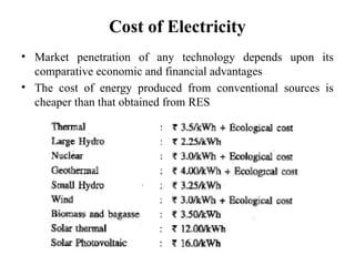
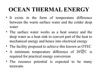
PX7301 Power Electronics for
Renewable Energy Systems
SYLLABUS
• UNIT I INTRODUCTION
• Environmental aspects of electric energy conversion: impacts
of renewable energy generation on environment (Cost-GHG
Emission) - Qualitative study of different renewable energy
resources Ocean, Biomass, Hydrogen energy systems:
Operating principles and Characteristics of: Solar PV, Fuel
cells, Wind electrical systems-control strategy, operating area
• UNIT II ELECTRICAL MACHINES FOR RENEWABLE
ENERGY CONVERSION
• Review of reference theory fundamentals - principle of
operation and analysis: IG, PMSG, SCIG and DFIG.
• UNIT III POWER CONVERTERS
• Solar: Block diagram of solar photo voltaic system: Line
commutated converters (Inversion mode) - Boost and Buck-boost
converters - selection of inverter, battery sizing, array sizing. Wind:
three phase AC voltage controllers - AC-DC-AC converters:
Uncontrolled rectifiers, PWM Inverters, Grid Interactive Inverters -
Matrix converters
• UNIT IV ANALYSIS OF WIND AND PV SYSTEMS
• Stand alone operation of fixed and variable speed wind energy
conversion systems and solar system - Grid connection Issues -
Grid integrated PMSG and SCIG Based WECS - Grid Integrated
solar system.
• UNIT V HYBRID RENEWABLE ENERGY SYSTEMS
• Need for Hybrid Systems- Range and type of Hybrid systems- Case
studies of Wind-PV-Maximum Power Point Tracking (MPPT).
REFERENCES:
1. S.N. Bhadra, D. Kastha, & S. Banerjee “Wind Electrical Systems”,
Oxford University Press, 2009
2. Rashid .M. H “Power Electronics Hand book”, Academic Press,
2001.
3. Rai. G.D, “Non conventional energy sources”, Khanna publishers,
1993.
4. Rai. G.D,” Solar energy utilization”, Khanna publishers, 1993.
5. Gray, L. Johnson, “Wind energy system”, Prentice hall inc, 1995.
6. Non-conventional Energy sources, B.H.Khan, Tata McGraw-hill
Publishing Company, New Delhi.
7. D.P.Kothari, et al, “Renewable Energy Sources and Emerging
Technologies”, Prentice-Hall of India Pvt. Ltd., Second Edition
Environmental Aspects of Electric Energy
Generation
I. Thermal Power Plants
• Atmospheric Pollution:
Major pollutants: SO2, NOX, CO and CO2,
Hydrocarbons, fly ash and suspended particulates
• Oxides of Sulphur (SO2)
– causes respiratory ailments (20 mg/m3
) and
constitutes danger to life (400 mg/m3
)
– In atmosphere it is further oxidized to H2SO4 and falls
down on the earth as acid rain (injurious to plants and
damage to buildings)
• Oxides of Nitrogen (NOX)
– It includes NO, NO2 and N2O
– NO2 major pollutant, highly injurious; if inhaled in
concentration of 150-200 ppm
– NO2 damage respiratory tissues, cause pneumonia
• Oxides of Carbon (CO and CO2)
– CO is toxic gas, affects human metabolism, if released to
atmosphere, it gets converted to CO2
– CO2 in high concentration causes global warming
• Hydrocarbons
– Damages atmospheric ozone layer
• PARTICULATES (FLY ASH)
– Fine particles of carbon, ash and other inert material with
size > 1μm
– Emitted from chimney in the form of fly ash
– Particulates with level 300 μg/m3
cause poor visibility,
lungs inflammation and bronchitis
• Steam cycle efficiency even after improvement is
only 40%
• Unused 60% heat in steam at the cycle end is
dissipated to the atmosphere
II. Hydroelectric Power Plants
• Terrestrial effects
– Destruction of forest and damage to flora and fauna do take
place due to submergence of vast land in artificial lakes
– Depletion of forest areas creates a highly negative effect on
biological diversity
• Wild life
– Reduction in vegetation cover at the construction site
disturbs wild life habitat
– Blasting operations, movement of heavy machines, noise
and dust produced during construction, drive away wild
animals
– The risk of fire endangers jungle conservation
• Aquatic life
─ Construction work and movement of heavy vehicles on water
course, contamination of water by accidental spilling of oil, all
lower the quality of water for fish breeding
─ Proper personnel carrying fishing activities with explosives also
cause damage to aquatic life
• Social life
─ Such projects uproot the local population who is forced to shirt
to new environment
• Submergence of cultural heritage
─ Reservoirs spread over a large area threaten submergence of
ancient cultural heritage, temples, monuments and historical
structures
─ It creates discontentment in local people charged with religious
sentiments
• Health concern
– Hospitals with medical staff, trained health workers, medical
equipment and medicines become a mandatory requirement
in the project area itself
– Local people are also benefited by such clinical facilities
• Economic aspect
– Effort is made to employ local people as unskilled and semi-
skilled workforce
– The displaced, compensated people are given the first
priority to work
– A consistent, fair and equitable employment policy is
adopted
– Local farmers are benefited by new road networks and can
thus diversify the sale of their farm products
• Physical effects
Land degradation
The construction of a project entails mass failure,
landslides and slope failures on steep gradients
Soil erosion and heavy precipitation accelerate these
processes
Quarrying, earth excavation and tunnel-muck dumping
become notable sites of land degradation
Water pollution
Garbage dumping, sewage disposal and septic tanks are
built away from the water courses to obviate
contamination by seepage or direct runoff
III. Nuclear Power Plants
• Radioactive pollution – The areas of possible
radioactive releases by NPPs are:
– Radiations during uranium mining
– Processing of uranium ore as fuel for nuclear
reactors
– Operation of nuclear reactors for power generation
– Accidental radiological hazards
– Contamination from nuclear waste
• Disposal of nuclear waste
– Major wastes generated in a nuclear fuel cycle are
‘low-active wastes’ handled like other wastes and
dispersed
– ‘Medium-level wastes’ do not create any problems
and can be disposed with the techniques of dilution
and decay
– Difficulty arises with ‘high-level radioactive
wastes’ which require special technology to handle
for a long-term solution to their disposal
Impact of Renewable Energy Generation
on Environment
1. Solar energy
– Available in abundance, converted into usable
form through solar thermal, solar PV and solar
architecture
– Main problem associated with tapping solar
energy is the requirement to install large solar
collectors
• High cost in populated areas
• Heat transfer fluids (glycol nitrates, sulphates, CFCs
and aromatic alcohols) pose health hazard due to
careless disposal
• Solar PV modules pose disposal problems due to the
presence of arsenic and cadmium
• Battery banks with inverters, back-up diesel generator
contains several pollutants
• Hazards to eyesight from solar reflectors
• Large scale use of solar thermal collectors and roof top
PV in densely populated cities limits the exposure of
people to daylight due to changes in albedo
2. Wind energy – No water and air pollution
• Requires large land area, in a forest area needs
cutting of trees leading to degradation of
environment
• Visual intrusion of wind turbines on the existing
landscape gives negative public response
• Degrade environment by noise pollution
• Interfere with television signals through reflection
• Hazards for birds, especially those in a migration
route
3. Biomass energy - Supports soil fertilization,
checks water runoff and stops desertification
• Combustion produces air pollution
• Accelerates soil erosion and nutrient loss
• Energy-crop plantation on a large scale is water
consuming with increased use of pesticides and
fertilizers, causes water pollution and flooding
• Domestic use of biomass in rural areas creates
air pollution, a health-hazard for women and
children
4. Geothermal energy – steam and water contain non-
condensable gases CO2, CH4, NH3 and H2S besides several
toxic chemicals
• Gases containing H2S are oxidised to SO2 and H2SO4 and
drop down as acid rain
• Chemicals like sulphates, chlorides, and carbonates of lead,
boron and arsenic pollute soil and water
• Discharge of waste hot water infects rivers, drinking water,
farming and fisheries
• Noise pollution caused by exhausts, blow downs and
centrifugal separation is a health hazard
• Large-scale withdrawal of underground fluids may trigger
ground subsidence, causing damage to surface structures
5. Ocean Thermal Energy Conversion (OTEC) –
convert thermal energy of ocean water, acquired from
solar radiations, into electrical energy
• An OTEC plant displaces nearly 4 m3
water per MW
generation, massive flow disturbs thermal balance,
changes salinity gradient and turbidity, creates adverse
impacts on marine environment
• Mining of warm and cold water near the surface
triggers thermal effects, forcing mortality among coral
and fishes
• Ammonia is used as working fluid in closed cycle
OTEC system; its leakage may cause great damage to
the ocean eco system
Greenhouse Effect
• A greenhouse is an enclosure having transparent glass panes o
sheets
• It is transparent for incoming visible solar radiation and
largely opaque for outgoing reflected infrared radiation from
earth’s surface, thus preventing the exit of heat
• The CO2 envelope present around the globe in the atmosphere
behaves similar to this and forms a big global greenhouse
• this tends to prevent the escape of heat from the earth, which
leads to Global warming, known as Greenhouse effect
• It is due to this effect that the earth maintains an
average surface temperature of 15C (hospitable to
life)
• In the absence of this layer, the earth would be frozen
planet at about -25C
• However any further increase in the concentration of
CO2 will upset the temperature balance and would
cause further warming of globe
• Apart from CO2, other harmful gases include
methane, nitrous oxide, hydroflourocarbons, sulphur
hexafloride and water vapour (Greenhouse gases)
Consequences of Global Warming
• It is cause mainly due to the emission of excessive CO2 due to
burning of fossil fuels, wood, etc.
• This trend is leading to melting of polar snowcaps (90% world’s ice)
• Melting of polar snowcaps would in turn increase the level of
oceans (redefine ocean boundaries), inundating low-lying areas and
smaller islands
• During the last 100 years, the earth’s temperature has increased
about half a degree Celsius and sea levels have risen 6 to 8 inches
• More frequent and severe heat waves, more intense tropical
cyclones, change in rainfall patterns, melting of ice and glaciers at
mountains causing floods followed by decline of water supplies and
an increased incidence of vector-borne deceases like malaria
Cost of Electricity
• Market penetration of any technology depends upon its
comparative economic and financial advantages
• The cost of energy produced from conventional sources is
cheaper than that obtained from RES
• Comparative study of electricity production
cost from RES and fossil fuel are quite
matching except solar thermal and solar PV
• However, Kyoto Protocol covers this aspect
and called upon the signatories to take
remedial steps
• With growing population and desire for better
standard of living, the cost of electricity should
be affordable ensuring concurrently, a non-
polluting environment
GHG Emissions
• It is evident from table that the renewable energy sources
make little contribution to CO2 emissions
• Ecological Cost
– covers all expenses incurred to correct the environmental damage
occurred during production and disposal of waste from exhaustible
energy sources, also termed as ‘Green Accounting’
Ocean Energy
• Tides are produced by the gravitational attraction of the moon and
sun acting upon the rotating earth
• The moon exerts a larger gravitational force, as it is closer than sun
• Surface water is pulled away from the earth on the side facing the
moon, and at the same time the solid earth is pulled away from the
water on the opposite side
• Thus the ocean height increases at both the near and far sides of the
earth as shown in Fig.
• The highest level of tidal water is known as flood tide or high
tide
• The lowest level is known as low tide or ebb
• The level difference between the high and low tide is known
as tidal range
• The tidal range varies greatly with location, only sites with
large tidal ranges (about 5m or more) are considered suitable
for power generation
Origin and Nature of Tidal Energy
• When the sun, earth and moon are aligned in
conjunction, the lunar and solar tides are in phase,
producing net tides of maximum range
• These are spring tides occurring twice per lunar month
at time of both full and new moon
• When sun-earth and moon-earth directions are
perpendicular (quadrature), the solar and lunar tides are
out of phase producing net tides of minimum range.
• These are neap tides that again occur twice per month at
times of half moon (1st
and 3rd
quarter cycle of moon)
OCEAN THERMAL ENERGY
• It exists in the form of temperature difference
between the warm surface water and the colder deep
water
• The surface water works as a heat source and the
deep water as a heat sink to convert part of the heat to
mechanical energy and hence into electrical energy
• The facility proposed to achieve this known as OTEC
• A minimum temperature difference of 20C is
required for practical energy conversion
• The resource potential is expected to be many
terawatts
• The main advantages of OTEC are:
i. The resource supplies steady power without
fluctuations and independent of vagaries of weather
ii. The availability hardly varies from season to season
iii. At a suitable site the resource is essentially limited
only by the size of the system
iv. The required machinery are simple
v. It also has the ability to create some useful by-products
such as desalinated water and nutrients for mariculture
• The major disadvantages are:
i. Low efficiency and
ii. High installation cost
Origin and Characteristics of Resource
• The origin of OTEC may be traced to solar
radiation on ocean surface
• In fact the ocean is the world’s largest solar
collector
• Therefore, the resource is a virtually
inexhaustible source of energy
• Absorption of solar energy in water takes
place according to Lambert’s law of absorption
OTEC Technology
• OTEC plants can operate on two cycles:
–Open cycle (Claude cycle) and
–Closed cycle (Anderson cycle)
Open Cycle
• In an open cycle plant, warm water from the ocean
surface is flash evaporated under partial vacuum
• Low-pressure steam obtained is separated and passed
through a turbine to extract energy
• The exhaust of the turbine is condensed in a direct
contact condenser
• Cold water drawn from a depth of about 1000m is
used as cooling water
• The resulting mixture of used cooling water and
condensate is disposed in the sea
• If a surface condenser is used, the condensate could
be used as desalinated water
Closed Cycle
• In a closed cycle plant, warm surface water is used to evaporate a
low-boiling-point working fluid (ammonia, freon or propane)
• The vapour flows through the turbine and is then cooled and
condensed by cold water pumped from the ocean depths
• Because of the low quality of the heat, large surface areas of heat
exchangers required and a large amount of water needs to be
circulated
• The operating pressures of the working fluid at the
boiler/evaporator and condenser are much higher and its specific
volume is much lower
• It results in turbine that is smaller in size and hence less costly as
compared to that in an open cycle system
• Both open and closed cycle plants can be mounted on a ship or
built on shore
• Although both systems are being explored, the closed-cycle system
appears to be more promising in the near future
• The deposition and growth of micro organisms inside the pipes
of evaporators and condenser heat exchangers is known as
biofouling
• It reduces the heat-transfer efficiency and thereby lowers the
performance
• It is one of the major problems in OTEC design
• Among the methods being tried to keep the fouling under
control are mechanical cleaning and the chemical cleaning
(chlorination) by additives to the water
• Use of biocides to prevent fouling is cited as a source of
pollution
Environmental Impacts
BIOMASS ENERGY
• The energy obtained from the biomass is known as biomass
energy
• Animals feed on plants, and plants grow through the
photosynthesis process using solar energy
• Thus the photosynthesis process is primarily responsible for
generation of biomass energy
• A small portion of solar radiation is captured and stored in
plants during the photosynthesis process
• Therefore, it is an indirect form of solar energy
• The average efficiency of photosynthetic conversion of solar
energy into biomass energy is estimated to be 0.5-1 %
H2O + CO2 CH20 + O2
solar energy
Usable forms of Biomass
1. Fuel wood
2. Charcoal
3. Fuel pellets and Briquettes
4. Bio-diesel
5. Bio-ethanol
6. Biogas
7. Producer gas
Biomass Resources
• Biomass resources for energy production are widely
available in forest areas rural farms, urban refuse and
organic waste from agro-industries .
• Biomass classification:
Biomass Conversion Technologies
• The energy conversion technologies may be
grouped into four basic types:
i. Physical methods
ii. Incineration (direct combustion)
iii. Thermochemical method
iv. Biochemical method
1. Physical Method
• The simplest form of physical conversion of biomass is through
compression of combustible material
• Its density is increased by reducing the volume by compression
through the process called briquetting and pelletization
i. Briquetting:
• Biomass briquettes are made from woody matter (agricultural
waste, saw dust, etc.) are a replacement for fossil fuels and can
be used to heat boilers in manufacturing plants
• Burning a wood briquette is far more efficient than burning
firewood
• The moisture content of briquette can be as low as 4%, whereas
for green firewood, it may be as high as 65%
ii. Pelletization:
• It is a process in which waste wood is pulverized, dried and
forced under pressure through an extrusion device
• The extracted mass is in the form of pellets, facilitating its
use in steam power plants and gasification system
• Pelletization reduces the moisture to about 7 to 10 % and
increases the heat value of the biomass
2. Incineration
• It means direct combustion of biomass for
immediate useful heat
• The heat and/or steam produced are either
used to generate electricity or provide the
heat for industrial process, space heating and
cooking
3. Thermochemical Method
• The basic thermochemical process to convert to convert biomass into a
more valuable and/or convenient product is known as Pyrolysis
• Biomass is heated either in absence of oxygen or by partial combustion
of some of the biomass in restricted air or oxygen supply
• Pyrolysis can process all forms of organic materials rubber and plastics,
which cannot be handled by other methods
• The products are three types of fuels – usually, a gas mixture, an oil-like
liquid and nearly pure carbon char
• High temperature pyrolysis maximises the gaseous product, the process
is known as gasification
• Low temperature pyrolysis maximises char output, the process is known
as carbonization
• A liquid product is obtained through catalytic liquefaction process
(relatively low temperature, high pressure thermochemical conversion
of wet biomass)
4. Biochemical Method
• The process makes use of metabolic action of microbial
organisms on biomass to produce liquid and gaseous fuels.
• Two major biochemical processes are:
a) Ethanol Fermentation
― Alcoholic fermentation is the decomposition in the absence
of air of simple hexose sugars in aqueous solution by the
action of an enzyme present in catalyst, in acidic conditions
― C6H12O6 2C2H5OH + 2CO2
― The products are ethanol and carbon dioxide
32 C
Fermentation
b) Anaerobic Fermentation (Anaerobic Digestion)
― This process converts decaying wet biomass and animal wastes
into biogas through the decomposition process by the action of
anaerobic bacteria
― Carbon present in biomass may be ultimately divided between
fully oxidized CO2 and fully reduced CH4
― The biomass material in the form of water slurry is digested by
bacteria anaerobically for several days in an air tight container
― The reactions are slightly exothermic and small amount of heat is
also generated that helps in maintaining favourable temperature
― The process may be expedited at somewhat highest temperature
― The most useful biomass materials appear to be animal manure,
algae, kelp, hyacinth, plant residues and other organic waste
materials with high moisture content
Urban Waste to Energy Conversion
1. MSW Incineration Plant
• Municipal Solid Waste is the solid waste generated by house holds,
commercial and institutional operations and some industries
• Disposal of MSW is a major problem in large cities
• The emerging solution is to use this waste biomass as an energy
resource in a waste-to-energy conversion plant
• The energy thus generated is used within the city itself and only a
relatively small residue of used biomass (ash, etc.) is disposed away
in landfills
• Through incineration or gasification, electrical energy may be
generated along with thermal energy for process heat
• Alternatively anaerobic digestion may be used to produce methane
• The dry biomass is shredded to piece of about 2.5 cm diameter
• An air stream segregates the Refuse-Derived Fuel (RDF), these are
reclaimed and recycled
• The RDF obtained is burnt in a furnace at about 1000C to
produce steam in the boiler
• Combustion process may be assisted by a auxiliary fuel when RDF
does not burn properly by itself
• The superheated steam obtained from boiler is used in a steam
turbine coupled with an alternator
• The flue gases are discharged to the atmosphere through a stack
after removal of pollutants (SOX, NOX, particulate matter)
• A heat-recovery steam generator extracts maximum possible heat
from flue gases to form thermal output
• The ash is removed and disposed of to landfills
2. Power Generation from Landfill Gas
• A large pit at the outskirt is prepared and a pipe system for gas
collection is laid down before the waste is filled
• After 2-3 months, depending on the climate, landfill gas can be
extracted by inserting perforated pipes into the landfill
• The gas (calorific value 4500 kcal/m3
) flows through pipes under
natural pressure
3. Power Generation from Liquid Waste
1. Sewage
– It is a source of biomass energy similar to other animal wastes
– Energy can be extracted from sewage, using anaerobic digestion
to produce biogas
2. Distillery Waste
– It carry rich raw material for producing biogas
– Liquid effluent from a distillery is collected in a tank where the
suspended solids settle down
3. Pulp and Paper Mill Black Liquor Waste
– It consumes large amount of energy and water in its various unit
operations
– The waste discharged water contains compounds from wood and
raw material, useful for recovery of energy
Biogas Production from Waste Biomass
• Biogas is produced from wet biomass with about 90 - 95% water content by
the action of anaerobic bacteria
• Part of the carbon is oxidized and another part reduced to produce CO2 and
CH4
• These bacteria live and grow without oxygen, they derive the needed oxygen
by decomposing biomass
• The process is favoured by wet, warm and dark conditions
• The airtight equipment used for conversion is known as biogas plant or
digester
• The conversion process is known as anaerobic fermentation (or biodigestion)
• Nutrients such as soluble nitrogen compounds remain available in solution
and provide excellent fertilizer and humus
• The energy conversion efficiency is 60 - 90%
The biochemical processes proceed in three stages
i. Stage I: The original organic matter containing complex
compounds (carbohydrates, protein and fats) is broken
through the influence of water (hydrolysis) to simple water
soluble compounds.
• The polymers reduced to monomers
• The process takes about a day at 25C in an active
digester
ii. Stage II: The micro-organisms of anaerobic and facultative
groups together known as acid formers, produce mainly
acetic and propionic acids
– This stage also takes about one day at 25C
– Much of CO2 is released in this stage
iii. Stage III: Anaerobic bacteria also known as methane
formers slowly digests the products available from the
second stage to produce methane, CO2, a small amount of
H2 and a trace amount of other gases
– The process takes about two weeks time to complete at
25C
– This methane formation stage is carried out strictly by
the action of anaerobic bacteria
Classification of Biogas Plants
• Biogas plants are mainly classified as
i. Batch type and
ii. Continuous type
• Continuous type plants are further classified into
a) Floating drum (constant pressure) type and
b) Fixed dome (constant volume) type
• A batch type plant is charged at 50-60 days intervals
• Once charged, it starts supplying the gas after 8-10 days and continues
to do so for about 40-50 days till the process of digestion is completed
• Afterwards, it is emptied and recharged
• A battery of digesters are charged and emptied one by one in a
synchronous manner to maintain a regular supply of gas
• The installation and operation of such plants are capital and labour
intensive and are not economical unless operated on a large scale
Batch Type
Continuous Type
• The plant is fed daily (not intermittently) with a certain quantity of
biomass
• The gas produced is stored in the plant or in a separate gas holder
and remain available for use as required
• The biomass while slowly passing through the digester is completely
digested and the digested slurry is rejected through an outlet
• The period during which the biomass remains in the digester is
known as the retention period
• The plant operates continuously and is stopped only for
maintenance or for removal of sludge
• A thin dry layer often formed at the top of the slurry is known as
scum, tends to prevent escape of gas from slurry
• The layer is broken by slowly stirring the slurry, which also helps in
the digestion process due to better mixing
• These plants are convenient for individual owners, are very popular
Operational Parameters of Biogas Plant
i. Temperature
ii. Pressure
iii. Solid to Moisture Ratio in the Biomass
iv. pH
value
v. Feeding rate
vi. Carbon to Nitrogen Ratio and Other Nutrients in Biomass
vii. Seeding of Biomass with Bacteria
viii. Mixing or Stirring
ix. Retention time
x. Effect of Toxic Substances
Hydrogen Energy
• Hydrogen holds the potential to provide clean, reliable and affordable
energy supply
• It is flexible and can be used by all sectors of economy
• It is non-toxic and recyclable
• Due to these qualities it is considered to be an ideal energy carrier in
the foreseeable future
• Hydrogen can be produced by using a variety of energy sources, such
as solar, nuclear and fossil fuels
• It can be converted to useful energy forms efficiently and without
detrimental effects
• When burned as fuel or converted to electricity it joins with oxygen to
produce energy with water as the only emission
• When air is used for combustion instead of oxygen, some NOx is also
produced
• The individual segments of the hydrogen energy system;
– Production
– Delivery
– Storage
– Conversion and
– End use applications
• All are closely inter related and interdependent
Production
• Although hydrogen is the third-most abundant element on
the earth, it does not exist in free state
• It is therefore not a primary energy source
• However, large amounts of combined hydrogen are present
in compounds such as water, fossil fuels and biomass
• It can be produced through two routes:
i. Fossil fuels and biomass are decomposed by thermo-chemical
methods to obtain hydrogen. The CO produced in the process
is eliminated by water-gas shift reaction (also produces CO2)
ii. Hydrogen can also be produced by splitting water into
hydrogen and oxygen by using energy from nuclear or
renewable sources through electrical (electrolysis) or thermal
means (thermolysis), water splitting is also possible through
bio-photolysis using solar radiation
a. Thermo-chemical methods
• This method involves thermal chemical reactions
between primary energy, water & specific chemicals to
produce H2 at temperature range of 700C to
1000C, much lower than the temperature required
for thermal decomposition
• A general thermo-chemical reaction is expressed by the
equations,
ZOx + H20  ZOx+1 + H2
Zox+1 + Heat  ZOx + 1/2O2,
Z-Metallic ion (or) a complex radical
1. Steam reformation
– Steam is passed over hot sponge iron sheets at suitable
temperature (550-800C) where hot iron and steam react to
produce ferric oxide, hydrogen, CO2 & CO in small quantities
– The gases are passed through a scrubber where diluted NaOH
absorbs CO2 & CO
– 3H2O + 2Fe  Fe2O3 + 3H2
– Natural gas or crude oil can also be used
2. Partial oxidation
– It combines fuel with oxygen to produce H2 & CO, which then
reacts with steam to produce more H2
– It releases heat which is utilized elsewhere in the system
b. Electrolysis of Water
• It is the simplest method of hydrogen production (99% purity)
• An electrolysis cell essentially consists of two electrodes (flat metal
or carbon plates) immersed in an aqueous conducting solution
called electrolyte
• A DC decomposes water into H2 and O2, which are released at the
cathode and anode respectively
• As water itself is a poor conductor of electricity, an electrolyte,
commonly aqueous KOH is used
• 2H2O (Liquid)  2H2 (Gas) + O2 (Gas) + ( Heat)
• Ideally a decomposition voltage of 1.23 V per cell should be
sufficient at normal temperature and pressure
• The efficiency is about 60 – 70%, can be improved up to 80% by
using a catalyst (porous platinum or nickel)
• A diaphragm (woven asbestos) prevents electronic contact
between the electrodes and passage of gas or gas bubbles
c. Thermolysis of Water
• When primary energy is available in the form of heat, it is more logical to
produce hydrogen by splitting water directly from heat energy using
thermolysis
• This would be more efficient than conversion of heat, first to electricity and
then producing hydrogen through electrolysis
• Direct thermal decomposition of water is possible but it requires a
temperature of atleast 2500C
• Because of temperature limitations of conversion process equipments,
direct single-step water decomposition cannot be achieved
• However sequential chemical reactions at substantially lower temperature
can be devised to split water
• In the reaction series, water is taken up at one stage and H2 and O2 are
produced in different stages
• Apart from decomposition of water, all other materials are recovered when
the cycle is completed
• Therefore, the method is known as thermo-chemical cycle
• Several thermo-chemical cycles have been
proposed and are under investigation
• One such cycle is:
• At present, no commercial process for thermal
splitting of water using thermo-chemical cycle
is in operation
d. Biophotolysis
• In this method, the ability of the plants (algae) to
split water during photosynthesis process is utilised
• An artificial system is devised, which could produce
hydrogen and oxygen from water in sunlight using
isolated photosynthetic membrane and other
catalysts
• Since this process is essentially a decomposition of
water using photons in the presence of biological
catalysts, the reaction is called “photolysis of water”
i. Photosynthetic membrane, absorbs light and splits water
to generate oxygen, electrons and protons (H+
)
ii. An e-
mediator which is reducible by photo-synthetically
generated electrons and
iii. A proton activator that will accept electrons and catalyze
the reaction: 2H+
+ 2e-
 H2
e. Production of Hydrogen from Sunflower Oil
• An experimental hydrogen generator which needs only sunflower, air and water
vapour along with two highly specialized nickel-based and carbon-based
catalysts
• This process does not involve burning of fossil fuel, hydrogen fuel becomes
renewable
• Nickel-based unit catalyst absorbs oxygen from the air and this interaction heat
up the reactor bed
• Simultaneously in the presence of heat, another catalyst releases CO2,
previously trapped in the device
• Once the reactor bed is hot and all the CO2 has been released, the mixture of
vaporized oil and water is fed into the reaction chamber
• The heat from the reactor bed breaks down carbon-hydrogen bonds
• Water (steam) binds its oxygen to the carbon, releasing its hydrogen and
yielding carbon monoxide
• Water vapour and CO tend to form CO2 and hydrogen (90% purity)
• Methane and CO2 are the by-products
Hydrogen Storage
• Gaseous Storage
• Liquid Storage
• Solid State Storage
Gaseous Storage
• Hydrogen can be stored in compressed
gaseous state in underground reservoirs
similar to natural gas or can be stored in high
pressure cylinders
• This method is costly as a large quantity of
steel is required to store a small amount
• For industrial use, it is economically not viable
Liquid Storage
• It is economically feasible for stationary and
mobile applications
• Liquid hydrogen fuel used as rocket propellant as
it has the highest energy density
• To store liquid hydrogen it is necessary to used
vacuum insulated cylinders to avoid air
condensation over its surface
• Concentration of liquified air around the cylinder
is a fire hazard
Solid State Storage
• Solid storage in the form of metallic hydrides is the most attractive method
of storing hydrogen
• It is based on the principle that a few metals absorb hydrogen in an
exothermic reaction when treated with the gas and the absorbed gas is
released when the metal hydride is heated
• The chemical equations are:
(Gas is stored) H2 + Metal  Hydride + Heat
(Gas is released) Metal Hydride + Heat  Metal + H2
• In this technique hydrogen gas is reacted with powdered metallic alloy in a
closed evacuated pressure vessel
• As hydride formation is accompanied by negative enthalpy change, the
excess heat of formation is removed during charging
• On completion of charging, the cylinder is maintained at room temperature
• When hydrogen gas is required, the cylinder is heated
• There are a few metallic alloys such as magnesium-
copper and iron-magnesium-titanium with high
storage capacities of hydrogen
• The reaction is reversible as hydrogen is released
when metallic hydride is heated
Delivery
• A key element in the overall hydrogen energy infrastructure, that moves
hydrogen from its point of production to an end-use-device
• Delivery system requirements vary with production method and end-use
application
• Hydrogen is a very efficient energy carrier
• For distances greater than 300 km, it is cheaper to transmit energy as hydrogen
than electricity via OH lines
• Hydrogen can be delivered
i. Via pipe line,
ii. Stored in tanks, cylinders, tubes, etc., that are loaded onto trucks and rail cars and
transported to consumers
• For high demand areas, pipelines are the cheapest option
• For low demand areas, it is transported via road/rail
• In the range of about 300 km, it is being transported via high-pressure
cylinders
• For very long distances in the rage of 1500 km, hydrogen is usually transported
as liquid in super insulated, cryogenic tankers
Conversion
• It can be converted into useful forms of energy in several
ways (efficient and less polluting)
• Once produced and delivered to consumer centre, it is
used
1. To fuel internal combustion engines
2. For electrochemical conversion in fuel cells
3. For hydrogen/oxygen combustion for steam generation
4. For catalytic combustion and
5. In metal hydride technologies
• Hydrogen and electricity are often considered as
complementary energy carriers for the future
Applications
• It can be used in combustion-based power
generation
• It may be obtained from steam reforming of
natural gas and then used in fuel cell
• It is also being proposed for commercial
vehicles
Solar Photovoltaic Systems
• Solar PV systems convert solar energy directly into electrical energy
• The basic conversion device used is known as a solar PV cell or a
solar cell
• A solar cell is basically an electrical current source, driven by a flux
of radiation
• Efficient power utilization depends not only on efficient generation
in the cell, but also on the dynamic load matching in the external
circuit
• A solar cell is the most expensive component in a solar PV system
(about 60% of total cost)
• Commercial photocells-efficiencies of 10-20% and can produce
electrical energy of 1-2 kwh per sq.m per day in ordinary sunshine
• Typically, it produces 0.5 V and current density of about 200 A per
sq.m of cell area in full solar radiation of 1 kw per sq.m
• It has a lifespan in excess of about 20 years
• It has no moving parts, it is maintenance free and
can be unattended at inaccessible locations
• The major uses in space satellites, remote radio-
communication booster stations and marine
warning lights
• Also used for lighting, water pumping and
medical refrigeration in remote areas
• Solar-powered vehicles and battery charging are
some of the recent applications
Advantages
i. Converts solar energy directly into electrical
energy without going through the thermal-
chemical link, no moving parts
ii. Reliable, modular, durable, maintenance-free
iii. Quiet, compatible with all environments,
instant response to solar radiation, life span-20
years or more
iv. Can be located at the place of use and hence no
or minimum distribution network
Disadvantages
i. Costs of solar cells are high – economically
uncompetitive with conventional sources
ii. The efficiency is low – large area of solar cell
modules are required to generate sufficient
power
iii. Intermittent – storage is required leads to
more expensive
Operating Principle
• Solar cell operation is based on the photovoltaic
effect:
– The generation of a voltage difference at the junction of
two different materials in response to visible or other
radiation.
1. Absorption of light - Generation of charge carriers
2. Separation of charge carriers
3. Collection of the carriers at the electrodes
Thermodynamic approach:
• Conversion of energy of solar radiation into electrical energy
Two-step process:
1. Solar heat → Chemical energy of electron-hole pairs
2. Chemical energy → Electrical energy
• Photovoltaic cell consists of high-purity silicon
• On the silicon, a PN (positive-negative)
junction was formed as a potential barrier
• Photons falling on the PN junction cause the
rise of pairs of opposite electrical charge
carriers (electron – hole)
• Electrons go to the semiconductor N and holes
go to the semiconductor P
• The voltage will arise on the junction
Sola Cell Characteristics
• The maximum power point can be obtained by
plotting the hyperbola (V*I = Constant), such that
it is tangential to the I-V characteristic
• The voltage and current corresponding to this
point are Vm and Im (only one point)
• Operating at other than MPP will produce a lesser
electrical power and more thermal power
• “Fill Factor (FF)” indicates the quality of a cell, is
defined as the ratio of the peak power to the
product of Voc and Isc (Ideal cell FF = 1)
FF = VmIm/VocIsc
Schematic Symbol:
Equivalent Circuit:
Solar Cell Classification
1. On the Basis of Thickness of Active Material
i. Bulk-material cell
ii. Thin-film cell
2. On the Basis of Junction Structure
i. PN homojunction cell
ii. PN heterojunction cell
iii. PN multijunction cell
iv. Metal-semiconductor (Schottky) junction and
v. p-i-n (p-type-intrinsic-n type) semiconductor junction`
3. On the Basis of Type of Active Material
i. Single crystal silicon cell
ii. Multicrystalline silicon cell
iii. Amorphous silicon (a-Si)
iv. Gallium arsenide cell (GaAs)
v. Copper indium diselenide cell (CIS)
vi. Cadmium telluride cell (CdTe) and
vii. Organic PV cell
Solar Cell
• The bulk material is p-type silicon with with a thickness of 100 to
350 microns
• A thin layer of n-type silicon is formed at the top surface by diffusing
an impurity from the Vth group (phosphorus) to get pn junction
• Top active surface of n layer has ohmic contact with metallic grid
structure to collect the current produced by impinging photons
• The metallic grid covers minimum possible top
surface area to leave enough uncovered surface area
for incoming photons
• The bottom inactive surface has an ohmic metallic
contact over the entire area
• These two metallic contacts on p and n layers form
the + ve and – ve terminals of the solar cell
• Several enhancement features – anti reflective
coating, textured finish of top and rear surfaces to
capture maximum photons and direct them toward
the junction
Sola PV Module
• A bare single cell cannot be used for outdoor energy
generation because
– The output of a single cell is very small and
– It requires protection against dust, moisture, mechanical shocks
and outdoor harsh conditions
• Workable voltage and reasonable power is obtained by
interconnecting an appropriate number of cells, known as
solar module – a basic building block of a PV system
• The most common commercial modules have a series
connection of 32 or 36 silicon cells to make it capable of
charging a 12 V storage battery
Solar PV Panel
• Several solar modules are connected in
series/parallel to increase the voltage/current
ratings
• When modules are connected in series, it is
desirable to have each module’s maximum
power production occur at the same current
• When modules are connected in parallel, it is
desirable to have each module’s maximum
power production occur at the same voltage
Solar PV Array
• Large number of interconnected solar panels, known as
solar PV array
• These panels may be installed as stationary or with sun
tracking mechanism
• It is important to ensure that an installed panel does not
cast its shadow on the surface of its neighbouring panels
during a whole year
• The layout and mechanical design such as tilt angle, height,
clearance, etc. are carried out taking into consideration the
local climate conditions, ease of maintenance, etc.
Maximum Power Point Tracker (MPPT)
• When a solar PV system is deployed for practical applications, the I-
V characteristic keeps on changing with Insolation and Temperature
• In order to receive maximum power, the load must adjust itself
accordingly to track the maximum power point
• If the operating point departs significantly from the maximum
power point, it may be desirable to interpose an electronic (MPPT)
between PV system and load
Solar PV Systems
1. Central Power Station System
2. Distribution System
i. Stand-alone system
ii. Grid-interactive system
iii. Small system for consumer applications
Solar PV Applications
1. Grid interactive PV power generation
2. Water pumping
3. Lighting
4. Medical refrigeration
5. Village power
6. Telecommunication and Signaling
FUEL CELL
• Fuel cell is an electrochemical energy conversion device that
continuously converts chemical energy of a fuel directly into
electrical energy
• It is also a static power-conversion device
• Fuel is supplied at the negative electrode, also known as fuel
electrode or anode and the oxidant is supplied at positive
electrode, also known, as oxidant electrode or cathode
• The average cell voltage is typically about 0.7 V and several
cells may be connected in series to increase the voltage
• The current depends on the electrode area and can be
increased by connecting several cells in parallel
Advantages
i. It is quiet in operation as it is a static device,
ii. It is less pollutant,
iii. Its conversion efficiency is more due to direct single-stage energy conversion,
iv. Fuel cell plant can be installed near the point of use, thus transmission and
distribution losses are avoided
v. No cooling water is needed as required in the condenser of a conventional
steam plant
vi. Because of modular nature, any voltage/current level can be realised and the
capacity can be added later on as the demand grows
vii. Fuel-cell plants are compact and require less space
viii. Availability of choice from large numbs of possible fuels
ix. Can be used efficiently at part load from 50% to 100%
x. No charging is required and
xi. It also supplies hot water, space heat & steam, have co-generation capabilities
Applications
1. Load leveling
2. A central station power plant using FC is also possible using
gasified coal as fuel
3. FC are also suited for dispersed generation
4. To meet the demand of isolated sites
5. For remote and inaccessible locations, it can be used
unattended for a long period
6. Emergence/auxiliary supply to critical loads
7. As a mobile power source
8. As a power source for propulsion of electric vehicles
9. Used to power portable electronic devices
Classification of Fuel Cells
a) Based on the type of electrolyte
i. Phosphoric Acid Fuel Cell (PAFC)
ii. Alkaline Fuel Cell (AFC)
iii. Polymer Electrolytic Membrane Fuel Cell (PEMFC) or Solid Polymer Fuel
Cell (SPFC) or Proton Exchange Membrane Fuel Cell (PEMFC)
iv. Molten Carbonate Fuel Cell (MCFC)
v. Solid Oxide Fuel Cell (SOFC)
b) Based on the types of the fuel and oxidant
i. Hydrogen (pure) - Oxygen (pure) fuel cell
ii. Hydrogen rich gas-air fuel cell
iii. Hydrazine-Oxygen/Hydrogen peroxide fuel cell
iv. Ammonia-air fuel cell
v. Synthesis gas-air fuel cell
vi. Hydrocarbon (gas)-air fuel cell
vii. Hydrocarbon (liquid)-air fuel cell
c) Based on operating temperature
i. Low temperature fuel cell (below 150C)
ii. Medium temperature fuel cell (150C-250C)
iii. High temperature fuel cell (250C-800C)
iv. Very high temperature fuel cell (800C-1100C)
d) Based on application
i. Fuel cell for space applications
ii. Fuel cell for vehicle propulsion
iii. Fuel cell for submarines
iv. Fuel cell for defence applications
v. Fuel cell for commercial applications
e) Based on the chemical nature of electrolyte
i. Acidic electrolyte type
ii. Alkaline electrolyte type
iii. Neutral electrolyte type
Fuel Cell Based Energy System
• Fuel cells generally run on hydrogen, but any hydrogen-rich material can also serve as a fuel
source.
• This includes fossil fuels—methanol, ethanol. natural gas, petroleum distillates, liquid
propane and gasified coal.
• Fuels containing hydrogen require a 'fuel processor’ that extracts hydrogen gas as shown in
Fig.
• Fuel cells can also run on several other fuels, such as gas from landfills and wastewater
treatment plants
• Three basic fuel processor or reformer designs for fuel cells used in vehicles are: steam
processing, partial oxidation and auto-thermal processing.
• Steam reformer combines the fuel with steam by vaporizing them
together at high temperature
• Hydrogen is then separated out using membranes (endothermic process)
• Partial oxidation reformers combine fuel with oxygen to produce
hydrogen and carbon monoxide, which then reacts with steam to produce
more hydrogen
• Partial oxidation releases heat which is utilised elsewhere in the system
• Auto-thermal reformers combine the fuel with steam and oxygen, thus,
the reaction remains in heat balance.
• In general, both methanol and gasoline can be used in any of the three
reformer designs.
• Differences in the chemical nature of the fuels, however, can favour one
design over another.
• Fuel cells are ideal for power generation, particularly for on-site service in
areas that are inaccessible for grid supply
Phosphoric Acid Fuel Cell
• It consists of two electrodes of porous conducting material
(nickel) to collect charge, with concentrated phosphoric acid
filled between them, to work as an electrolyte.
• Pure hydrogen or a hydrogen-rich gas is supplied at the negative
electrode and oxygen or air is supplied at the positive electrode
• The pores provide an opportunity for the gas, electrolyte and
electrode to come into contact fat electrochemical reaction.
• The reaction is normally very slow and a catalyst is required in
the electrode to accelerate the reaction.
• Platinum serves as the best catalyst for both electrodes and used
for premium fuel cells.
• In general, a less expensive material such as nickel (for negative
electrode) and silver (for positive electrode) is used wherever
possible
• Thus, finely divided platinum or nickel/silver deposited on the outer
surface of electrodes are used as catalyst.
• During the usage of the cell, the catalyst gradually loses its activity
• This loss of activity is often attributed to ‘poisoning’(inactivation) of
the catalyst by the impurities (mostly sulphur compounds in the fuel
• At the negative electrode, hydrogen gas is converted to hydrogen
ions and an equal number of electrons
H2  2H+
+ 2e-
• Thus, the electrons originating at the negative electrode flow
through the external load to the positive electrode
• Also the H+
ions migrate from the negative electrode towards the
positive electrode through the electrolyte.
• On reaching the positive electrode, they interact with O2 to produce
water
1/2 O2 + 2H+
+ 2e-
 H2O
• Combining the above equations indicates that a fuel cell
combines H2 and O2 to produce water (plus electrical energy)
• The overall reaction is therefore,
H2 + ½ O2  H2O + electrical energy
• This is true for any type of hydrogen-oxygen cell
• The operating temperature of PAFC is 1500
C – 2000
C.
• At atmospheric pressure it produces an ideal emf of 1.23 V at 250
C, which reduces to 1.15 V at 2000
C.
• The actual value is always less than this and decreases with
current.
• Normally, at rated values of current the voltage lies between 0.7 V
to 0.8 V
Alkaline Fuel Cell (AFC)
• An alkaline fuel cell, the oldest of all fuels cells, uses 40% aqueous
KOH as electrolyte.
• The operating temperature is about 900
C.
• The electrodes and other details are as same as explained for PAFC
• Like PAFC it also works with H2 and O2 active materials and the
same level of emf is produced.
• The operation and movements of charge carriers is shown in Fig.
• At the positive electrode, oxygen, water (from electrolyte) and
returning electrons from the external load combine to produce
OH-
ions:
1/2O2 + H2 O + 2e-
 2OH-
• These OH-
ions migrate from the positive to
the negative electrode through the electrolyte.
• On reaching the negative electrode, these OH-
ions combine with H2 to produce water.
• An equivalent number of electrons are
liberated that flow through the external load
towards positive electrode. Thus,
H2 + 2OH-
 2H2O + 2e-
• The overall reaction is same as that with PAFC
H2 + 1/2O2  H2 O
• The fuel used in AFC must be free from CO2 because this
gas can combine with potassium hydroxide electrolyte to
form potassium carbonate
• This increases the electrical resistance of the cell, which
in turn decreases the available output voltage of the cell
• Similarly, if air is used instead of pure oxygen, the CO2
must first be removed from the air by scrubbing with
lime.
Polymer Electrolytic Membrane Fuel Cell
(PEMFC) or Solid Polymer Fuel Cell (SPFC) or
Proton Exchange Membrane Fuel Cell (PEMFC)
• A solid membrane of organic material (such as polystyrene sulphonic
acid) that allows H+
ions to pass through it, is used as an electrolyte.
• The desired properties of the membrane arc
(i) high ionic conductivity,
(ii) non—permeable (ideally) to reactant gases, hydrogen and oxygen,
(iii) low degree of electro-osmosis,
(iv) high resistance to dehydration,
(v) high resistance to its oxidation or hydrolysis. and
(vi) high mechanical stability.
• In Fig., a thin layer (about 0.076 cm thickness) of the membrane is
used to keep the internal resistance of the cell as low as possible
• Finely divided platinum deposited on each surface of the membrane
serves as the electrochemical catalyst and current collector.
• Hydrogen enters a closed compartment, interacts with negative
electrode and gets converted into H+
ions and equal number of
electrons (e-
)
H2  2H+
+ 2e-
• The H+
ions are transported to a positive electrode through the membrane
and electrons return to a positive electrode through external resistance.
• At positive electrode, the ions, electrons and oxygen interact to produce
water.
1/2 O2 + 2H+
+ 2e-
 H2O
• Thus the overall reaction is H2 + 1/2 O2  H2O
• On the positive electrode, the coolant tubes run through the ribs of
current collectors.
• The current collectors also hold wicks, which absorb water, produced in
electrochemical reaction and carry it over by capillary action
• Water leaves the oxygen compartment through an exit.
• The advantageous feature of this membrane is that it retains only limited
quantity of water and rejects excess water produced in the cell.
• The cell operates at 40°C.-60°C.
• The ideal emf produced is 1.23 V at 25°C
Direct Methanol and Direct Ethanol Fuel
Cells (DMFC & DEFC)
• Methanol is used without reforming
• The complicated catalytic reforming process is not required
• Storage of methanol is much easier than hydrogen
• Liquid Methanol is oxidized in the presence of water at anode,
generating CO2, hydrogen ions and the electrons
• The hydrogen ions travel through the electrolyte and react with
oxygen from the air and the electrons from the external circuit to
form water at the anode completing the circuit
• The excess water and CO2 are discharged as exhaust
• Advantages: They can produce a small amount of power over a
long period of time
• Low-operating temperature, long life and no requirement for a
fuel reformer
• This make the DMFC an excellent candidate for very small to mid-
sized applications (mobile phones, digital cameras, laptop and
other consumer products)
• Drawbacks: Low efficiency and power density
• Improvements in catalysts and other recent developments have
increased power density and efficiency
• Low-temperature oxidation of methanol to hydrogen ions and CO2
requires a more active catalyst (high cost)
• Methanol is toxic and flammable
• Ethanol can also be used, called Direct Ethanol Fuel Cell
Molten Carbonate Fuel Cell (MCFC)
• Carbonate of alkali metals (Na, K or Li) in molten phase is used as electrolyte.
• This requires the cell operation at a temperature above melting points (i.e., about
600°C-700°C) of the respective carbonates.
• Because of high temperature of operation, a catalyst is not necessary.
• Porous nickel is used for electrodes and the electrolyte is held in sponge-like
ceramic matrix.
• A special feature of these cells is that during operation they oxidize hydrogen to
water and carbon monoxide (present in fuel) to carbon dioxide.
• Hence gaseous mixtures of hydrogen and carbon monoxide (synthesis gas) which
are relatively inexpensive to manufacture can also be used.
• This feature offers the prospects for use of a variety of fossil fuels including coal
(gasified).
• These fuels are first converted (reformed) to get H2 and CO and desulphurized to
prevent poisoning of electrodes
• The theoretical value of emf at no load is approximately 1V at 700°C. However,
actual voltage at load is somewhat lower (about 0.8 V).
• The discharge mainly consisting of steam, CO2 and nitrogen from spent oxidant (air)
are at a temperature exceeding 540°C
• These hot gases could be used to provide industrial process heat or to generate
additional power employing waste heat boilers (heat exchanger) and steam turbines
• The overall efficiency of fuel would thus be increased substantially
• The operation of MCFC is explained with the help of a diagram shown in Fig.
• At the fuel electrode H2 and CO react with CO3
--
ions present in the
electrolyte and release two electrons each to the electrode as given below
H2 + CO3
--
 H2O + CO2 + 2e-
CO + CO3
--
 2CO2 + 2e-
• These electrons circulate through external resistance, forming load current,
and reach the oxidant electrode.
• The CO2 produced at the fuel electrode is circulated through an external
path to the oxidant electrode, where it combines with O2 and the returning
electron through the external path to produce CO3--
O2 + 2CO2 + 4e-
 2CO3
--
• The CO3
--
ions thus produced are responsible for transportation of charge
from positive to negative electrode within the electrolyte.
• The overall reaction may be written as
H2 + CO + O2  H2O + CO2
Solid Oxide Fuel Cell (SOFC)
• Certain solid oxides (ceramics) at high temperature can be used
as electrolyte
• For example, zirconium oxide containing a small amount of other
oxide to stabilize the crystal structure has been used as an
electrolyte.
• The material is able to conduct O--
ions at high temperature.
• The negative electrode is made of porous nickel and the positive
electrode employs a metal oxide, e.g., indium oxide.
• The operating temperature is in the range of 6000
C – 10000
C.
• Due to high temperature operation, a catalyst is not required.
• These cells could utilise the same fuels as used in MCFC.
• At the fuel electrode H2 and CO react with O--
ions present in the
electrolyte to produce H2O and CO2.
• The two electrons released (per ion) flow through external path to
constitute load current
• Like MCFC, the heat of discharge can be utilised as process heat or for
additional power generation using a steam plant.
• The output voltage at full load is about 0.63 V.
• The reaction at the electrodes are:
• At negative electrode
H2 + O--
 H2O + 2e-
and
CO + O--
 CO2 + 2e-
• At positive electrode
O2 + 4e-
 2O—
• The overall reaction is
H2 + CO + O2  H2O + CO2
Fuels for Fuel Cells
i. Hydrogen
ii. Hydrazine (N2H4)
iii. Ammonia (NH3)
iv. Hydrocarbons (Gases)
v. Hydrocarbons (Liquid)
vi. Synthesis Gas
vii. Methanol
Efficiency of A Fuel Cell
• In a fuel cell, electrochemical reactions take place whereby
reactants are converted to products in a steady flow process.
• If the temperature and pressure of the flow stream from
entrance to exit (during reaction) remain unchanged, from the
first law of thermodynamics:
Q - W = H + (KE) + (PE)
Where
Q = heat transferred to the steady flow stream from
the
surrounding
W = work done by the flow stream on the surrounding
H = change in enthalpy of the flow stream from entrance
to exit (of the cell)
 (1)
• The change in KE and PE of the stream are usually negligible
• Thus, W = Q - H
• For W to be the maximum, the process must be reversible.
• From the second law of thermodynamics, for a reversible
process,
Q = T S, S- entropy
Where
T is the temperature of the process and it remains constant.
• Thus from Eqn. (2), Wmax = - (H – T S)
• Gibbs free energy is given by,
G = H – TS
or G = H - (TS – ST)
 (2)
 (3)
 (4)
• As there is no change in temperature, T = 0, and thus
G = H - TS
• From eqn. (4), Wmax = - G
• Combining eqns. (3) and (5),
G = H - Q
or Q = H - G
• The efficiency of energy conversion of a fuel cell:
 = W/- H
• Maximum efficiency, max = Wmax/- H
= G/ H
 (5)
EMF of A Fuel Cell
 = W/- H
• To find the reversible emf of the cell, the reversible electrical work is
expressed as
Wrev = Eq
where q is the charge shifted
• For a fuel cell chemical reaction, q can also be expressed as
q = NF
• Where
F = Faraday’s constant
N = Total number of electrons shifted/molecule of the reactant
• From eqns. (6) and (7),
Wrev = NFE
• The emf of the cell can be expressed as
E = Wrev / NF
 (6)
 (7)
 (8)
VI Characteristics of Fuel Cell
Wind Energy Conversion Systems (WECS)
• A wind-energy conversion system converts wind energy
into some form of electrical energy.
• In particular, medium and large scale WECS are designed
to operate in parallel with a public or local ac grid.
• This is known as a grid-connected system.
• A small system, isolated from the grid, feeding only to a
local load is known as autonomous, remote,
decentralized, stand-alone or isolated power system.
• A general block diagram of a grid-connected WECS is
shown in Fig.
• The turbine shaft speed is stepped up with the help of
gears, with a fixed gear ratio, to suit the electrical generator
and fine-tuning of speed incorporated by pitch control.
• This block acts as a drive for the generator.
• Use of variable gear ratio was found to add more problems
than benefits.
• DC, Synchronous or Induction generators are used for
mechanical to electrical power conversion depending on
design of the system.
• The interface conditions the generated power to grid-
quality power (power electronic converter, transformer and
filter, etc.)
• The control unit controls the interaction among various blocks.
• It derives the reference voltage and frequency signals from
the grid and receives wind speed, wind direction, wind turbine
speed signals, etc., processes them and accordingly controls
various blocks from optimal energy balance.
• The main features of various types of generators
i. DC Generator: Conventional dc generators are not favoured
due to their high cost, weight and maintenance problems of
the commutator
• However, permanent-magnet (brushless and commutator
less) dc machines are considered in small rating (<100 kw)
isolated systems.
ii. Synchronous Generator: Synchronous generators produce
high-quality output and are universally used for power
generation in conventional plants.
• However, they have very rigid requirement of maintaining
constant speed (synchronous speed)
• Also precise rotor speed control is required for synchronization
• Due to this reason, it is not well suited to wind power
generation
• Requirement of dc current to excite rotor field also poses
limitations on its use
• Synchronization with the power grid also poses problems
during gusty winds.
• The main advantage is that it generates both active as well as
reactive powers.
iii. Induction Generator: The primary advantages of an induction machine
are the rugged, brushless construction, no need of separate dc field
power and tolerance of slight variation of shaft speed (10)
• Compared to dc and synchronous machines, they have low capital cost,
low maintenance and better transient performance.
• For these reasons, induction generators are extensively used in WECS.
• The machine is available from very low to several megawatt ratings.
• The induction machine requires ac excitation current, which is mainly
reactive
• In case of a grid-connected system, the excitation current is drawn from
the grid and therefore, the network must be capable of supplying this
reactive power
• The voltage and frequency are determined by the grid.
• In a standalone system, the induction generator is self-excited by shunt
capacitors
Control Strategy – Operating Area
• For every wind turbine, there are five different ranges of wind
speed, which require different speed control strategies (Fig.)
a) Below a cut-in speed, the machine does not produce power.
• if the rotor has a sufficient starting torque, it may start
rotating below this wind speed.
• However, no power is extracted and the rotor rotates freely.
• In many modern designs the aerodynamic torque produced
at the standstill condition is quite low and the rotor has to
be started (by working the generator in the motor mode) at
the cut-in wind speed.
b) At normal wind speeds, maximum power is extracted from
wind.
• The maximum power point is achieved at a specific
(constant) value of the TSR.
• To track the maximum power point, the rotational speed has
to be changed continuously in proportion to the wind speed.
c) At high winds, the rotor speed is limited to a
maximum value depending on the design limit of the
mechanical components.
• In this region, the power coefficient is lower than
the maximum, and the power output is not
proportional to the cube of the wind speed.
d) At even higher wind speeds, the power output is
kept constant at the maximum value allowed by the
electrical components.
e) At a certain cut-out or furling wind speed, the power
generation is shut down and the rotation stopped in
order to protect the system components.
• The last three control regimes can be realized
with yaw control, pitch angle control, and
eddy-current or mechanical brakes.
• In the intermediate-speed range, the control
strategy depends on the type of electrical
power generating system used, and can be
divided into two basic categories:
1. The constant-speed generation scheme and
2. The variable-speed generation scheme.
• The constant-speed generation scheme is necessary, if the electrical
system involves a grid-connected synchronous generator
• In the case of grid-connected SCIGs, the allowable range of speed
variation is very small (constant rotational speed)
• However, constant speed generation systems cannot maximise the
extraction of the power contained in wind.
• The power coefficient reaches maximum at a specific value of TSR for
every type of wind turbine.
• Therefore, to extract the maximum amount of power from the wind,
the turbine should operate at a constant TSR
• Hence the extraction of maximum power requires a variable speed
generation system with the speed control aimed at keeping a constant
TSR.
• Such systems can yield 20-30% more power than constant-speed
generation system.
• With the development of induction generators and power electronic
converters, designers are favouring variable speed generation systems
• The constant-TSR region (largest range of wind speeds) is generally
achieved by regulating the mechanical power input through pitch control
or the electrical power output by power electronic control.
• In many cases a combination of both is employed.
• The control scheme generally takes two possible forms.
• In the first case, the value of TSR for maximum power coefficient is stored
in a microprocessor.
• The operating TSR is obtained from the measured values of the wind
speed and rotational speed.
• An error signal is generated whenever the operating TSR deviates from
the optimum TSR.
• If the current value of the TSR is greater than the optimum TSR, the power
electronic converter increases the power output so that the rotational
speed is reduced to the desired value
• The opposite action is performed if the optimal value exceeds the current
TSR
• This scheme has a few disadvantages.
– the wind speed measured in the neighbourhood
of a wind turbine is not a reliable indicator of wind
velocity because of the shadowing effects
– It Is difficult to determine the value of TSR for
maximum power coefficient
– This value changes during the lifetime of a wind
turbine due to the changes in the smoothness of
the blade surface, necessitating alterations, in the
reference setting
• A second control scheme is devised to continuously track the maximum
power point (MPP, dP/dω = 0)
• If we operate at the MPP, small fluctuations in the rotational speed do not
significantly change the power output.
• To implement this scheme, the speed is varied in small steps, the power
output is measured, and P/ω is evaluated
• If this ratio is positive, more mechanical power can be obtained by
increasing the speed.
• This increases the electrical power output
• The process continues until the optimum speed is reached
• When, the wind speed changes, this mechanism readjusts the speed at the
optimum values
• While controlling the rotational speed, a huge difference between
mechanical power and electrical power results in a large torque and, hence,
a large stress on the rotor components (especially on the joints between
the blades and the shaft).
• To avoid fatigue and failure, it is necessary to limit the acceleration and
deceleration rates to values dictated by the structural strength of the
mechanical parts
• The use of Brakes:
• In the event of load tripping or accidental disconnection of the electrical
load, the rotor speed may increase dangerously.
• This may even lead to the mechanical destruction of the rotor.
• Moreover, at very high wind speeds, the electrical power throughout has
to be kept within limits to protect the generator and the power
electronic converter.
• This can be done by reducing the rotational speed.
• However, this speed control cannot be achieved by power electronic
control, because that would call for an increase in the electrical power
output-exactly the opposite of what was desired
• In these situations it is advisable to use brakes
• Either an eddy-current or a mechanical brake (or a combination of these)
is installed in most wind turbines.
• A mechanical brake is also necessary for stalling these turbines in gusty
winds
Types of Geothermal Resources
There are four types of geothermal resources:
i. Hydrothermal
ii. Geopressured
iii. Hot dry rock (HDR)
iv. Magma
• At present, the technology for economic recovery of
energy is available for hydrothermal resources only
• This is the only commercially used resource at present.
• Other resources are going through a development phase
and have not become commercial so far.
Hydrothermal Resources
• Hydrothermal resources occur when underground water has access
to high temperature porous rocks, capped by a layer of solid
impervious rock.
• Thus, the water is trapped in the underground reservoir (aquifers)
and is heated by surrounding rocks.
• Heat is supplied by magma by upward conduction through solid
rocks below the reservoir, forms a giant underground boiler.
• Under high pressure, the temperature can reach as high as 3500
C.
• The hot water often escapes through fissures in the rock, thus
forming hot springs or geysers.
• Sometimes steam escapes through cracks in the surface, called
fumaroles.
• In order to utilize the hydrothermal energy, wells are drilled either
to intercept a fissure or more commonly into hydrothermal
reservoir as shown in Fig.
• The hydrothermal resources are located at shallow to moderate
depths (from approximately 100 m to 4,500 m).
• Temperatures for hydrothermal reserves used for electricity
generation range from 900
C to 3500
C but roughly two-thirds
are estimated to be in the moderate temperature range (1500
C
to 2000
C).
• For practical purposes, hydrothermal resources are further
subdivided into
i. Vapour dominated (dry steam fields) – deliver steam with little
or no water.
ii. Liquid-dominated (wet steam fields) – produce a mixer of
steam and hot water or hot water only
iii. Hot-water resources
• The system to utilize the energy depends on the type of
resource.
Vapour-Dominated (Dry Steam) System
• Dry steam fields occur when the pressure is not much above the
atmospheric pressure and the temperature is high
• Water boils underground and generates steam at temperatures of about
1650
C and a pressure of about 7 atm
• As shown in Fig. , steam is extracted from the well, cleaned in a centrifugal
separator to remove solid matter and then piped directly to a turbine.
• The exhaust steam of the turbine is condensed in a direct contact
condenser, in which the steam is condensed by direct contact with cooling
water.
• The resulting warm water is circulated and cooled in a cooling tower and
returned to the condenser.
• The condensation of steam continuously increases the volume of cooling
water.
• Excess water is reinjected at some distance deep into the ground for
disposal.
• The non-condensable gases are removed from the condenser by steam jet
ejection.
• The major differences compared to conventional thermal (steam) plants are
as follows:
a) The temperature and pressure in such plants are much less (about 165°C
and about 7 atm) compared to that in conventional thermal plants (where
these ate about 540°C and about 160 atm). As a result, the efficiency of
this plant is much less; about 15%, compared to 35- 40% in case of
conventional thermal plants
b) In conventional thermal plants, a surface-cooling condenser is used as the
condensed steam is to be used as boiler feed water and therefore
condensate and cooling water are not allowed to mix. Whereas, in
hydrothermal systems, steam is continuously supplied by the resource,
which allows more simple and efficient direct-contact condensing.
c) Hydrothermal systems produce their own cooling water, whereas in
conventional thermal plants, make-up cooling water is required from an
external source
d) In case of conventional thermal plants, the steam is not mixed with non-
condensable gases, which are to be removed from the condenser
• Steam plants offer the most cost effective
technology when the resource temperature is
above about 175C
• Therefore, liquid-dominated or wet steam fields
are further subdivided into
a) High temperature (above 175°C) fields, where
steam plants can be used, and
b) Low temperature (below 175°C) fields where
other technologies are used
Liquid-Dominated (Wet Steam) System
Liquid Dominated-High Temperature System
• In a high-temperature, liquid-dominated reservoir, the
water temperature is above 175°C
• However it is under high pressure and remain in liquid state
• When water is brought to the surface and pressure is
reduced, rapid boiling occurs and it ‘flashes’ into steam and
hot water
• The steam is separated and used to generate electrical
power in the usual manner
• The remaining highly saline hot water (brine) can be used
for direct heat and then reinjected into the ground
Liquid Dominated-Low Temperature System
• These resources are available at moderate temperature ranges
of 90°C-175°C
• This temperature is not enough for efficient flash steam
production
• A binary-fluid system is employed, where the heat of geothermal
fluid is used to vaporize a volatile organic fluid, such as
isobutene (BP = 10C) under pressure in a primary heat
exchanger
• The geothermal fluid is reinjected after extraction of heat
• This vaporized fluid serves as a working fluid fix the turbine
• The exhaust vapour from the turbine is cooled in the
regenerative heat exchanger and then condensed in a condenser
• The condensed liquid isobutene is returned to the primary heat
exchanger by way of the regenerative hear exchanger
• The main advantages of binary systems are
i. they almost avoid corrosion, scaling and
environmental problems as the geothermal
fluid circulates through a closed-cycle and all
the fluid is reinjected, and
ii. in many cases, they are capable of higher
conversion efficiencies than flash steam
plants
Hot Water System
• Hydrothermal reservoirs of low to moderate temperatures (20°C-150°C)
can be used to provide direct heat for residential and industrial uses
• The hot water is brought to the surface where a heat-exchanger system
transfers its heat to another fluid (liquid or air); although the resource can
be used directly if the salt and solid content is low
• The geothermal fluid reinjected into the ground after the extraction of
heat.
• The heated fluid transports heat to the place of use
• Recent surveys have identified a large potential for direct-use geothermal
applications
• The energy of a hot-water resource can also be utilized in a hybrid system
consisting of a geothermal-conventional thermal (fossil fuel or biomass
based) system.
• In this system, a hot-water resource is used to preheat feed water and/or
air for combustion
• Geothermal heat replaces some or all of the feedwater heaters,
depending upon Its temperature

Power electronics for renewable energy systems

  • 1.
    PX7301 Power Electronicsfor Renewable Energy Systems
  • 2.
    SYLLABUS • UNIT IINTRODUCTION • Environmental aspects of electric energy conversion: impacts of renewable energy generation on environment (Cost-GHG Emission) - Qualitative study of different renewable energy resources Ocean, Biomass, Hydrogen energy systems: Operating principles and Characteristics of: Solar PV, Fuel cells, Wind electrical systems-control strategy, operating area • UNIT II ELECTRICAL MACHINES FOR RENEWABLE ENERGY CONVERSION • Review of reference theory fundamentals - principle of operation and analysis: IG, PMSG, SCIG and DFIG.
  • 3.
    • UNIT IIIPOWER CONVERTERS • Solar: Block diagram of solar photo voltaic system: Line commutated converters (Inversion mode) - Boost and Buck-boost converters - selection of inverter, battery sizing, array sizing. Wind: three phase AC voltage controllers - AC-DC-AC converters: Uncontrolled rectifiers, PWM Inverters, Grid Interactive Inverters - Matrix converters • UNIT IV ANALYSIS OF WIND AND PV SYSTEMS • Stand alone operation of fixed and variable speed wind energy conversion systems and solar system - Grid connection Issues - Grid integrated PMSG and SCIG Based WECS - Grid Integrated solar system. • UNIT V HYBRID RENEWABLE ENERGY SYSTEMS • Need for Hybrid Systems- Range and type of Hybrid systems- Case studies of Wind-PV-Maximum Power Point Tracking (MPPT).
  • 4.
    REFERENCES: 1. S.N. Bhadra,D. Kastha, & S. Banerjee “Wind Electrical Systems”, Oxford University Press, 2009 2. Rashid .M. H “Power Electronics Hand book”, Academic Press, 2001. 3. Rai. G.D, “Non conventional energy sources”, Khanna publishers, 1993. 4. Rai. G.D,” Solar energy utilization”, Khanna publishers, 1993. 5. Gray, L. Johnson, “Wind energy system”, Prentice hall inc, 1995. 6. Non-conventional Energy sources, B.H.Khan, Tata McGraw-hill Publishing Company, New Delhi. 7. D.P.Kothari, et al, “Renewable Energy Sources and Emerging Technologies”, Prentice-Hall of India Pvt. Ltd., Second Edition
  • 5.
    Environmental Aspects ofElectric Energy Generation I. Thermal Power Plants • Atmospheric Pollution: Major pollutants: SO2, NOX, CO and CO2, Hydrocarbons, fly ash and suspended particulates • Oxides of Sulphur (SO2) – causes respiratory ailments (20 mg/m3 ) and constitutes danger to life (400 mg/m3 ) – In atmosphere it is further oxidized to H2SO4 and falls down on the earth as acid rain (injurious to plants and damage to buildings)
  • 6.
    • Oxides ofNitrogen (NOX) – It includes NO, NO2 and N2O – NO2 major pollutant, highly injurious; if inhaled in concentration of 150-200 ppm – NO2 damage respiratory tissues, cause pneumonia • Oxides of Carbon (CO and CO2) – CO is toxic gas, affects human metabolism, if released to atmosphere, it gets converted to CO2 – CO2 in high concentration causes global warming • Hydrocarbons – Damages atmospheric ozone layer
  • 7.
    • PARTICULATES (FLYASH) – Fine particles of carbon, ash and other inert material with size > 1μm – Emitted from chimney in the form of fly ash – Particulates with level 300 μg/m3 cause poor visibility, lungs inflammation and bronchitis • Steam cycle efficiency even after improvement is only 40% • Unused 60% heat in steam at the cycle end is dissipated to the atmosphere
  • 8.
  • 9.
    • Terrestrial effects –Destruction of forest and damage to flora and fauna do take place due to submergence of vast land in artificial lakes – Depletion of forest areas creates a highly negative effect on biological diversity • Wild life – Reduction in vegetation cover at the construction site disturbs wild life habitat – Blasting operations, movement of heavy machines, noise and dust produced during construction, drive away wild animals – The risk of fire endangers jungle conservation
  • 10.
    • Aquatic life ─Construction work and movement of heavy vehicles on water course, contamination of water by accidental spilling of oil, all lower the quality of water for fish breeding ─ Proper personnel carrying fishing activities with explosives also cause damage to aquatic life • Social life ─ Such projects uproot the local population who is forced to shirt to new environment • Submergence of cultural heritage ─ Reservoirs spread over a large area threaten submergence of ancient cultural heritage, temples, monuments and historical structures ─ It creates discontentment in local people charged with religious sentiments
  • 11.
    • Health concern –Hospitals with medical staff, trained health workers, medical equipment and medicines become a mandatory requirement in the project area itself – Local people are also benefited by such clinical facilities • Economic aspect – Effort is made to employ local people as unskilled and semi- skilled workforce – The displaced, compensated people are given the first priority to work – A consistent, fair and equitable employment policy is adopted – Local farmers are benefited by new road networks and can thus diversify the sale of their farm products
  • 12.
    • Physical effects Landdegradation The construction of a project entails mass failure, landslides and slope failures on steep gradients Soil erosion and heavy precipitation accelerate these processes Quarrying, earth excavation and tunnel-muck dumping become notable sites of land degradation Water pollution Garbage dumping, sewage disposal and septic tanks are built away from the water courses to obviate contamination by seepage or direct runoff
  • 13.
    III. Nuclear PowerPlants • Radioactive pollution – The areas of possible radioactive releases by NPPs are: – Radiations during uranium mining – Processing of uranium ore as fuel for nuclear reactors – Operation of nuclear reactors for power generation – Accidental radiological hazards – Contamination from nuclear waste
  • 14.
    • Disposal ofnuclear waste – Major wastes generated in a nuclear fuel cycle are ‘low-active wastes’ handled like other wastes and dispersed – ‘Medium-level wastes’ do not create any problems and can be disposed with the techniques of dilution and decay – Difficulty arises with ‘high-level radioactive wastes’ which require special technology to handle for a long-term solution to their disposal
  • 15.
    Impact of RenewableEnergy Generation on Environment 1. Solar energy – Available in abundance, converted into usable form through solar thermal, solar PV and solar architecture – Main problem associated with tapping solar energy is the requirement to install large solar collectors
  • 16.
    • High costin populated areas • Heat transfer fluids (glycol nitrates, sulphates, CFCs and aromatic alcohols) pose health hazard due to careless disposal • Solar PV modules pose disposal problems due to the presence of arsenic and cadmium • Battery banks with inverters, back-up diesel generator contains several pollutants • Hazards to eyesight from solar reflectors • Large scale use of solar thermal collectors and roof top PV in densely populated cities limits the exposure of people to daylight due to changes in albedo
  • 17.
    2. Wind energy– No water and air pollution • Requires large land area, in a forest area needs cutting of trees leading to degradation of environment • Visual intrusion of wind turbines on the existing landscape gives negative public response • Degrade environment by noise pollution • Interfere with television signals through reflection • Hazards for birds, especially those in a migration route
  • 18.
    3. Biomass energy- Supports soil fertilization, checks water runoff and stops desertification • Combustion produces air pollution • Accelerates soil erosion and nutrient loss • Energy-crop plantation on a large scale is water consuming with increased use of pesticides and fertilizers, causes water pollution and flooding • Domestic use of biomass in rural areas creates air pollution, a health-hazard for women and children
  • 19.
    4. Geothermal energy– steam and water contain non- condensable gases CO2, CH4, NH3 and H2S besides several toxic chemicals • Gases containing H2S are oxidised to SO2 and H2SO4 and drop down as acid rain • Chemicals like sulphates, chlorides, and carbonates of lead, boron and arsenic pollute soil and water • Discharge of waste hot water infects rivers, drinking water, farming and fisheries • Noise pollution caused by exhausts, blow downs and centrifugal separation is a health hazard • Large-scale withdrawal of underground fluids may trigger ground subsidence, causing damage to surface structures
  • 20.
    5. Ocean ThermalEnergy Conversion (OTEC) – convert thermal energy of ocean water, acquired from solar radiations, into electrical energy • An OTEC plant displaces nearly 4 m3 water per MW generation, massive flow disturbs thermal balance, changes salinity gradient and turbidity, creates adverse impacts on marine environment • Mining of warm and cold water near the surface triggers thermal effects, forcing mortality among coral and fishes • Ammonia is used as working fluid in closed cycle OTEC system; its leakage may cause great damage to the ocean eco system
  • 21.
    Greenhouse Effect • Agreenhouse is an enclosure having transparent glass panes o sheets • It is transparent for incoming visible solar radiation and largely opaque for outgoing reflected infrared radiation from earth’s surface, thus preventing the exit of heat • The CO2 envelope present around the globe in the atmosphere behaves similar to this and forms a big global greenhouse • this tends to prevent the escape of heat from the earth, which leads to Global warming, known as Greenhouse effect
  • 22.
    • It isdue to this effect that the earth maintains an average surface temperature of 15C (hospitable to life) • In the absence of this layer, the earth would be frozen planet at about -25C • However any further increase in the concentration of CO2 will upset the temperature balance and would cause further warming of globe • Apart from CO2, other harmful gases include methane, nitrous oxide, hydroflourocarbons, sulphur hexafloride and water vapour (Greenhouse gases)
  • 23.
    Consequences of GlobalWarming • It is cause mainly due to the emission of excessive CO2 due to burning of fossil fuels, wood, etc. • This trend is leading to melting of polar snowcaps (90% world’s ice) • Melting of polar snowcaps would in turn increase the level of oceans (redefine ocean boundaries), inundating low-lying areas and smaller islands • During the last 100 years, the earth’s temperature has increased about half a degree Celsius and sea levels have risen 6 to 8 inches • More frequent and severe heat waves, more intense tropical cyclones, change in rainfall patterns, melting of ice and glaciers at mountains causing floods followed by decline of water supplies and an increased incidence of vector-borne deceases like malaria
  • 24.
    Cost of Electricity •Market penetration of any technology depends upon its comparative economic and financial advantages • The cost of energy produced from conventional sources is cheaper than that obtained from RES
  • 25.
    • Comparative studyof electricity production cost from RES and fossil fuel are quite matching except solar thermal and solar PV • However, Kyoto Protocol covers this aspect and called upon the signatories to take remedial steps • With growing population and desire for better standard of living, the cost of electricity should be affordable ensuring concurrently, a non- polluting environment
  • 26.
    GHG Emissions • Itis evident from table that the renewable energy sources make little contribution to CO2 emissions • Ecological Cost – covers all expenses incurred to correct the environmental damage occurred during production and disposal of waste from exhaustible energy sources, also termed as ‘Green Accounting’
  • 27.
    Ocean Energy • Tidesare produced by the gravitational attraction of the moon and sun acting upon the rotating earth • The moon exerts a larger gravitational force, as it is closer than sun • Surface water is pulled away from the earth on the side facing the moon, and at the same time the solid earth is pulled away from the water on the opposite side • Thus the ocean height increases at both the near and far sides of the earth as shown in Fig.
  • 28.
    • The highestlevel of tidal water is known as flood tide or high tide • The lowest level is known as low tide or ebb • The level difference between the high and low tide is known as tidal range • The tidal range varies greatly with location, only sites with large tidal ranges (about 5m or more) are considered suitable for power generation
  • 29.
    Origin and Natureof Tidal Energy • When the sun, earth and moon are aligned in conjunction, the lunar and solar tides are in phase, producing net tides of maximum range • These are spring tides occurring twice per lunar month at time of both full and new moon • When sun-earth and moon-earth directions are perpendicular (quadrature), the solar and lunar tides are out of phase producing net tides of minimum range. • These are neap tides that again occur twice per month at times of half moon (1st and 3rd quarter cycle of moon)
  • 31.
    OCEAN THERMAL ENERGY •It exists in the form of temperature difference between the warm surface water and the colder deep water • The surface water works as a heat source and the deep water as a heat sink to convert part of the heat to mechanical energy and hence into electrical energy • The facility proposed to achieve this known as OTEC • A minimum temperature difference of 20C is required for practical energy conversion • The resource potential is expected to be many terawatts
  • 32.
    • The mainadvantages of OTEC are: i. The resource supplies steady power without fluctuations and independent of vagaries of weather ii. The availability hardly varies from season to season iii. At a suitable site the resource is essentially limited only by the size of the system iv. The required machinery are simple v. It also has the ability to create some useful by-products such as desalinated water and nutrients for mariculture • The major disadvantages are: i. Low efficiency and ii. High installation cost
  • 33.
    Origin and Characteristicsof Resource • The origin of OTEC may be traced to solar radiation on ocean surface • In fact the ocean is the world’s largest solar collector • Therefore, the resource is a virtually inexhaustible source of energy • Absorption of solar energy in water takes place according to Lambert’s law of absorption
  • 34.
    OTEC Technology • OTECplants can operate on two cycles: –Open cycle (Claude cycle) and –Closed cycle (Anderson cycle)
  • 35.
  • 36.
    • In anopen cycle plant, warm water from the ocean surface is flash evaporated under partial vacuum • Low-pressure steam obtained is separated and passed through a turbine to extract energy • The exhaust of the turbine is condensed in a direct contact condenser • Cold water drawn from a depth of about 1000m is used as cooling water • The resulting mixture of used cooling water and condensate is disposed in the sea • If a surface condenser is used, the condensate could be used as desalinated water
  • 37.
  • 38.
    • In aclosed cycle plant, warm surface water is used to evaporate a low-boiling-point working fluid (ammonia, freon or propane) • The vapour flows through the turbine and is then cooled and condensed by cold water pumped from the ocean depths • Because of the low quality of the heat, large surface areas of heat exchangers required and a large amount of water needs to be circulated • The operating pressures of the working fluid at the boiler/evaporator and condenser are much higher and its specific volume is much lower • It results in turbine that is smaller in size and hence less costly as compared to that in an open cycle system • Both open and closed cycle plants can be mounted on a ship or built on shore • Although both systems are being explored, the closed-cycle system appears to be more promising in the near future
  • 39.
    • The depositionand growth of micro organisms inside the pipes of evaporators and condenser heat exchangers is known as biofouling • It reduces the heat-transfer efficiency and thereby lowers the performance • It is one of the major problems in OTEC design • Among the methods being tried to keep the fouling under control are mechanical cleaning and the chemical cleaning (chlorination) by additives to the water • Use of biocides to prevent fouling is cited as a source of pollution Environmental Impacts
  • 40.
    BIOMASS ENERGY • Theenergy obtained from the biomass is known as biomass energy • Animals feed on plants, and plants grow through the photosynthesis process using solar energy • Thus the photosynthesis process is primarily responsible for generation of biomass energy • A small portion of solar radiation is captured and stored in plants during the photosynthesis process • Therefore, it is an indirect form of solar energy • The average efficiency of photosynthetic conversion of solar energy into biomass energy is estimated to be 0.5-1 % H2O + CO2 CH20 + O2 solar energy
  • 41.
    Usable forms ofBiomass 1. Fuel wood 2. Charcoal 3. Fuel pellets and Briquettes 4. Bio-diesel 5. Bio-ethanol 6. Biogas 7. Producer gas
  • 42.
    Biomass Resources • Biomassresources for energy production are widely available in forest areas rural farms, urban refuse and organic waste from agro-industries . • Biomass classification:
  • 43.
    Biomass Conversion Technologies •The energy conversion technologies may be grouped into four basic types: i. Physical methods ii. Incineration (direct combustion) iii. Thermochemical method iv. Biochemical method
  • 44.
    1. Physical Method •The simplest form of physical conversion of biomass is through compression of combustible material • Its density is increased by reducing the volume by compression through the process called briquetting and pelletization i. Briquetting: • Biomass briquettes are made from woody matter (agricultural waste, saw dust, etc.) are a replacement for fossil fuels and can be used to heat boilers in manufacturing plants • Burning a wood briquette is far more efficient than burning firewood • The moisture content of briquette can be as low as 4%, whereas for green firewood, it may be as high as 65%
  • 45.
    ii. Pelletization: • Itis a process in which waste wood is pulverized, dried and forced under pressure through an extrusion device • The extracted mass is in the form of pellets, facilitating its use in steam power plants and gasification system • Pelletization reduces the moisture to about 7 to 10 % and increases the heat value of the biomass
  • 46.
    2. Incineration • Itmeans direct combustion of biomass for immediate useful heat • The heat and/or steam produced are either used to generate electricity or provide the heat for industrial process, space heating and cooking
  • 47.
    3. Thermochemical Method •The basic thermochemical process to convert to convert biomass into a more valuable and/or convenient product is known as Pyrolysis • Biomass is heated either in absence of oxygen or by partial combustion of some of the biomass in restricted air or oxygen supply • Pyrolysis can process all forms of organic materials rubber and plastics, which cannot be handled by other methods • The products are three types of fuels – usually, a gas mixture, an oil-like liquid and nearly pure carbon char • High temperature pyrolysis maximises the gaseous product, the process is known as gasification • Low temperature pyrolysis maximises char output, the process is known as carbonization • A liquid product is obtained through catalytic liquefaction process (relatively low temperature, high pressure thermochemical conversion of wet biomass)
  • 48.
    4. Biochemical Method •The process makes use of metabolic action of microbial organisms on biomass to produce liquid and gaseous fuels. • Two major biochemical processes are: a) Ethanol Fermentation ― Alcoholic fermentation is the decomposition in the absence of air of simple hexose sugars in aqueous solution by the action of an enzyme present in catalyst, in acidic conditions ― C6H12O6 2C2H5OH + 2CO2 ― The products are ethanol and carbon dioxide 32 C Fermentation
  • 49.
    b) Anaerobic Fermentation(Anaerobic Digestion) ― This process converts decaying wet biomass and animal wastes into biogas through the decomposition process by the action of anaerobic bacteria ― Carbon present in biomass may be ultimately divided between fully oxidized CO2 and fully reduced CH4 ― The biomass material in the form of water slurry is digested by bacteria anaerobically for several days in an air tight container ― The reactions are slightly exothermic and small amount of heat is also generated that helps in maintaining favourable temperature ― The process may be expedited at somewhat highest temperature ― The most useful biomass materials appear to be animal manure, algae, kelp, hyacinth, plant residues and other organic waste materials with high moisture content
  • 50.
    Urban Waste toEnergy Conversion 1. MSW Incineration Plant • Municipal Solid Waste is the solid waste generated by house holds, commercial and institutional operations and some industries • Disposal of MSW is a major problem in large cities • The emerging solution is to use this waste biomass as an energy resource in a waste-to-energy conversion plant • The energy thus generated is used within the city itself and only a relatively small residue of used biomass (ash, etc.) is disposed away in landfills • Through incineration or gasification, electrical energy may be generated along with thermal energy for process heat • Alternatively anaerobic digestion may be used to produce methane
  • 52.
    • The drybiomass is shredded to piece of about 2.5 cm diameter • An air stream segregates the Refuse-Derived Fuel (RDF), these are reclaimed and recycled • The RDF obtained is burnt in a furnace at about 1000C to produce steam in the boiler • Combustion process may be assisted by a auxiliary fuel when RDF does not burn properly by itself • The superheated steam obtained from boiler is used in a steam turbine coupled with an alternator • The flue gases are discharged to the atmosphere through a stack after removal of pollutants (SOX, NOX, particulate matter) • A heat-recovery steam generator extracts maximum possible heat from flue gases to form thermal output • The ash is removed and disposed of to landfills
  • 53.
    2. Power Generationfrom Landfill Gas • A large pit at the outskirt is prepared and a pipe system for gas collection is laid down before the waste is filled • After 2-3 months, depending on the climate, landfill gas can be extracted by inserting perforated pipes into the landfill • The gas (calorific value 4500 kcal/m3 ) flows through pipes under natural pressure
  • 54.
    3. Power Generationfrom Liquid Waste 1. Sewage – It is a source of biomass energy similar to other animal wastes – Energy can be extracted from sewage, using anaerobic digestion to produce biogas 2. Distillery Waste – It carry rich raw material for producing biogas – Liquid effluent from a distillery is collected in a tank where the suspended solids settle down 3. Pulp and Paper Mill Black Liquor Waste – It consumes large amount of energy and water in its various unit operations – The waste discharged water contains compounds from wood and raw material, useful for recovery of energy
  • 55.
    Biogas Production fromWaste Biomass • Biogas is produced from wet biomass with about 90 - 95% water content by the action of anaerobic bacteria • Part of the carbon is oxidized and another part reduced to produce CO2 and CH4 • These bacteria live and grow without oxygen, they derive the needed oxygen by decomposing biomass • The process is favoured by wet, warm and dark conditions • The airtight equipment used for conversion is known as biogas plant or digester • The conversion process is known as anaerobic fermentation (or biodigestion) • Nutrients such as soluble nitrogen compounds remain available in solution and provide excellent fertilizer and humus • The energy conversion efficiency is 60 - 90%
  • 56.
    The biochemical processesproceed in three stages i. Stage I: The original organic matter containing complex compounds (carbohydrates, protein and fats) is broken through the influence of water (hydrolysis) to simple water soluble compounds. • The polymers reduced to monomers • The process takes about a day at 25C in an active digester
  • 57.
    ii. Stage II:The micro-organisms of anaerobic and facultative groups together known as acid formers, produce mainly acetic and propionic acids – This stage also takes about one day at 25C – Much of CO2 is released in this stage iii. Stage III: Anaerobic bacteria also known as methane formers slowly digests the products available from the second stage to produce methane, CO2, a small amount of H2 and a trace amount of other gases – The process takes about two weeks time to complete at 25C – This methane formation stage is carried out strictly by the action of anaerobic bacteria
  • 58.
    Classification of BiogasPlants • Biogas plants are mainly classified as i. Batch type and ii. Continuous type • Continuous type plants are further classified into a) Floating drum (constant pressure) type and b) Fixed dome (constant volume) type • A batch type plant is charged at 50-60 days intervals • Once charged, it starts supplying the gas after 8-10 days and continues to do so for about 40-50 days till the process of digestion is completed • Afterwards, it is emptied and recharged • A battery of digesters are charged and emptied one by one in a synchronous manner to maintain a regular supply of gas • The installation and operation of such plants are capital and labour intensive and are not economical unless operated on a large scale
  • 59.
  • 60.
    • The plantis fed daily (not intermittently) with a certain quantity of biomass • The gas produced is stored in the plant or in a separate gas holder and remain available for use as required • The biomass while slowly passing through the digester is completely digested and the digested slurry is rejected through an outlet • The period during which the biomass remains in the digester is known as the retention period • The plant operates continuously and is stopped only for maintenance or for removal of sludge • A thin dry layer often formed at the top of the slurry is known as scum, tends to prevent escape of gas from slurry • The layer is broken by slowly stirring the slurry, which also helps in the digestion process due to better mixing • These plants are convenient for individual owners, are very popular
  • 61.
    Operational Parameters ofBiogas Plant i. Temperature ii. Pressure iii. Solid to Moisture Ratio in the Biomass iv. pH value v. Feeding rate vi. Carbon to Nitrogen Ratio and Other Nutrients in Biomass vii. Seeding of Biomass with Bacteria viii. Mixing or Stirring ix. Retention time x. Effect of Toxic Substances
  • 62.
    Hydrogen Energy • Hydrogenholds the potential to provide clean, reliable and affordable energy supply • It is flexible and can be used by all sectors of economy • It is non-toxic and recyclable • Due to these qualities it is considered to be an ideal energy carrier in the foreseeable future • Hydrogen can be produced by using a variety of energy sources, such as solar, nuclear and fossil fuels • It can be converted to useful energy forms efficiently and without detrimental effects • When burned as fuel or converted to electricity it joins with oxygen to produce energy with water as the only emission • When air is used for combustion instead of oxygen, some NOx is also produced
  • 63.
    • The individualsegments of the hydrogen energy system; – Production – Delivery – Storage – Conversion and – End use applications • All are closely inter related and interdependent
  • 64.
    Production • Although hydrogenis the third-most abundant element on the earth, it does not exist in free state • It is therefore not a primary energy source • However, large amounts of combined hydrogen are present in compounds such as water, fossil fuels and biomass • It can be produced through two routes: i. Fossil fuels and biomass are decomposed by thermo-chemical methods to obtain hydrogen. The CO produced in the process is eliminated by water-gas shift reaction (also produces CO2) ii. Hydrogen can also be produced by splitting water into hydrogen and oxygen by using energy from nuclear or renewable sources through electrical (electrolysis) or thermal means (thermolysis), water splitting is also possible through bio-photolysis using solar radiation
  • 65.
    a. Thermo-chemical methods •This method involves thermal chemical reactions between primary energy, water & specific chemicals to produce H2 at temperature range of 700C to 1000C, much lower than the temperature required for thermal decomposition • A general thermo-chemical reaction is expressed by the equations, ZOx + H20  ZOx+1 + H2 Zox+1 + Heat  ZOx + 1/2O2, Z-Metallic ion (or) a complex radical
  • 66.
    1. Steam reformation –Steam is passed over hot sponge iron sheets at suitable temperature (550-800C) where hot iron and steam react to produce ferric oxide, hydrogen, CO2 & CO in small quantities – The gases are passed through a scrubber where diluted NaOH absorbs CO2 & CO – 3H2O + 2Fe  Fe2O3 + 3H2 – Natural gas or crude oil can also be used 2. Partial oxidation – It combines fuel with oxygen to produce H2 & CO, which then reacts with steam to produce more H2 – It releases heat which is utilized elsewhere in the system
  • 67.
    b. Electrolysis ofWater • It is the simplest method of hydrogen production (99% purity)
  • 68.
    • An electrolysiscell essentially consists of two electrodes (flat metal or carbon plates) immersed in an aqueous conducting solution called electrolyte • A DC decomposes water into H2 and O2, which are released at the cathode and anode respectively • As water itself is a poor conductor of electricity, an electrolyte, commonly aqueous KOH is used • 2H2O (Liquid)  2H2 (Gas) + O2 (Gas) + ( Heat) • Ideally a decomposition voltage of 1.23 V per cell should be sufficient at normal temperature and pressure • The efficiency is about 60 – 70%, can be improved up to 80% by using a catalyst (porous platinum or nickel) • A diaphragm (woven asbestos) prevents electronic contact between the electrodes and passage of gas or gas bubbles
  • 69.
    c. Thermolysis ofWater • When primary energy is available in the form of heat, it is more logical to produce hydrogen by splitting water directly from heat energy using thermolysis • This would be more efficient than conversion of heat, first to electricity and then producing hydrogen through electrolysis • Direct thermal decomposition of water is possible but it requires a temperature of atleast 2500C • Because of temperature limitations of conversion process equipments, direct single-step water decomposition cannot be achieved • However sequential chemical reactions at substantially lower temperature can be devised to split water • In the reaction series, water is taken up at one stage and H2 and O2 are produced in different stages • Apart from decomposition of water, all other materials are recovered when the cycle is completed • Therefore, the method is known as thermo-chemical cycle
  • 70.
    • Several thermo-chemicalcycles have been proposed and are under investigation • One such cycle is: • At present, no commercial process for thermal splitting of water using thermo-chemical cycle is in operation
  • 71.
    d. Biophotolysis • Inthis method, the ability of the plants (algae) to split water during photosynthesis process is utilised • An artificial system is devised, which could produce hydrogen and oxygen from water in sunlight using isolated photosynthetic membrane and other catalysts • Since this process is essentially a decomposition of water using photons in the presence of biological catalysts, the reaction is called “photolysis of water”
  • 72.
    i. Photosynthetic membrane,absorbs light and splits water to generate oxygen, electrons and protons (H+ ) ii. An e- mediator which is reducible by photo-synthetically generated electrons and iii. A proton activator that will accept electrons and catalyze the reaction: 2H+ + 2e-  H2
  • 73.
    e. Production ofHydrogen from Sunflower Oil • An experimental hydrogen generator which needs only sunflower, air and water vapour along with two highly specialized nickel-based and carbon-based catalysts • This process does not involve burning of fossil fuel, hydrogen fuel becomes renewable • Nickel-based unit catalyst absorbs oxygen from the air and this interaction heat up the reactor bed • Simultaneously in the presence of heat, another catalyst releases CO2, previously trapped in the device • Once the reactor bed is hot and all the CO2 has been released, the mixture of vaporized oil and water is fed into the reaction chamber • The heat from the reactor bed breaks down carbon-hydrogen bonds • Water (steam) binds its oxygen to the carbon, releasing its hydrogen and yielding carbon monoxide • Water vapour and CO tend to form CO2 and hydrogen (90% purity) • Methane and CO2 are the by-products
  • 74.
    Hydrogen Storage • GaseousStorage • Liquid Storage • Solid State Storage
  • 75.
    Gaseous Storage • Hydrogencan be stored in compressed gaseous state in underground reservoirs similar to natural gas or can be stored in high pressure cylinders • This method is costly as a large quantity of steel is required to store a small amount • For industrial use, it is economically not viable
  • 76.
    Liquid Storage • Itis economically feasible for stationary and mobile applications • Liquid hydrogen fuel used as rocket propellant as it has the highest energy density • To store liquid hydrogen it is necessary to used vacuum insulated cylinders to avoid air condensation over its surface • Concentration of liquified air around the cylinder is a fire hazard
  • 77.
    Solid State Storage •Solid storage in the form of metallic hydrides is the most attractive method of storing hydrogen • It is based on the principle that a few metals absorb hydrogen in an exothermic reaction when treated with the gas and the absorbed gas is released when the metal hydride is heated • The chemical equations are: (Gas is stored) H2 + Metal  Hydride + Heat (Gas is released) Metal Hydride + Heat  Metal + H2 • In this technique hydrogen gas is reacted with powdered metallic alloy in a closed evacuated pressure vessel • As hydride formation is accompanied by negative enthalpy change, the excess heat of formation is removed during charging • On completion of charging, the cylinder is maintained at room temperature • When hydrogen gas is required, the cylinder is heated
  • 78.
    • There area few metallic alloys such as magnesium- copper and iron-magnesium-titanium with high storage capacities of hydrogen • The reaction is reversible as hydrogen is released when metallic hydride is heated
  • 79.
    Delivery • A keyelement in the overall hydrogen energy infrastructure, that moves hydrogen from its point of production to an end-use-device • Delivery system requirements vary with production method and end-use application • Hydrogen is a very efficient energy carrier • For distances greater than 300 km, it is cheaper to transmit energy as hydrogen than electricity via OH lines • Hydrogen can be delivered i. Via pipe line, ii. Stored in tanks, cylinders, tubes, etc., that are loaded onto trucks and rail cars and transported to consumers • For high demand areas, pipelines are the cheapest option • For low demand areas, it is transported via road/rail • In the range of about 300 km, it is being transported via high-pressure cylinders • For very long distances in the rage of 1500 km, hydrogen is usually transported as liquid in super insulated, cryogenic tankers
  • 80.
    Conversion • It canbe converted into useful forms of energy in several ways (efficient and less polluting) • Once produced and delivered to consumer centre, it is used 1. To fuel internal combustion engines 2. For electrochemical conversion in fuel cells 3. For hydrogen/oxygen combustion for steam generation 4. For catalytic combustion and 5. In metal hydride technologies • Hydrogen and electricity are often considered as complementary energy carriers for the future
  • 81.
    Applications • It canbe used in combustion-based power generation • It may be obtained from steam reforming of natural gas and then used in fuel cell • It is also being proposed for commercial vehicles
  • 82.
    Solar Photovoltaic Systems •Solar PV systems convert solar energy directly into electrical energy • The basic conversion device used is known as a solar PV cell or a solar cell • A solar cell is basically an electrical current source, driven by a flux of radiation • Efficient power utilization depends not only on efficient generation in the cell, but also on the dynamic load matching in the external circuit • A solar cell is the most expensive component in a solar PV system (about 60% of total cost) • Commercial photocells-efficiencies of 10-20% and can produce electrical energy of 1-2 kwh per sq.m per day in ordinary sunshine • Typically, it produces 0.5 V and current density of about 200 A per sq.m of cell area in full solar radiation of 1 kw per sq.m
  • 83.
    • It hasa lifespan in excess of about 20 years • It has no moving parts, it is maintenance free and can be unattended at inaccessible locations • The major uses in space satellites, remote radio- communication booster stations and marine warning lights • Also used for lighting, water pumping and medical refrigeration in remote areas • Solar-powered vehicles and battery charging are some of the recent applications
  • 84.
    Advantages i. Converts solarenergy directly into electrical energy without going through the thermal- chemical link, no moving parts ii. Reliable, modular, durable, maintenance-free iii. Quiet, compatible with all environments, instant response to solar radiation, life span-20 years or more iv. Can be located at the place of use and hence no or minimum distribution network
  • 85.
    Disadvantages i. Costs ofsolar cells are high – economically uncompetitive with conventional sources ii. The efficiency is low – large area of solar cell modules are required to generate sufficient power iii. Intermittent – storage is required leads to more expensive
  • 86.
    Operating Principle • Solarcell operation is based on the photovoltaic effect: – The generation of a voltage difference at the junction of two different materials in response to visible or other radiation. 1. Absorption of light - Generation of charge carriers 2. Separation of charge carriers 3. Collection of the carriers at the electrodes
  • 87.
    Thermodynamic approach: • Conversionof energy of solar radiation into electrical energy Two-step process: 1. Solar heat → Chemical energy of electron-hole pairs 2. Chemical energy → Electrical energy
  • 88.
    • Photovoltaic cellconsists of high-purity silicon • On the silicon, a PN (positive-negative) junction was formed as a potential barrier • Photons falling on the PN junction cause the rise of pairs of opposite electrical charge carriers (electron – hole) • Electrons go to the semiconductor N and holes go to the semiconductor P • The voltage will arise on the junction
  • 89.
  • 90.
    • The maximumpower point can be obtained by plotting the hyperbola (V*I = Constant), such that it is tangential to the I-V characteristic • The voltage and current corresponding to this point are Vm and Im (only one point) • Operating at other than MPP will produce a lesser electrical power and more thermal power • “Fill Factor (FF)” indicates the quality of a cell, is defined as the ratio of the peak power to the product of Voc and Isc (Ideal cell FF = 1) FF = VmIm/VocIsc
  • 91.
  • 92.
    Solar Cell Classification 1.On the Basis of Thickness of Active Material i. Bulk-material cell ii. Thin-film cell 2. On the Basis of Junction Structure i. PN homojunction cell ii. PN heterojunction cell iii. PN multijunction cell iv. Metal-semiconductor (Schottky) junction and v. p-i-n (p-type-intrinsic-n type) semiconductor junction`
  • 93.
    3. On theBasis of Type of Active Material i. Single crystal silicon cell ii. Multicrystalline silicon cell iii. Amorphous silicon (a-Si) iv. Gallium arsenide cell (GaAs) v. Copper indium diselenide cell (CIS) vi. Cadmium telluride cell (CdTe) and vii. Organic PV cell
  • 94.
    Solar Cell • Thebulk material is p-type silicon with with a thickness of 100 to 350 microns • A thin layer of n-type silicon is formed at the top surface by diffusing an impurity from the Vth group (phosphorus) to get pn junction • Top active surface of n layer has ohmic contact with metallic grid structure to collect the current produced by impinging photons
  • 95.
    • The metallicgrid covers minimum possible top surface area to leave enough uncovered surface area for incoming photons • The bottom inactive surface has an ohmic metallic contact over the entire area • These two metallic contacts on p and n layers form the + ve and – ve terminals of the solar cell • Several enhancement features – anti reflective coating, textured finish of top and rear surfaces to capture maximum photons and direct them toward the junction
  • 96.
    Sola PV Module •A bare single cell cannot be used for outdoor energy generation because – The output of a single cell is very small and – It requires protection against dust, moisture, mechanical shocks and outdoor harsh conditions • Workable voltage and reasonable power is obtained by interconnecting an appropriate number of cells, known as solar module – a basic building block of a PV system • The most common commercial modules have a series connection of 32 or 36 silicon cells to make it capable of charging a 12 V storage battery
  • 97.
    Solar PV Panel •Several solar modules are connected in series/parallel to increase the voltage/current ratings • When modules are connected in series, it is desirable to have each module’s maximum power production occur at the same current • When modules are connected in parallel, it is desirable to have each module’s maximum power production occur at the same voltage
  • 99.
    Solar PV Array •Large number of interconnected solar panels, known as solar PV array • These panels may be installed as stationary or with sun tracking mechanism • It is important to ensure that an installed panel does not cast its shadow on the surface of its neighbouring panels during a whole year • The layout and mechanical design such as tilt angle, height, clearance, etc. are carried out taking into consideration the local climate conditions, ease of maintenance, etc.
  • 100.
    Maximum Power PointTracker (MPPT) • When a solar PV system is deployed for practical applications, the I- V characteristic keeps on changing with Insolation and Temperature • In order to receive maximum power, the load must adjust itself accordingly to track the maximum power point • If the operating point departs significantly from the maximum power point, it may be desirable to interpose an electronic (MPPT) between PV system and load
  • 101.
    Solar PV Systems 1.Central Power Station System 2. Distribution System i. Stand-alone system ii. Grid-interactive system iii. Small system for consumer applications
  • 102.
    Solar PV Applications 1.Grid interactive PV power generation 2. Water pumping 3. Lighting 4. Medical refrigeration 5. Village power 6. Telecommunication and Signaling
  • 103.
    FUEL CELL • Fuelcell is an electrochemical energy conversion device that continuously converts chemical energy of a fuel directly into electrical energy • It is also a static power-conversion device • Fuel is supplied at the negative electrode, also known as fuel electrode or anode and the oxidant is supplied at positive electrode, also known, as oxidant electrode or cathode • The average cell voltage is typically about 0.7 V and several cells may be connected in series to increase the voltage • The current depends on the electrode area and can be increased by connecting several cells in parallel
  • 104.
    Advantages i. It isquiet in operation as it is a static device, ii. It is less pollutant, iii. Its conversion efficiency is more due to direct single-stage energy conversion, iv. Fuel cell plant can be installed near the point of use, thus transmission and distribution losses are avoided v. No cooling water is needed as required in the condenser of a conventional steam plant vi. Because of modular nature, any voltage/current level can be realised and the capacity can be added later on as the demand grows vii. Fuel-cell plants are compact and require less space viii. Availability of choice from large numbs of possible fuels ix. Can be used efficiently at part load from 50% to 100% x. No charging is required and xi. It also supplies hot water, space heat & steam, have co-generation capabilities
  • 105.
    Applications 1. Load leveling 2.A central station power plant using FC is also possible using gasified coal as fuel 3. FC are also suited for dispersed generation 4. To meet the demand of isolated sites 5. For remote and inaccessible locations, it can be used unattended for a long period 6. Emergence/auxiliary supply to critical loads 7. As a mobile power source 8. As a power source for propulsion of electric vehicles 9. Used to power portable electronic devices
  • 106.
    Classification of FuelCells a) Based on the type of electrolyte i. Phosphoric Acid Fuel Cell (PAFC) ii. Alkaline Fuel Cell (AFC) iii. Polymer Electrolytic Membrane Fuel Cell (PEMFC) or Solid Polymer Fuel Cell (SPFC) or Proton Exchange Membrane Fuel Cell (PEMFC) iv. Molten Carbonate Fuel Cell (MCFC) v. Solid Oxide Fuel Cell (SOFC) b) Based on the types of the fuel and oxidant i. Hydrogen (pure) - Oxygen (pure) fuel cell ii. Hydrogen rich gas-air fuel cell iii. Hydrazine-Oxygen/Hydrogen peroxide fuel cell iv. Ammonia-air fuel cell v. Synthesis gas-air fuel cell vi. Hydrocarbon (gas)-air fuel cell vii. Hydrocarbon (liquid)-air fuel cell
  • 107.
    c) Based onoperating temperature i. Low temperature fuel cell (below 150C) ii. Medium temperature fuel cell (150C-250C) iii. High temperature fuel cell (250C-800C) iv. Very high temperature fuel cell (800C-1100C) d) Based on application i. Fuel cell for space applications ii. Fuel cell for vehicle propulsion iii. Fuel cell for submarines iv. Fuel cell for defence applications v. Fuel cell for commercial applications e) Based on the chemical nature of electrolyte i. Acidic electrolyte type ii. Alkaline electrolyte type iii. Neutral electrolyte type
  • 108.
    Fuel Cell BasedEnergy System • Fuel cells generally run on hydrogen, but any hydrogen-rich material can also serve as a fuel source. • This includes fossil fuels—methanol, ethanol. natural gas, petroleum distillates, liquid propane and gasified coal. • Fuels containing hydrogen require a 'fuel processor’ that extracts hydrogen gas as shown in Fig. • Fuel cells can also run on several other fuels, such as gas from landfills and wastewater treatment plants • Three basic fuel processor or reformer designs for fuel cells used in vehicles are: steam processing, partial oxidation and auto-thermal processing.
  • 109.
    • Steam reformercombines the fuel with steam by vaporizing them together at high temperature • Hydrogen is then separated out using membranes (endothermic process) • Partial oxidation reformers combine fuel with oxygen to produce hydrogen and carbon monoxide, which then reacts with steam to produce more hydrogen • Partial oxidation releases heat which is utilised elsewhere in the system • Auto-thermal reformers combine the fuel with steam and oxygen, thus, the reaction remains in heat balance. • In general, both methanol and gasoline can be used in any of the three reformer designs. • Differences in the chemical nature of the fuels, however, can favour one design over another. • Fuel cells are ideal for power generation, particularly for on-site service in areas that are inaccessible for grid supply
  • 110.
  • 111.
    • It consistsof two electrodes of porous conducting material (nickel) to collect charge, with concentrated phosphoric acid filled between them, to work as an electrolyte. • Pure hydrogen or a hydrogen-rich gas is supplied at the negative electrode and oxygen or air is supplied at the positive electrode • The pores provide an opportunity for the gas, electrolyte and electrode to come into contact fat electrochemical reaction. • The reaction is normally very slow and a catalyst is required in the electrode to accelerate the reaction. • Platinum serves as the best catalyst for both electrodes and used for premium fuel cells. • In general, a less expensive material such as nickel (for negative electrode) and silver (for positive electrode) is used wherever possible
  • 112.
    • Thus, finelydivided platinum or nickel/silver deposited on the outer surface of electrodes are used as catalyst. • During the usage of the cell, the catalyst gradually loses its activity • This loss of activity is often attributed to ‘poisoning’(inactivation) of the catalyst by the impurities (mostly sulphur compounds in the fuel • At the negative electrode, hydrogen gas is converted to hydrogen ions and an equal number of electrons H2  2H+ + 2e- • Thus, the electrons originating at the negative electrode flow through the external load to the positive electrode • Also the H+ ions migrate from the negative electrode towards the positive electrode through the electrolyte. • On reaching the positive electrode, they interact with O2 to produce water
  • 113.
    1/2 O2 +2H+ + 2e-  H2O • Combining the above equations indicates that a fuel cell combines H2 and O2 to produce water (plus electrical energy) • The overall reaction is therefore, H2 + ½ O2  H2O + electrical energy • This is true for any type of hydrogen-oxygen cell • The operating temperature of PAFC is 1500 C – 2000 C. • At atmospheric pressure it produces an ideal emf of 1.23 V at 250 C, which reduces to 1.15 V at 2000 C. • The actual value is always less than this and decreases with current. • Normally, at rated values of current the voltage lies between 0.7 V to 0.8 V
  • 114.
  • 115.
    • An alkalinefuel cell, the oldest of all fuels cells, uses 40% aqueous KOH as electrolyte. • The operating temperature is about 900 C. • The electrodes and other details are as same as explained for PAFC • Like PAFC it also works with H2 and O2 active materials and the same level of emf is produced. • The operation and movements of charge carriers is shown in Fig. • At the positive electrode, oxygen, water (from electrolyte) and returning electrons from the external load combine to produce OH- ions: 1/2O2 + H2 O + 2e-  2OH-
  • 116.
    • These OH- ionsmigrate from the positive to the negative electrode through the electrolyte. • On reaching the negative electrode, these OH- ions combine with H2 to produce water. • An equivalent number of electrons are liberated that flow through the external load towards positive electrode. Thus, H2 + 2OH-  2H2O + 2e-
  • 117.
    • The overallreaction is same as that with PAFC H2 + 1/2O2  H2 O • The fuel used in AFC must be free from CO2 because this gas can combine with potassium hydroxide electrolyte to form potassium carbonate • This increases the electrical resistance of the cell, which in turn decreases the available output voltage of the cell • Similarly, if air is used instead of pure oxygen, the CO2 must first be removed from the air by scrubbing with lime.
  • 118.
    Polymer Electrolytic MembraneFuel Cell (PEMFC) or Solid Polymer Fuel Cell (SPFC) or Proton Exchange Membrane Fuel Cell (PEMFC)
  • 119.
    • A solidmembrane of organic material (such as polystyrene sulphonic acid) that allows H+ ions to pass through it, is used as an electrolyte. • The desired properties of the membrane arc (i) high ionic conductivity, (ii) non—permeable (ideally) to reactant gases, hydrogen and oxygen, (iii) low degree of electro-osmosis, (iv) high resistance to dehydration, (v) high resistance to its oxidation or hydrolysis. and (vi) high mechanical stability. • In Fig., a thin layer (about 0.076 cm thickness) of the membrane is used to keep the internal resistance of the cell as low as possible • Finely divided platinum deposited on each surface of the membrane serves as the electrochemical catalyst and current collector. • Hydrogen enters a closed compartment, interacts with negative electrode and gets converted into H+ ions and equal number of electrons (e- )
  • 120.
    H2  2H+ +2e- • The H+ ions are transported to a positive electrode through the membrane and electrons return to a positive electrode through external resistance. • At positive electrode, the ions, electrons and oxygen interact to produce water. 1/2 O2 + 2H+ + 2e-  H2O • Thus the overall reaction is H2 + 1/2 O2  H2O • On the positive electrode, the coolant tubes run through the ribs of current collectors. • The current collectors also hold wicks, which absorb water, produced in electrochemical reaction and carry it over by capillary action • Water leaves the oxygen compartment through an exit. • The advantageous feature of this membrane is that it retains only limited quantity of water and rejects excess water produced in the cell. • The cell operates at 40°C.-60°C. • The ideal emf produced is 1.23 V at 25°C
  • 121.
    Direct Methanol andDirect Ethanol Fuel Cells (DMFC & DEFC) • Methanol is used without reforming • The complicated catalytic reforming process is not required • Storage of methanol is much easier than hydrogen • Liquid Methanol is oxidized in the presence of water at anode, generating CO2, hydrogen ions and the electrons • The hydrogen ions travel through the electrolyte and react with oxygen from the air and the electrons from the external circuit to form water at the anode completing the circuit • The excess water and CO2 are discharged as exhaust
  • 122.
    • Advantages: Theycan produce a small amount of power over a long period of time • Low-operating temperature, long life and no requirement for a fuel reformer • This make the DMFC an excellent candidate for very small to mid- sized applications (mobile phones, digital cameras, laptop and other consumer products) • Drawbacks: Low efficiency and power density • Improvements in catalysts and other recent developments have increased power density and efficiency • Low-temperature oxidation of methanol to hydrogen ions and CO2 requires a more active catalyst (high cost) • Methanol is toxic and flammable • Ethanol can also be used, called Direct Ethanol Fuel Cell
  • 123.
    Molten Carbonate FuelCell (MCFC) • Carbonate of alkali metals (Na, K or Li) in molten phase is used as electrolyte. • This requires the cell operation at a temperature above melting points (i.e., about 600°C-700°C) of the respective carbonates. • Because of high temperature of operation, a catalyst is not necessary. • Porous nickel is used for electrodes and the electrolyte is held in sponge-like ceramic matrix. • A special feature of these cells is that during operation they oxidize hydrogen to water and carbon monoxide (present in fuel) to carbon dioxide. • Hence gaseous mixtures of hydrogen and carbon monoxide (synthesis gas) which are relatively inexpensive to manufacture can also be used. • This feature offers the prospects for use of a variety of fossil fuels including coal (gasified). • These fuels are first converted (reformed) to get H2 and CO and desulphurized to prevent poisoning of electrodes • The theoretical value of emf at no load is approximately 1V at 700°C. However, actual voltage at load is somewhat lower (about 0.8 V).
  • 124.
    • The dischargemainly consisting of steam, CO2 and nitrogen from spent oxidant (air) are at a temperature exceeding 540°C • These hot gases could be used to provide industrial process heat or to generate additional power employing waste heat boilers (heat exchanger) and steam turbines • The overall efficiency of fuel would thus be increased substantially
  • 125.
    • The operationof MCFC is explained with the help of a diagram shown in Fig. • At the fuel electrode H2 and CO react with CO3 -- ions present in the electrolyte and release two electrons each to the electrode as given below H2 + CO3 --  H2O + CO2 + 2e- CO + CO3 --  2CO2 + 2e- • These electrons circulate through external resistance, forming load current, and reach the oxidant electrode. • The CO2 produced at the fuel electrode is circulated through an external path to the oxidant electrode, where it combines with O2 and the returning electron through the external path to produce CO3-- O2 + 2CO2 + 4e-  2CO3 -- • The CO3 -- ions thus produced are responsible for transportation of charge from positive to negative electrode within the electrolyte. • The overall reaction may be written as H2 + CO + O2  H2O + CO2
  • 126.
    Solid Oxide FuelCell (SOFC)
  • 127.
    • Certain solidoxides (ceramics) at high temperature can be used as electrolyte • For example, zirconium oxide containing a small amount of other oxide to stabilize the crystal structure has been used as an electrolyte. • The material is able to conduct O-- ions at high temperature. • The negative electrode is made of porous nickel and the positive electrode employs a metal oxide, e.g., indium oxide. • The operating temperature is in the range of 6000 C – 10000 C. • Due to high temperature operation, a catalyst is not required. • These cells could utilise the same fuels as used in MCFC. • At the fuel electrode H2 and CO react with O-- ions present in the electrolyte to produce H2O and CO2.
  • 128.
    • The twoelectrons released (per ion) flow through external path to constitute load current • Like MCFC, the heat of discharge can be utilised as process heat or for additional power generation using a steam plant. • The output voltage at full load is about 0.63 V. • The reaction at the electrodes are: • At negative electrode H2 + O--  H2O + 2e- and CO + O--  CO2 + 2e- • At positive electrode O2 + 4e-  2O— • The overall reaction is H2 + CO + O2  H2O + CO2
  • 129.
    Fuels for FuelCells i. Hydrogen ii. Hydrazine (N2H4) iii. Ammonia (NH3) iv. Hydrocarbons (Gases) v. Hydrocarbons (Liquid) vi. Synthesis Gas vii. Methanol
  • 130.
    Efficiency of AFuel Cell • In a fuel cell, electrochemical reactions take place whereby reactants are converted to products in a steady flow process. • If the temperature and pressure of the flow stream from entrance to exit (during reaction) remain unchanged, from the first law of thermodynamics: Q - W = H + (KE) + (PE) Where Q = heat transferred to the steady flow stream from the surrounding W = work done by the flow stream on the surrounding H = change in enthalpy of the flow stream from entrance to exit (of the cell)  (1)
  • 131.
    • The changein KE and PE of the stream are usually negligible • Thus, W = Q - H • For W to be the maximum, the process must be reversible. • From the second law of thermodynamics, for a reversible process, Q = T S, S- entropy Where T is the temperature of the process and it remains constant. • Thus from Eqn. (2), Wmax = - (H – T S) • Gibbs free energy is given by, G = H – TS or G = H - (TS – ST)  (2)  (3)  (4)
  • 132.
    • As thereis no change in temperature, T = 0, and thus G = H - TS • From eqn. (4), Wmax = - G • Combining eqns. (3) and (5), G = H - Q or Q = H - G • The efficiency of energy conversion of a fuel cell:  = W/- H • Maximum efficiency, max = Wmax/- H = G/ H  (5)
  • 133.
    EMF of AFuel Cell  = W/- H • To find the reversible emf of the cell, the reversible electrical work is expressed as Wrev = Eq where q is the charge shifted • For a fuel cell chemical reaction, q can also be expressed as q = NF • Where F = Faraday’s constant N = Total number of electrons shifted/molecule of the reactant • From eqns. (6) and (7), Wrev = NFE • The emf of the cell can be expressed as E = Wrev / NF  (6)  (7)  (8)
  • 134.
  • 135.
    Wind Energy ConversionSystems (WECS) • A wind-energy conversion system converts wind energy into some form of electrical energy. • In particular, medium and large scale WECS are designed to operate in parallel with a public or local ac grid. • This is known as a grid-connected system. • A small system, isolated from the grid, feeding only to a local load is known as autonomous, remote, decentralized, stand-alone or isolated power system. • A general block diagram of a grid-connected WECS is shown in Fig.
  • 137.
    • The turbineshaft speed is stepped up with the help of gears, with a fixed gear ratio, to suit the electrical generator and fine-tuning of speed incorporated by pitch control. • This block acts as a drive for the generator. • Use of variable gear ratio was found to add more problems than benefits. • DC, Synchronous or Induction generators are used for mechanical to electrical power conversion depending on design of the system. • The interface conditions the generated power to grid- quality power (power electronic converter, transformer and filter, etc.)
  • 138.
    • The controlunit controls the interaction among various blocks. • It derives the reference voltage and frequency signals from the grid and receives wind speed, wind direction, wind turbine speed signals, etc., processes them and accordingly controls various blocks from optimal energy balance. • The main features of various types of generators i. DC Generator: Conventional dc generators are not favoured due to their high cost, weight and maintenance problems of the commutator • However, permanent-magnet (brushless and commutator less) dc machines are considered in small rating (<100 kw) isolated systems.
  • 139.
    ii. Synchronous Generator:Synchronous generators produce high-quality output and are universally used for power generation in conventional plants. • However, they have very rigid requirement of maintaining constant speed (synchronous speed) • Also precise rotor speed control is required for synchronization • Due to this reason, it is not well suited to wind power generation • Requirement of dc current to excite rotor field also poses limitations on its use • Synchronization with the power grid also poses problems during gusty winds. • The main advantage is that it generates both active as well as reactive powers.
  • 140.
    iii. Induction Generator:The primary advantages of an induction machine are the rugged, brushless construction, no need of separate dc field power and tolerance of slight variation of shaft speed (10) • Compared to dc and synchronous machines, they have low capital cost, low maintenance and better transient performance. • For these reasons, induction generators are extensively used in WECS. • The machine is available from very low to several megawatt ratings. • The induction machine requires ac excitation current, which is mainly reactive • In case of a grid-connected system, the excitation current is drawn from the grid and therefore, the network must be capable of supplying this reactive power • The voltage and frequency are determined by the grid. • In a standalone system, the induction generator is self-excited by shunt capacitors
  • 141.
    Control Strategy –Operating Area • For every wind turbine, there are five different ranges of wind speed, which require different speed control strategies (Fig.)
  • 142.
    a) Below acut-in speed, the machine does not produce power. • if the rotor has a sufficient starting torque, it may start rotating below this wind speed. • However, no power is extracted and the rotor rotates freely. • In many modern designs the aerodynamic torque produced at the standstill condition is quite low and the rotor has to be started (by working the generator in the motor mode) at the cut-in wind speed. b) At normal wind speeds, maximum power is extracted from wind. • The maximum power point is achieved at a specific (constant) value of the TSR. • To track the maximum power point, the rotational speed has to be changed continuously in proportion to the wind speed.
  • 143.
    c) At highwinds, the rotor speed is limited to a maximum value depending on the design limit of the mechanical components. • In this region, the power coefficient is lower than the maximum, and the power output is not proportional to the cube of the wind speed. d) At even higher wind speeds, the power output is kept constant at the maximum value allowed by the electrical components. e) At a certain cut-out or furling wind speed, the power generation is shut down and the rotation stopped in order to protect the system components.
  • 144.
    • The lastthree control regimes can be realized with yaw control, pitch angle control, and eddy-current or mechanical brakes. • In the intermediate-speed range, the control strategy depends on the type of electrical power generating system used, and can be divided into two basic categories: 1. The constant-speed generation scheme and 2. The variable-speed generation scheme.
  • 145.
    • The constant-speedgeneration scheme is necessary, if the electrical system involves a grid-connected synchronous generator • In the case of grid-connected SCIGs, the allowable range of speed variation is very small (constant rotational speed) • However, constant speed generation systems cannot maximise the extraction of the power contained in wind. • The power coefficient reaches maximum at a specific value of TSR for every type of wind turbine. • Therefore, to extract the maximum amount of power from the wind, the turbine should operate at a constant TSR • Hence the extraction of maximum power requires a variable speed generation system with the speed control aimed at keeping a constant TSR. • Such systems can yield 20-30% more power than constant-speed generation system. • With the development of induction generators and power electronic converters, designers are favouring variable speed generation systems
  • 146.
    • The constant-TSRregion (largest range of wind speeds) is generally achieved by regulating the mechanical power input through pitch control or the electrical power output by power electronic control. • In many cases a combination of both is employed. • The control scheme generally takes two possible forms. • In the first case, the value of TSR for maximum power coefficient is stored in a microprocessor. • The operating TSR is obtained from the measured values of the wind speed and rotational speed. • An error signal is generated whenever the operating TSR deviates from the optimum TSR. • If the current value of the TSR is greater than the optimum TSR, the power electronic converter increases the power output so that the rotational speed is reduced to the desired value • The opposite action is performed if the optimal value exceeds the current TSR
  • 147.
    • This schemehas a few disadvantages. – the wind speed measured in the neighbourhood of a wind turbine is not a reliable indicator of wind velocity because of the shadowing effects – It Is difficult to determine the value of TSR for maximum power coefficient – This value changes during the lifetime of a wind turbine due to the changes in the smoothness of the blade surface, necessitating alterations, in the reference setting
  • 148.
    • A secondcontrol scheme is devised to continuously track the maximum power point (MPP, dP/dω = 0) • If we operate at the MPP, small fluctuations in the rotational speed do not significantly change the power output. • To implement this scheme, the speed is varied in small steps, the power output is measured, and P/ω is evaluated • If this ratio is positive, more mechanical power can be obtained by increasing the speed. • This increases the electrical power output • The process continues until the optimum speed is reached • When, the wind speed changes, this mechanism readjusts the speed at the optimum values • While controlling the rotational speed, a huge difference between mechanical power and electrical power results in a large torque and, hence, a large stress on the rotor components (especially on the joints between the blades and the shaft). • To avoid fatigue and failure, it is necessary to limit the acceleration and deceleration rates to values dictated by the structural strength of the mechanical parts
  • 149.
    • The useof Brakes: • In the event of load tripping or accidental disconnection of the electrical load, the rotor speed may increase dangerously. • This may even lead to the mechanical destruction of the rotor. • Moreover, at very high wind speeds, the electrical power throughout has to be kept within limits to protect the generator and the power electronic converter. • This can be done by reducing the rotational speed. • However, this speed control cannot be achieved by power electronic control, because that would call for an increase in the electrical power output-exactly the opposite of what was desired • In these situations it is advisable to use brakes • Either an eddy-current or a mechanical brake (or a combination of these) is installed in most wind turbines. • A mechanical brake is also necessary for stalling these turbines in gusty winds
  • 150.
    Types of GeothermalResources There are four types of geothermal resources: i. Hydrothermal ii. Geopressured iii. Hot dry rock (HDR) iv. Magma • At present, the technology for economic recovery of energy is available for hydrothermal resources only • This is the only commercially used resource at present. • Other resources are going through a development phase and have not become commercial so far.
  • 151.
  • 152.
    • Hydrothermal resourcesoccur when underground water has access to high temperature porous rocks, capped by a layer of solid impervious rock. • Thus, the water is trapped in the underground reservoir (aquifers) and is heated by surrounding rocks. • Heat is supplied by magma by upward conduction through solid rocks below the reservoir, forms a giant underground boiler. • Under high pressure, the temperature can reach as high as 3500 C. • The hot water often escapes through fissures in the rock, thus forming hot springs or geysers. • Sometimes steam escapes through cracks in the surface, called fumaroles. • In order to utilize the hydrothermal energy, wells are drilled either to intercept a fissure or more commonly into hydrothermal reservoir as shown in Fig.
  • 153.
    • The hydrothermalresources are located at shallow to moderate depths (from approximately 100 m to 4,500 m). • Temperatures for hydrothermal reserves used for electricity generation range from 900 C to 3500 C but roughly two-thirds are estimated to be in the moderate temperature range (1500 C to 2000 C). • For practical purposes, hydrothermal resources are further subdivided into i. Vapour dominated (dry steam fields) – deliver steam with little or no water. ii. Liquid-dominated (wet steam fields) – produce a mixer of steam and hot water or hot water only iii. Hot-water resources • The system to utilize the energy depends on the type of resource.
  • 154.
  • 155.
    • Dry steamfields occur when the pressure is not much above the atmospheric pressure and the temperature is high • Water boils underground and generates steam at temperatures of about 1650 C and a pressure of about 7 atm • As shown in Fig. , steam is extracted from the well, cleaned in a centrifugal separator to remove solid matter and then piped directly to a turbine. • The exhaust steam of the turbine is condensed in a direct contact condenser, in which the steam is condensed by direct contact with cooling water. • The resulting warm water is circulated and cooled in a cooling tower and returned to the condenser. • The condensation of steam continuously increases the volume of cooling water. • Excess water is reinjected at some distance deep into the ground for disposal. • The non-condensable gases are removed from the condenser by steam jet ejection.
  • 156.
    • The majordifferences compared to conventional thermal (steam) plants are as follows: a) The temperature and pressure in such plants are much less (about 165°C and about 7 atm) compared to that in conventional thermal plants (where these ate about 540°C and about 160 atm). As a result, the efficiency of this plant is much less; about 15%, compared to 35- 40% in case of conventional thermal plants b) In conventional thermal plants, a surface-cooling condenser is used as the condensed steam is to be used as boiler feed water and therefore condensate and cooling water are not allowed to mix. Whereas, in hydrothermal systems, steam is continuously supplied by the resource, which allows more simple and efficient direct-contact condensing. c) Hydrothermal systems produce their own cooling water, whereas in conventional thermal plants, make-up cooling water is required from an external source d) In case of conventional thermal plants, the steam is not mixed with non- condensable gases, which are to be removed from the condenser
  • 157.
    • Steam plantsoffer the most cost effective technology when the resource temperature is above about 175C • Therefore, liquid-dominated or wet steam fields are further subdivided into a) High temperature (above 175°C) fields, where steam plants can be used, and b) Low temperature (below 175°C) fields where other technologies are used Liquid-Dominated (Wet Steam) System
  • 158.
  • 159.
    • In ahigh-temperature, liquid-dominated reservoir, the water temperature is above 175°C • However it is under high pressure and remain in liquid state • When water is brought to the surface and pressure is reduced, rapid boiling occurs and it ‘flashes’ into steam and hot water • The steam is separated and used to generate electrical power in the usual manner • The remaining highly saline hot water (brine) can be used for direct heat and then reinjected into the ground
  • 160.
  • 161.
    • These resourcesare available at moderate temperature ranges of 90°C-175°C • This temperature is not enough for efficient flash steam production • A binary-fluid system is employed, where the heat of geothermal fluid is used to vaporize a volatile organic fluid, such as isobutene (BP = 10C) under pressure in a primary heat exchanger • The geothermal fluid is reinjected after extraction of heat • This vaporized fluid serves as a working fluid fix the turbine • The exhaust vapour from the turbine is cooled in the regenerative heat exchanger and then condensed in a condenser • The condensed liquid isobutene is returned to the primary heat exchanger by way of the regenerative hear exchanger
  • 162.
    • The mainadvantages of binary systems are i. they almost avoid corrosion, scaling and environmental problems as the geothermal fluid circulates through a closed-cycle and all the fluid is reinjected, and ii. in many cases, they are capable of higher conversion efficiencies than flash steam plants
  • 163.
    Hot Water System •Hydrothermal reservoirs of low to moderate temperatures (20°C-150°C) can be used to provide direct heat for residential and industrial uses • The hot water is brought to the surface where a heat-exchanger system transfers its heat to another fluid (liquid or air); although the resource can be used directly if the salt and solid content is low • The geothermal fluid reinjected into the ground after the extraction of heat. • The heated fluid transports heat to the place of use • Recent surveys have identified a large potential for direct-use geothermal applications • The energy of a hot-water resource can also be utilized in a hybrid system consisting of a geothermal-conventional thermal (fossil fuel or biomass based) system. • In this system, a hot-water resource is used to preheat feed water and/or air for combustion • Geothermal heat replaces some or all of the feedwater heaters, depending upon Its temperature