3
Quiz
1. PIC PIC16F877Ahas ----- bytes RAM.
2. PIC PIC16F877A has ----- bytes ROM.
3. PIC PIC16F877A has ----- bytes EEPROM.
4. --- Compiler is freely available for PIC.
5. --- bit ADC is available in PIC16F877A.
5
What’s a ConfigWord?
All Microchip microcontrollers contain a series
of configurable settings that are arranged
outside of your normal program.
These are special directives that tells the
microcontroller what to do on the most basic
level – i.e. at a lower level than you program.
6.
6
Configuration Bits:
Some specialbits that can only be modified at the time
of programming are called configuration bits.
Configuration bits specify some of the operating modes
of microcontroller. These bits are “read” during the
reset and enable or disable the hardware features of
microcontroller.
1. OSCILLATOR: It produces a periodic and
oscillating waveform (a sine wave or a square wave).
Oscillators mainly convert DC from a power supply
to AC signal. Oscillator works at a certain frequency,
which is usually determined by a quartz crystal.
For PIC16F877A, Oscillators have upto 4 different
modes:
LP Low Frequency (Power) Crystal
7.
7
Configuration Bits:
2. WATCHDOGTIMER:
We can face a situation like if microcontroller is not
working properly. In this case, we mostly reset the
microcontroller by reset button. But it is not good to use
a reset button for solving it every time. To overcome this
situation, we use a watchdog timer.Watchdog timer is
an electronic timer which is integrated in
microcontrollers and is used to detect and recover from
above problems.It is a simple counter that gives pulses
to restart the Microcontroller unit. The output of the
watchdog timer is given directly to
the microcontroller reset signal
1=Enable WDT
0=Disable WDT
8.
8
Configuration Bits:
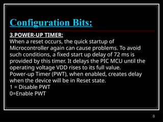
3.POWER-UP TIMER:
Whena reset occurs, the quick startup of
Microcontroller again can cause problems. To avoid
such conditions, a fixed start up delay of 72 ms is
provided by this timer. It delays the PIC MCU until the
operating voltage VDD rises to its full value.
Power-up Timer (PWT), when enabled, creates delay
when the device will be in Reset state.
1 = Disable PWT
0=Enable PWT
9.
9
Configuration Bits:
4. BROWN-OUTRESET (BOR):
Brown-out Reset (BOR), when enabled, resets the device
if the supply voltage VDD drops below VBOR for time
longer than TBOR. Once this situation occurs, the device
will remain in Brown-out reset until VDD rises above
VBOR.
VBOR about 4V
TBOR about 100 µS
1=Enable BOR
0=Disable BOR
10.
10
Configuration Bits:
5. LOW-VOLTAGE(SINGLE-SUPPLY):
The LVP (low voltage programming) bit of the
configuration enables low voltage ICSP programming. It
will allow microcontroller to program though ICSP by
using VDD source within the operation voltage range.
So in short we can say that VDD does not have to bring
to high voltage.
Operation:
In this mode, the RB3/PGM pin is dedicated to the
programming function.During programming, VDD is
applied to the MCLR pin. To enter Programming mode,
VDD must be applied to the RB3/PGM provided the LVP
bit is set. By default from the factory the LVP bit is set to
1. If Low-Voltage Programming mode is not used, the
11.
11
Configuration Bits:
6. DATAEEPROM MEMORY CODE PROTECTION BIT
(CPD):
PIC 16F877A has an internal EEPROM data. Two bits,
CPD and WRTD, protect the entire data EEPROM.
External reads and writes of data EEPROM is controlled
by CPD. CPD Configuration Bit protect this region of
memory against reading and external recordings (i.eIn-
circuit Serial Programming)
Operation:
1 = Data EEPROM code protection off (Disable)
0 = Data EEPROM code-protected (Enable)
12.
12
Configuration Bits:
7. FLASHPROGRAM MEMORY WRITE:
These bits enable writing in the flash memory by the
use of EECON. We can write data directly into the Flash
memory by the device firmware. Simply, we can say that
the sectors of our choice can be selected for the
recording of data or for the In-circuit Serial
Programming.
13.
13
Configuration Bits:
8. IN-CIRCUITDEBUGGER MODE:
Debugging process allows the execution and tracking
the code. This process read variables and execution
step-by-step. Pins RB6 and RB7 can be used as in-circuit
debugger pins.
Operation:
1=In-Circuit Debugger Disabled
0=In-Circuit Debugger Enabled (RB6 and RB7 are
dedicated to the Debugger)
When enabled>>debug process
When disabled>>allows use as digital inputs and
outputs
14.
14
Configuration Bits:
9. FLASHMEMORY CODE PROTECTION:
If the program is stored in the flash memory then this
bit is responsible for enabling the code protection.
Operation:
Once enabled, the Flash memory (program memory)
will be copy and protected. It cannot be read then.
1=Protection Code off (CP
Disabled)
0=All Program memory code Protected (CP
Enable)
16
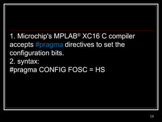
1. Microchip's MPLAB®
XC16C compiler
accepts #pragma directives to set the
configuration bits.
2. syntax:
#pragma CONFIG FOSC = HS
17.
17
Setting the ConfigurationBits in MPLAB-X:
Step 1: Click on Window -> PIC Memory
View -> Configuration Bits. As shown below.
18.
18
Step 2: Thisshould open the Configuration Bits window in the bottom of our
IDE as shown below. This is the place where we can set each of the
configuration bits according to our needs. I will explain each of the bits and its
purpose as we progress through the steps.
19.
19
Step 3: Thefirst Bit is the oscillator selection bit.
The PIC16F87XA can be operated in four different oscillator modes.
These four modes can be selected by programming two configuration
bits (FOSC1 and FOSC0):
LP Low-Power Crystal
XT Crystal/Resonator
HS High-Speed Crystal/Resonator
RC Resistor/Capacitor
For our projects we are using a 20Mhz Osc hence we have to select
the HS from the dropdown box.
20.
20
Once the settingsare done as instructed the Dialog box should look
something like this.
22
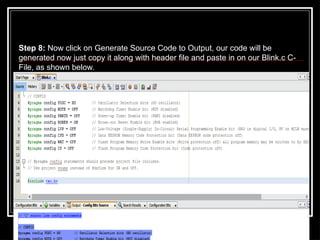
Step 8: Nowclick on Generate Source Code to Output, our code will be
generated now just copy it along with header file and paste in on our Blink.c C-
File, as shown below.