SlideShare a Scribd company logo
1 of 47
1
Performance boosting of Li-S batteries using ZIF-67 derived CoOx
as a polysulfide suppressing catalyst
Abstract
Lithium sulfide (Li2S)-based lithium-sulfur batteries (LSBs) are considered a promising
candidate for next-generation energy storage batteries due to their high energy density. Controlling
the dissolution of polysulfides (PS) and improving the electronic conductivity of Li2S cathode are
the two main problems for the practical application of Li-S batteries. To tackle those problems by
designing porous nanocages of three-dimensional (3D) cobalt oxide (N-Co3O4), prepared from
ZIF-67 by simple pyrolysis method. Subsequently, embedded with two-dimensional (2D)
graphene oxide nanoribbons (rGONR) and one-dimensional (1D) carbon nanotubes (CNTs) to
form N-Co3O4/rGONR/CNT metal-carbon composite. Here, Li2S has infiltrated into the double-
shelled N-Co3O4 and rGONR/CNT (N-Co3O4/C) porous nanocage structure as sulfur host
materials through the infiltration-evaporation method. The deliberately designed 2D/1D carbon
matrix offers a fast electron and ion transfer route, suitable surface area, and pore size for redox
reactions and polysulfide confinement. Furthermore, porous N-Co3O4 filler could synergistically
immobilize polysulfides inside the cathode through chemisorption to impede the shuttle effect in
LSBs. The deliberately designed N-Co3O4/C with a spinel-based structure could serve as a
transition metal catalyst to facilitate Li2S oxidation with minimized polarization in the first cycle.
Benefited from the advantages, the as-fabricated Li2S-N-Co3O4/rGONR/CNT composite cathode,
which is coupled with lithium metal as the anode, delivers initially a high specific capacity of 1004
mA h g-1
at 0.1C and good retention capability of 413 mA h g-1
after 1000 cycles at 3C. Therefore,
2
the excellent electrochemical performance of the N-Co3O4/C modified composite cathode suggests
its promising prospects for the commercial application of LSBs in high-energy storage devices.
Keywords: Porous cobalt oxide nanocages, Carbon nanotube; Li2S based cathode, Polysulfide
confinement, Low activation potential; Li-S battery.
1. Introduction
Lithium-sulfur (Li-S) batteries are regarded as promising candidates for next-generation
rechargeable batteries due to their high theoretical capacity and energy density1-3
. For a
conventional Li-S battery system, employing sulfur as the cathode, and lithium as the anode faces
a few problems. For example, the large volume expansion (∼80 vol %) during initial discharge
could result in structural damage to the electrodes. The dissolution of polysulfide intermediates in
organic electrolyte deposits on the Li anode side forms an irreversible product which leads to low
coulombic efficiency and dendrite formation3-5
. Lithium is incorporated into the lithium sulfide
(Li2S) and is used as the cathode material owing to its high theoretical specific capacity (1166
mAh g-1
) and the lithium-metal-free anode. In addition, electrode compression occurs in
delithiation and provides enough space to accommodate the volume expansion of sulfur during
lithiation, thereby ensuring cyclic stability for Li-S batteries3, 6-9
. However, the potential barrier in
the first cycle, low sulfur utilization, low electronic conductivity (e∼10-13
S cm-1
) of the Li2S
active material, and the polysulfide shuttle effect are the primary tasks for the practical application
of Li-S batteries10-12
.
Various methods have been employed to address these issues. The in situ Li2S synthesis is
often carried out using toxic or unstable reactants and is not cost-effective12-14
. For instance, the
3
infiltration evaporation method is utilized to reduce the particle size of Li2S, thereby overcoming
the insulating barrier through shortened diffusion length and enlarged contact surfaces12, 15
.
Moreover, Li2S is infiltrated into the carbonaceous material such as graphene, reduced graphene
oxide, porous carbon, and carbon nanotube structure. Those carbon materials act as a host material
to ensure high electronic conductivity and the utilization of sulfur during discharge. Among these,
porous carbon does not offer sufficient loading and internal resistance compared to other carbon
materials. Meanwhile, the combined 2D reduced graphene oxide (rGO) and 1D carbon nanotube
(CNT) offer sufficient pore size and surface area for Li2S. This three-dimensional (2D/1D)
architecture is helpful to decrease the internal resistance and increase the loading of Li2S9, 12
.
However, the three-dimensional carbon matrix is not enough to immobilize dissolved polysulfides
due to weak intermolecular interaction between non-polar carbon material and polar LiPS
species12, 16
.
Development of metal compounds with abundant polar active sites has been proven to
strongly bind with LiPSs by polar-polar interactions, and Lewis’s acid-base interactions thus
effectively entrapping them within the surface of the cathode16
. Recent studies found that
electrocatalysts such as metal oxides17, 18
, metal sulfides19, 20
, and metal-organic frameworks
(MOFs)16, 21
can assist the catalytic conversion of soluble polysulfide in a chemical way, which
improves the utilization of active sulfur and suppresses the ‘shuttle effect’. Compared with other
materials, metal oxides derived from the metal-organic framework (MOF) have attracted much
attention because of their higher adsorption of LiPSs and simple preparation process21
. In addition,
the heteroatom dopant sites (N, P, O, and S) derived from MOFs can also provide additional
affinity for soluble polysulfides, which could assist the strong chemical interactions between Li2S
and LiPSs. Meanwhile, nitrogen-doped carbon materials improve the active sites on the surface
4
and promote electrochemical reactions as well as electronic conductivity16
. However, many polar
metallic compounds are insufficient to provide the electronic conductivity required for Li2S.
Therefore, the favourable design of 3D N-Co3O4 combined with a mixed 2D/1D carbon matrix
containing polar polysulfide-anchoring materials synergistically enhances polysulfide
confinement and facilitates rapid electron transfer, thus contributing to the better electrochemical
performance of Li-S batteries18, 21
.
In this study, we synthesized 3D porous N-doped cobalt oxide nanocages embedded with
an rGONR/CNT carbon matrix to provide abundant active sites and open channels for Li2S
nanoparticles to construct the cathode material. Moreover, the Li2S successfully inserts into highly
porous interconnected structures as a 3D carbon host by the infiltration method3, 12
. This could
offer strong adsorption of soluble polysulfides and enhance the performance of Li-S batteries. The
synergistic effect of double-shelled N-Co3O4/C structures is responsible for the various merits of
Li2S cathodes. First, the outer 2D rGONR/1D CNT carbon matrix has a high surface area and
abundant uniform micropores is beneficial for confining Li2S active material inside the cathode.
This provides highly efficient channels for ionic diffusion and electron transfer and prevents fast
dissolution of polysulfides through physical adsorption. In addition, the inner porous polar N-
Co3O4 composite with rGONR/CNT significantly confines polysulfide migration out of the
framework through strong chemical interactions. It facilitates the catalytic effect in the initial Li2S
oxidation activation cycle. Thus, the high activation barrier of Li2S oxidation for the Li2S/N-
Co3O4/rGONR/CNT composite is alleviated and the long-term cycling performance could be
significantly improved. Therefore, it could be introduction of the porous N-Co3O4 metal oxide
with the two carbon matrices enhances the electronic conductivity and high ability to accommodate
sulfur during cycling. As expected, our Li2S/N-Co3O4/rGONR/CNT cathode delivers high specific
5
capacity, with remarkable high-rate performance, and ensures outstanding high C-rate
performance, demonstrating the superiority of N-Co3O4/carbon hierarchical structures.
2. Experimental
2.1Synthesis of rGONR Materials
MWCNTs were used as received from CNT Co., Ltd. (product name, CTube-120; diameter
= 10–40 nm; length = 1–25 μm). H2SO4, H3PO4, and KMnO4 were purchased from J.T. Baker. The
ink was prepared using Nafion solution (Du Pont, USA, 5 wt.%).
Oil-Bath Assisted Synthesis of rGONR
GONR was synthesized through a modified oil-bath method like that of previous studies22,
23
. MWCNTs (0.05 g) were suspended in H2SO4/H3PO4 (=9:1, v/v) and stirred for 24 h. KMnO4
(0.25 g) was added to the solution before placing it in an oil bath (66–68 ℃) for 8 h. The solution
was filtered using a Millipore membrane (0.1 μm pore size) to isolate the product as the residue.
The product (GONR) was washed several times with distilled water and freeze-dried for 12 h. The
as-prepared GONR powder was reduced at 600 °C for 2 h in a 5% H2/95% Ar atmosphere to form
a reduced graphene oxide nanoribbon (rGONR).
2.2Synthesis of ZIF-67 Powders
Firstly, 4.5 g of 2-methylimidazole (Sigma-Aldrich, 99%) was dissolved in 140 mL of
deionized water followed by stirring for 20 min, denoted as solution A. Then 0.58 g of Co
(NO3)2⋅6H2O (ACS, 98%) was added into 50 mL deionized water under stirring and ultrasonic
treatment for 10 min, denoted as solution B. In addition, solution A was poured into solution B
6
slowly and the mixture was magnetically stirred for 24 h. After centrifuge, the purple precipitate
was washed by ethanol for three times and dried in a vacuum chamber at 80°C for 24 h to obtain
ZIF-67 powder. The SEM image of ZIF-67 particles is illustrated in Figure S1. It shows a well-
uniform rhombic dodecahedral shape with a smooth surface and the particle is distributed in the
range of average size around ~1 µm.
2.3Synthesis of N-Co3O4 Nanocages
The as-prepared ZIF-67 powders were annealed at 550 °C in an N2 atmosphere with a
heating rate of 5°C min-1
for 3 h, resulting in the porous N-Co3O4 nanocages. The schematic
illustration of the preparation of N-Co3O4 nanocages is shown in Scheme 1.
Scheme 1. (a) Schematic for preparing an N-Co3O4 nanocage powder.
2.4Synthesis of N-Co3O4/rGONR/CNT Composite Active Materials
7
Take 4 mg of synthesized N-Co3O4 dispersed in ethanol solution and stirred for 1 h. Then,
add an ultrasonically dispersed solution containing 4 mg of as-prepared reduced graphene oxide
nanoribbon (rGONR) and 12 mg of CNT for 12 h to get an N-Co3O4/rGONR/CNT composite.
2.5Synthesis of Li2S-N-Co3O4/rGONR/CNT Composite
The Li2S-N-Co3O4/rGONR/CNT composite was prepared by using the infiltration-
evaporation method. Specifically, 80 mg of Li2S powder (Alfa Aesar, 99.9% MW = 45.95) was
dissolved in absolute ethanol (≥99.8%, GC, Aladdin) to form a solution of 0.1 M primarily. Then,
it was infiltrated into the 20 mg of prepared N-Co3O4/rGONR/CNT composite solution and stirred
for 12 h. The resulting suspension was dried by evaporating the ethanol solvent to obtain the Li2S-
N-Co3O4/rGONR/CNT composite. This process assisted in the encapsulation of Li2S within the
N-Co3O4/C matrix to enhance the electronic conductivity of the active material. All the processes
were conducted under an Ar atmosphere. The Li2S-rGONR/CNT composite preparation follows
all the Li2S-N-Co3O4/rGONR/CNT composite preparation steps.
8
Scheme 2. (a) represents the Li2S-N-Co3O4/rGONR/CNT composite preparation method.
2.6Electrode Preparation
The cathode slurry was prepared by mixing the Li2S-N-Co3O4/rGONR/CNT composite
material with a Super P and PVDF binder at a weight ratio of 80:10:10 in an N-methyl pyrrolidone
(NMP) solvent using a Thinky mixer (Japan). The as-obtained slurry was then cast onto a carbon-
coated Al foil and vacuum-dried at 70 ℃ for 24 h. After that, the cathode was punched into discs
(Ø = 13 mm) and used for a 2032-type coin cell assembly. The calculated mass loading of the Li2S
active material was 1.5 mg cm-2
. This procedure was performed in an Ar glove box. elemental
analysis (EA) showed that the Li2S content in the cathode material was ca. 61 wt.%.
2.7Electrochemical Performance Measurements
9
All electrochemical measurements were conducted on 2032-type coin cells containing
Celgard 2500 PP separator. The electrolyte consisted of a 1 M lithium bis (trifluoromethyl sulfonyl)
imide (LiTFSI) in 1, 2-dimethoxyethane (DME) and 1, 3-dioxolane (DOL) (1:1 v/v) with 2 wt.%
of LiNO3; Li foil (200 μm, Sigma) was used as the anode. The prepared coin cell was initially
activated at 3.6 V, followed by cycles of charging/discharging in the voltage range of 1.8 to 2.7 V.
Cyclic voltammetry tests were conducted at a scan rate of 0.05 mV s-1
between 1.8 and 3.6 V (vs.
Li/Li+
) during the initial cycle using an electrochemical workstation. For the following cycles, the
scan rate and operation voltage were adjusted to 0.1 mV s-1
and 1.8 to 2.8 V, respectively. Cyclic
voltammetry (CV) and Electrochemical impedance spectroscopy (EIS) were performed using a
Metrohm Autolab PGSTAT32N (The Netherlands) electrochemical workstation; EIS
measurements were conducted within a frequency range of 1 MHz–100 mHz at an amplitude of 5
mV.
2.8 Material Characterization
X-ray diffraction (XRD; Bruker D2 PHASER, Germany; Cu Kα; λ = 0.15406 nm; 30 kV,
10 mA) was used to study the crystalline and amorphous nature of the materials within the range
of 10−80°. Morphological microanalysis of the separator, Li anode, and their elemental
distributions was performed using scanning electron microscopy (SEM; Hitachi S-2600H, Japan)
with energy dispersive X-ray spectrometry (EDS). N adsorption/desorption isotherms were
measured at 77 K by using a BJ builder Kubo X1000 apparatus, the Brunauer–Emmett–Teller
(BET) method, and the Barrett–Joyner–Hallender (BJH) approach. The Li2S content in the
composite sample was examined using an elemental analyzer (Thermal Flash 2000). The
absorbability of the LiPSs on the samples was assessed via UV−vis absorption using a Cary 60
UV−vis spectrophotometer (Jasco V-670). XPS (Thermo Fisher/K-Alpha) was used to examine
10
the oxidation states and elemental compositions at the sub-surfaces of the materials; the peaks were
fitted using XPSPEAK41 software.
2.9 Preparation of Li2S6 Solution for Adsorption Test
S and Li2S were magnetically mixed at a 5:1 molar ratio in DOL/DME (1:1, v/v%) solvents
under an Ar-blanket to prepare a 0.1 M Li2S6 solution. As-prepared Li2S-rGONR/CNT and Li2S-
N-Co3O4/rGONR/CNT P (0.1 g) were then added to 4 mL of the Li2S6 PS solution for the LiPSs
adsorption experiment.
3. Results and Discussion
3.1Structural and Morphological Studies
Figure 1(a-c) shows the SEM image of one-dimensional (1D) CNT containing numerous
nanowires observed. Additionally, numerous 2D mesoporous sheets were observed on the two-
dimensional (2D) sheet structure of reduced graphene oxide nanoribbon (rGONR), and porous
nanocages present in the (3D) structure N-Co3O4. Furthermore, the elemental mapping of the N-
Co3O4 composite showed that N, Co, and O were uniformly distributed in Figure S2. Many
nanowires are present on the surface of Li2S-N-Co3O4/rGONR/CNT composite materials. Further,
a cross-sectional SEM image of the cathode as mentioned above showed many pores, volume, and
nanoribbons that assisted with S storage and utilization due to the mixed carbon matrix in Figure
S3. Through the transmission electron microscopy (TEM) image, Figure 1(d) displays the well-
defined porous structure that assists in inserting Li2S particles. Li2S particles are decorated and
covered by the nanoribbons and nanotubes (Figure 1(e-f)).
11
Figure 1. The top-view SEM images of (a) CNT, (b) rGONR carbon material, (c) N-Co3O4
nanocages, TEM images of (d) N-Co3O4 nanocage, (e-f) Li2S-N-Co3O4/rGONR/CNT
composite material.
In the Li2S-N-Co3O4/rGONR/CNT composite, Li2S is uniformly distributed through the
composite which is confirmed in EDX mapping in Figure S4. The favorable strategies to create
voids in porous N-Co3O4/C nanocage structure for Li2S penetration through an infiltration method.
In addition, this N-Co3O4/C structure behaved as physical confinement as well as chemical
interaction with long-chain Li-polysulfides (LiPSs), as shown in Scheme 2. Based on XPS results,
the presence of nitrogen and cobalt sites immobilizes the LiPSs and suppresses the PS shuttle
effect; therefore, they can significantly enhance conversion reaction kinetics. The uniform and
porous carbonaceous coating ensured the facile penetration of the electrolyte through the cathode
material to facilitate Li+
-ion conductivity. This also suppresses the internal resistance and delivers
high discharge capacity.
12
Scheme 3. Schematic illustration of the full-cell configuration based on the Li2S-N-
Co3O4/rGONR/CNT composite cathode with a PP separator.
The XRD peak of the Li2S-rGONR/CNT composite was observed at 27, 31.2, 44.8, 53.1,
55.6, 65.2, 71.9, and 74°, which corresponded to the standard Li2S phase. Compared with uncoated
Li2S, the Li2S-rGONR/CNT and Li2S-N-Co3O4/rGONR/CNT composite electrodes exhibited
weaker and broader XRD peaks, which may be attributed to the decreased particle size of the
composites Figure 2(a). The characteristic peaks of rGONR and CNT were not observed in the
composite electrodes because of their low crystallinity and content. Li2S-N-Co3O4/rGONR/CNT
composite can be indexed to the Fd-3m symmetry Co3O4 peaks. The sharp peaks of XRD patterns
indicate the well-defined crystalline of the materials. Figure 2(b) shows the electrical
conductivities of the Li2S-rGONR/CNT (ca. 3.37 × 10⁻³
S cm−1
) and Li2S-N-Co3O4/rGONR/CNT
(ca. 3.75 × 10⁻³
S cm−1
) electrodes. The electrical conductivity of Li2S-N-Co3O4/rGONR/CNT
slightly increased due to suitable amounts of N-Co3O4 fillers in cathode composite. This indicates
13
that the N-Co3O4/C-based electrode with a dual-carbon matrix performed better than the Li2S-
based electrode with a rGONR/CNT carbon matrix.
Figure 2(c) shows Brunauer–Emmett–Teller (BET) surface area of Li2S-N-
Co3O4/rGONR/CNT composites was higher. However, the surface area of rGONR/CNT was
increased when combined with N-Co3O4/C from 54.6 to 60.1 m2
g-1
upon composite synthesis.
The presence of a type IV isotherm with a hysteresis loop indicates uniform and well-tuned pore
size in the matrix of the Li2S-N-Co3O4/rGONR/CNT composite during mixing, which is consistent
with the narrow pore size distribution around 2 to 14 nm in Figure 2(d). In contrast, we found that
the pore size distribution of the Li2S-rGONR/CNT composite possesses broad pores from 0 to 18
nm. Additionally, the N-Co3O4/C modified composite demonstrates higher pore volume, surface
area, and well-tuned pore size distribution, which could offer sufficient free volume or space and
active sites for electrolyte infiltration as well as strengthened Li-polysulfides entrapment
capability12
.
14
Figure 2. (a) XRD results of bare Li2S, rGONR, CNT, N-Co3O4, Li2S-rGONR/CNT, and Li2S-N-
Co3O4/rGONR/CNT composites, (b) the electronic conductivity measurements, and (c)
the nitrogen adsorption-desorption BET isotherm curves, (d) The pore size distribution
of Li2S-rGONR/CNT and Li2S-N-Co3O4/rGONR/CNT composite fillers.
Figure 3(a-c) illustrates the chemical states of these functional groups in the N-Co3O4/C
composite materials that were analyzed using XPS. The deconvoluted C1s spectrum exhibited C-
C, C=C, and C–N/C=N peaks at 284.8, 285.9, and 288.9 eV, respectively16
. In addition, the N 1s
spectrum reveals the presence of N moieties was confirmed in the porous N-Co3O4 nanocages; in
particular, 398.8 eV, 400.1 eV, and 404.5 eV correspond to the pyridinic, pyrrolic, and quaternary
15
N groups, respectively24, 25
. The pyridinic N has strong binding energy with PS by polar-polar
interaction. Furthermore, the Co 2p spectrum shows two main peaks corresponding to Co 2p3/2 and
Co 2p1/2, respectively. Further, the two main peaks are divided into a total of four peaks, and the
two peaks appear at 780.2 and 796.2 eV is attributed to the presence of Co3+
, while the two peaks
appearing at 781.9 and 803.3eV represents Co2+
peak26, 27
. In addition, cobalt can accelerate the
conversion of soluble long-chain Li-polysulfides to Li2S, thereby promoting the conversion
reaction kinetics and yielding a high specific capacity. Furthermore, the peak at 786.2eV assigned
to Co-N improves the chemisorption of soluble polysulfides16
, thus the sulfur utilization and
cycling stability. The synergistic effects of Co-N and C-N bonding have a significant impact in
enhancing the electrochemical performance of Li-S batteries.
To validate and demonstrate the LiPS adsorption properties of the rGONR/CNT and N-
Co3O4/ rGONR/CNT composites, a classic LiPSs adsorption test was performed using 0.1 M Li2S6
in DOL/DME (1:1, v/v). Post-adsorbed supernatants of both samples were then subjected to UV-
vis absorption; the results are shown in Figure 3(d). The dominant absorption peaks corresponded
to the S6
2–
species of Li2S6, which were observed at 265 and 279 nm28, 29
. These peaks were
significantly suppressed by the addition of N-Co3O4 materials, thereby supporting its excellent
adsorption capacity for LiPSs. Our as-prepared composite cathode material may hinder the
shuttling of LiPSs, thus prolonging the cell's lifespan and improving the practicality application
for the Li2S cathode. Images of the composite material during the adsorption test at different time
intervals are shown in Figure 3(e). The color changes indicate the effective absorption of LiPSs
over the N-Co3O4/C composite materials after 12 h. In contrast, the brown supernatant in the Li2S6
solution after adsorption suggests that the absorption ability of rGONR/CNT powders were
inferior.
16
Figure 3. (a) XPS spectra for N-Co3O4/C composite, (a) C 1s, (b) N 1s, and (d) Co 2p, (e) UV–Vis
spectra of the lithium polysulfide were taken after being a stand for 12 h. (f) Digital
photographs of Li-polysulfide adsorption tests of (i) Li2S6 solution; (ii) rGONR/CNT
composite with Li2S6; (iii) N-Co3O4/rGONR/CNT composite materials with Li2S6 at
different period times of 0, 3, 6 and 12 h.
17
3.2Electrochemical Performance Studies
Figure 4(a) shows the charge transfer resistance of the fresh cell with the Li2S-N-
Co3O4/rGONR/CNT composite (ca. 19.6 Ω) was marginally lower than that of the cell with the
Li2S-rGONR/CNT (ca. 30.5 Ω). Herein, the N-Co3O4/C porous structure composite filler can
reduce Rct value, enabling faster Li+
ion diffusivity through charge-discharge. After 5 cycles, the
Rt total resistance becomes less than fresh cells with a stable solid electrolyte interface (SEI)
formation in Figure 4(b). The obtained values of Rct of the N-Co3O4 modified sample were lower
than those of the unmodified sample, indicating enhanced initial discharge capacity and lower
electrochemical polarization. The AC equivalent circuit model is demonstrated in the inset of
Figures 4(a) and (b) as well, where the Rb, Rct, Wo, and SEI are named as bulk resistance, the
charge-transfer resistance, the solid electrolyte interface, and Warburg diffusion impedance,
respectively30, 31
.
𝐷𝐿𝑖+ =
𝑅2𝑇2
2𝐴2𝑛4𝐹4𝑐2𝜎2
(1)
Where DLi+, R, T, A, n, F, c, and σ refer to the diffusion coefficient of Li+
, the gas constant,
the absolute temperature, the area of the electrode, the number of transfer electrons, the Faraday
constant, the concentration of Li+
, and the fitting slope respectively. The slope (σ) is obtained from
the fitting results, as shown in Figures 4 (c) and (d), the Li2S-N-Co3O4/rGONR/CNT electrode
has a smaller slope, indicating fast ion transport.
18
Figure 4. (a) Nyquist plots of the fresh cell (The inset: Equivalent circuit model), and (b) After 5
cycles with Li2S-rGONR/CNT and Li2S-N-Co3O4/rGONR/CNT composites, (c) Tafel
plot of Li2S-rGONR/CNT and Li2S-N-Co3O4/rGONR/CNT composites for fresh and
after 5 cycles.
In general, Li2S electrodes must overcome a large potential barrier at their first charging
cycle at 0.05C in the voltage range of 1.8-3.6 V (vs. Li/Li+
). The activation barrier was attributed
to the high charge-transfer resistance in the delithiating Li2S, which was due to its poor electronic
conductivity and low Li+
-ion diffusivity. Figure 5 shows that the barrier occurs in the Li2S-
rGONR/CNT cathode, due to Li-polysulfide nucleation around the Li2S particles during charging.
19
Therefore, the initial charge transfer between the active material, electrolyte, and the conductive
material was sluggish due to the insulating nature of Li2S. In Li/Li2S-N-Co3O4/rGONR/CNT
composite-based cells, lower activation potential (ca. 2.5 V) than that of the cell containing the
Li2S-rGONR/CNT composite (ca. 3.2 V). The uniform pore size distribution of the N-Co3O4/C-
modified composite, which assisted in the smooth Li+
ion diffusion from Li2S, resulted in a
significant decrease in polarization in the activation cycle. This occurred because it accelerated the
oxidation of Li2S during the first charging cycle.
Figure 5. First cycle charge voltage profiles of the cells based on Li2S-rGONR/CNT and Li2S-N-
Co3O4/rGONR/CNT composite cathodes.
The galvanostatic charge-discharge (GCD) profiles for the Li/Li2S-N-Co3O4/rGONR/CNT
and Li/Li2S-rGONR/CNT-based cells with the PP separator at 0.1C within the range of 1.82.7 V
(vs. Li/Li+
) are shown in Figures 6(a) and (b). The first charge-discharge curve exhibited two
plateaus during the charge and two plateaus during the discharge. This corresponded to the phase
20
transformations from solid to liquid and liquid to solid, which was consistent with the CV curve.
During the first charging cycle, the potential barrier completely disappears, and a single plateau
indicates the fast conversion kinetic behavior in the Li2S-N-Co3O4/rGONR/CNT composite
cathode. The initial discharge capacity of the Li/Li2S-N-Co3O4/rGONR/CNT-based cell was
approximately 1006 mAh g-1
, which is higher than that of the cells with Li2S-rGONR/CNT (941
mAh g-1
). The initial discharge capacity of the cell based on Li2S-N-Co3O4/rGONR/CNT increased
by 7% than that of the Li2S-rGONR/CNT composite. This is due to the high Li+
ion diffusion
coefficient, which permitted rapid reaction kinetics and smooth delithiating from the Li2S-N-
Co3O4/rGONR/CNT composite on the cathode, which may be responsible for the minimal
activation overpotential.
Cyclic voltammetric analyses were conducted at a scan rate of 0.1 mv s−1
in the range of
1.8-2.7 V (vs. Li/Li+
) (Figures 6(c) and (d)). The CV curves exhibited two reduction peaks; the
peak at approximately 2.3 V corresponded to the reduction of S8 to soluble Li2Sn (4 ≤ n ≤ 8),
whereas the peak at 2.0 V was associated with Li2Sn reduction (4 ≤ n ≤ 8) to insoluble Li2S2/Li2S.
Additionally, the oxidation peak at 2.4 V was mainly associated with the oxidation of Li2S2/Li2S
to Li2Sn (4 ≤ n ≤ 8). The polarization (E = 0.26 V) between the oxidation peak and the reduction
peak of the cell based on Li2S-N-Co3O4/rGONR/CNT cathode was lower than that of the cells
based on Li2S-rGONR/CNT cathode (E = 0.32 V). This showed that the cell based on the Li2S-
N-Co3O4/rGONR/CNT facilitated LiPSs conversion and enhanced the electrochemical properties.
Furthermore, the corresponding current intensity of the cell based on the Li2S-N-
Co3O4/rGONR/CNT cathode was the highest one during the redox reaction. The CV curves of the
first three cycles indicate that the N-Co3O4-modified cathode improved electronic conductivity
and provided excellent electrochemical performances.
21
Figure 6. (a-c) Galvanostatic charge-discharge profiles and overpotential measurements of the
Li2S-rGONR/CNT and Li2S-N-Co3O4/rGONR/CNT composites at 0.1C; (d-f) Cyclic
voltammetry profiles of the Li2S-rGONR/CNT and Li2S-N-Co3O4/rGONR/CNT
composites at a scan rate of 0.1 mV s-1
.
3.3Li+
Diffusion Coefficient by a CV Method
Cyclic voltammograms (CV) were performed at different Scan rates from 0.1 to 0.5 mV s-
1
. The lithium-ion transfer was analyzed by calculating the lithium-ion diffusion coefficient using
the Randles−Sevcik equation32, 33
,
22
𝑖𝑝 = 2.69 × 10⁵
𝑛1.5
𝐴 𝐷𝐿𝑖
0.5
𝐶𝐿𝑖 𝜈0.5
(2)
where ip represents the peak current (A), concentration (lithium ions) represents the
concentration of lithium ions in the electrolyte (mol cm-3
), DLi represents the lithium-ion diffusion
coefficient (cm2
s-1
), the area represents the area of the active electrode (cm2
), v represents the
scanning rate (V s-1
), and n represents the number of electrons transferred.
Using Eqn. (2) to calculate Li+
-ion diffusion coefficient values which are presented in
Table S2. The improved initial discharge capacity is interpreted by the Li2S-N-
Co3O4/rGONR/CNT electrode displays a much higher lithium-ion diffusion coefficient and peak
current than the Li2S-rGONR/CNT one in Figures 7(a-b). This indicates its faster ion transfer
takes place on the surface of the cathode. From Figures 7(c-d), it was obvious that the slope values
for both the cathodic and anodic peaks of Li2S-N-Co3O4/rGONR/CNT electrode were the largest,
which was mainly due to the synergistic effect of N-Co3O4 and rGONR/CNT, facilitating the
migration of Li+
ion. Even with a scan rate at 0.5 mV s-1
, the Li2S-N-Co3O4/rGONR/CNT electrode
maintains the reductive peak at 2.0 V, demonstrating fast reaction kinetics to overcome barriers.
Furthermore, the long cycling life of the N-Co3O4/C cathode is also a key factor in the battery’s
performance.
23
Figure 7. (a-b) Cyclic voltammograms at different scan rates, and (c-d) represents the plots of the
peak current versus the square root of the scan rates for Li2S-rGONR/CNT and Li2S-N-
Co3O4/rGONR/CNT electrodes.
3.5Rate Capability and Electrochemical Performance
The two composite cathodes at various current densities ranging from 0.2 to 5C were used
to examine the different C-rate profiles. Figure 8(a) shows that cells based on Li2S-N-
Co3O4/rGONR/CNT cathode were delivered with average discharge capacities of 927, 853, 793,
690, and 624 mAh g-1
at current rates from 0.2 0.5, 1, 3, and 5C stepwise, and come back to 0.2C,
24
respectively, assigning to a 92% capacity retention. Concurrently, the cell based on Li2S-
rGONR/CNT cathode rapidly declined from 853, 772, 701, 588, and 517 mAh g-1
at current rates
of 0.2, 0.5, 1, 3, and 5C, respectively, and gives 88% capacity retention when returning to 0.2C.
The specific discharge capacity for the cells based on Li2S-N-Co3O4/rGONR/CNT at a low to high
current rate (0.2~5C) was increased by 8%, 10%,13%,17%, and 21%, as compared to that of the
cell based on Li2S-rGONR/CNT. Overall, the higher capacity retention of Li2S-N-
Co3O4/rGONR/CNT, it is due to 3D porous N-Co3O4 nanocage fillers. They can assist the rapid
conversion reaction rate, maintaining the structural stability of the cathode at high C-rates.
Consequently, the cell based on N-Co3O4/C-modified composite has a high Li+
diffusion
coefficient and is primarily responsible for the increased discharge capacity and greater kinetic
reversibility after a high current rate. The respective charge/discharge curve is attached in Figure
S5.
To further investigate the long-term cycling performance of the two cells was evaluated at
1C/1C at room temperature. The initial coulombic efficiency of the cell based on Li2S-N-
Co3O4/rGONR/CNT is approximately 93%, which is higher than that of the cell based on Li2S-
rGONR/CNT composite (86%), as shown in Figure S6. This implies that the high utilization of
sulfur occurs in the first cycle. Figure 8(b) illustrates the cell based on Li2S-N-
Co3O4/rGONR/CNT provided the highest initial specific capacity of 786 mAh g−1
at 1C (1C =
1166 mA g−1
in our Li-S battery). The specific discharge capacity was maintained at 500 mAh g−1
with stabilized coulombic efficiency of 99% and slow capacity decay of 0.045% per cycle after
800 cycles. In contrast, the cells based on Li2S-rGONR/CNT exhibited initial specific capacities
of 703 mAh g-1
at 1C, respectively; however, these were reduced to approximately 313 mAh g-1
after 800 cycles. Moreover, rapid fading was observed during the long-term cycling of the cells
25
based on Li2S-rGONR/CNT composite. This was possibly due to the migration of LiPSs through
the separator and reduced as irreversible loss of Li2S, which may result in a more severe LiPSs
shuttling effect. The cell based on Li2S-N-Co3O4/rGONR/CNT at 1C/1C exhibited a higher
specific capacity with gradual fading during charge/discharge. The doubled-shell N-Co3O4/C
design assisted in suppressing the polysulfide migration during cycling. This may be attributed to
the good surface area and active sites to store and reuse the dissolved LiPSs, which extends cycling
life.
The Nyquist plots of the aged cells based on Li2S-N-Co3O4/rGONR/CNT and Li2S-
rGONR/CNT cathodes after cycling at 1C/1C for 800 cycles. Two semicircles (RSEI and Rct) and
Warburg diffusion impedances (W0) were observed in Figure S7. The values are listed in Table
S1. The SEI layer of the cells based on Li2S-N-Co3O4/rGONR/CNT was compact and stable (it
showed lower RSEI value of 1.5–3 ; see Table S1), which can maintain stable Li+
ion transport.
However, the difference between the respective resistances of the cells based on Li2S-N-
Co3O4/rGONR/CNT was limited, indicating that the conducting outer layer containing
rGONR/CNT particles did not increase the internal resistance at the interface. Comparatively, the
increase in resistance of the cells based on Li2S-rGONR/CNT may be due to unstable SEI
characteristics after prolonged cycling.
3.5.1 Higher Current Rates and Long-Term Cycling Investigation
The remarkable performance of Li2S-N-Co3O4/rGONR/CNT cathodes was evaluated
under various conditions to establish their viability for the practical application of Li-S batteries.
In half-cell, Li2S-N-Co3O4/rGONR/CNT cathode paired with Li foil shows an extremely stable
cycling behaviour at a 3C rate (1C = 1166 mA g-1
) with an impressive lifespan of over 1000 cycles
in Figure 8(c). The mass loading of Li2 S is ca. 1.5 mg cm-2
assembled with an electrolyte/Li2S
26
ratio of 37 μL mg-1
. It should be noted that the cell based on Li2S-rGONR/CNT cathode can only
deliver 413 mA h g-1
after 1000 cycles. This difference in the cycling performance between Li2S-
N-Co3O4/rGONR/CNT and Li2S-rGONR/CNT cathodes reaffirm the supremacy of N-Co3O4/C
fillers in Li-S cells. Also, the average coulombic efficiency of the cell based on Li2S-N-
Co3O4/rGONR/CNT is much higher than that of the cell based on Li2S-rGONR/CNT. This reveals
that polysulfide shuttling is suppressed via the N-Co3O4/C porous structure fillers in a cathode.
After 500 cycles, lower coulombic efficiency and fast capacity fading were observed during the
long-term cycling of the cells based on Li2S-rGONR/CNT. This was possibly due to the electrolyte
used in LSBs that may decompose during cycling. This results in the formation of passivation
layers on the electrode surface or the generation of insoluble reaction side products, both of which
can adversely affect the high-rate electrochemical performance.
27
Figure 8. (a) The rate capabilities for the cells based on Li2S-rGONR/CNT and Li2S-N-
Co3O4/rGONR/CNT composites from 0.2 to 5C rates, Long-term cycling performances
of the cells based on Li2S-rGONR/CNT and Li2S-N-Co3O4/rGONR/CNT composites at
(b) 1C/1C for 800 cycles at RT, (c) 3C/3C for 1000 cycles at RT.
3.5.2 Structural Evolution of Cycled Electrodes and Separators
28
After long cycling (at 1C/1C for 800cycles), inspect the electrode stability of bare and
cycled electrodes by using an SEM image. Figures S8(a) and (d) show the untreated Li2S-N-
Co3O4/rGONR/CNT and Li2S-rGONR/CNT composite cathodes show smooth surfaces and are
well coated on Al foil. During cycling, porous interconnected structures facilitate the fast insertion
and de-insertion of Li+
ion. After 800 cycles, cracking and agglomeration observed in the aged
Li2S composite electrode were observed, indicated by the red circle in Figure S8(b-c) and S8(e-
f), possibly owing to the impact of the severe LiPSs shuttering reactions. In Li2S-N-
Co3O4/rGONR/CNT electrode shows a smooth surface with no agglomeration. This demonstrates
that the N-Co3O4/C modified composite cathode exhibited excellent structural stability during the
charge-discharge process, with no evident cracks found even after 800 cycles at a high current
density of 1C, as compared to the 2D rGONR/1D CNT modified composite cathode.
Figure S9(a-d) shows the SEM surface morphologies of the aged PP separators for Li2S-
N-Co3O4/rGONR/CNT and Li2S-rGONR/CNT electrodes (after 800 cycles) at different
magnifications. In Li2S-rGONR/CNT electrode, observe LiPS residues deposited on the surface
of the aged PP separator, indicated yellow layer on a digital photo of the PP separator, shown in
Figure S9(a-b). This blocked the pores of the PP separator, which affects the Li+
ion transport.
This explained the capacity fading of the cycling cell and the active material loss after 800 cycles.
In contrast, the morphologies of the Li2S-N-Co3O4/rGONR/CNT cathode with the cycled PP
separator are shown in Figure S9(c-d), respectively. The aged PP separator exhibited a clean and
uniform surface. No yellow layer on the separator surface was observed. This was attributed to the
good catalytic property of the 3D porous N-Co3O4 fillers, which fasted up the LiPS conversion
reaction and a better suppression of the shuttle effect during long-term cycling.
3.6Postmortem Analysis of Li Anode
29
The two cells containing Li foils were disassembled after 800 cycles and the surface
morphology of the cycled Li anodes was examined using SEM. Figure 9(a-b) shows the SEM
images of the cycled Li metal. The surface of the Li2S-rGONR/CNT-based cell with aged Li metal
was rough and noticeable mossy Li dendrites in Figure 9(a). The rough surface exhibited a
substantial surface area because of electrolyte decomposition and severe side reactions on the Li
anode. These unfavorable side reactions resulted in an increase in the formation of dead Li, which
caused an increase in overpotential; the thick aged Li anode was obtained. Conversely, the aged Li
anode taken from the Li2S-N-Co3O4/rGONR/CNT-based cell maintained a smooth Li anode
surface. The well interconnected structure of the N-Co3O4/C composite traps dissolved
polysulfides to suppress Li dendrite growth on the anode side, as shown in Figure 9(b).
Figure 9(c-d) displays a cross-sectional SEM image of the aged Li anode after 800 cycles.
This was determined based on the increase in total Li anode thickness to ca. 459.6 μm, indicating
the accumulation of many dead Li during charge/discharge as shown in Figure 9(c). In contrast,
the aged Li anode from the Li2S-N-Co3O4/rGONR/CNT-based cell exhibited a smooth
morphology devoid of mossy Li dendrite growth. The total thickness of the cycled Li anode was
ca. 362.3 μm, as displayed in Figure 9(d). Compared to the Li2S-rGONR/CNT, the volume
expansion of the aged Li anode from the Li2S-N-Co3O4/rGONR/CNT-based cell was suppressed.
This may be due to the highly catalytic activity of the N-Co3O4 fillers, which can also prevent the
migration of polysulfides.
30
Figure 9. (a-b) The top-view SEM images of the cycled Li metal anode, (c-d) The cross-sectional
view SEM images of the cycled Li anode taken from Li2S-rGONR/CNT-based and Li2S-
N-Co3O4/rGONR/CNT-based cells after 800 cycles, respectively.
Table 1 lists the results from previous studies on Li2S-based S batteries and this study. The
increase in specific discharge capacity of the Li2S-N-Co3O4/rGONR/CNT-based cell with PP
separators was higher than that of the other studies. The reasons were due to the following: (1) the
multiple interactions with LiPSs induced by N-Co3O4 fillers and nitrogen dopant allow highly
active sites available to trap LiPSs. The high electronic conductivity generated by both 2D rGONR
and 1D CNT carbon framework facilitates the transport of electrons during the conversion reaction.
These two factors synergistic together result in excellent interfacial electrochemical kinetics; (2)
31
the presence of highly active sites in the MOF-derived (ZIF67) polar hosts are beneficial to
accommodate sulfur and LiPSs. This can significantly improve electrochemical performances and
assist in the long-term cycling stability of the cells; (3) rGONR/CNT acts as a physical sulfur
reservoir or matrix, reducing the LiPSs dissolution into the electrolyte and maximizing the
utilization of sulfur. As a result, the initial voltage barrier of the Li2S-N-Co3O4/rGONR/CNT
composite is greatly alleviated, and the long cycling performance is distinctly enhanced.
Table 1. Comparison studies of Li2S-based battery performance with literature data.
Data
Cathodes
Separato
r
Li2S
content
(wt.%)
Potential
Barrier
(V)
High-rate capability
(mAh g-1
)
Long-term cycling
performance
Capaci
ty
retenti
on
Refere
nce
Li2S/Ti3C2 PP 56 2.85 750@0.1C–360@2C 100 cycles@0.2C 60% 28
Li2S/p-C3N4/CNT PP 48 2.4 892@0.1C–501@2C
200 cycles@0.5C
600 cycles@2C
69%
56%
34
Li2S/Co@C PP 67.7 3.12 886@0.05C–148@3C 500 cycles@0.1C 33% 35
Li2S-Mo@C PP 47.7 2.51 821@0.2C–314@5C
70 cycles@0.1C
500 cycles@1C
68%
47%
36
Li2S/CNT/GO/PPy PP 64.7 2.52 857@0.2C–524@2C 400 cycles@2C 74% 37
32
Li2S-N-
Co3O4/rGONR/CNT
PP 61 2.39 927@0.2C–624@5C
800 cycles@1C
1000 cycles@3C
64%
65%
Curre
nt
study
4. Conclusions
In summary, we synthesized double-shelled N-Co3O4/C porous nanocage as Li2S host for
Li-S battery. The Li2S-N-Co3O4/rGONR/CNT composite was successfully prepared and used as
an electrode in Li2S-based batteries. Additionally, the N-Co3O4/C-based electrode significantly
reduced the internal resistance due to the three-dimensional pathway provided by the double-
shelled structure. Thus, the well interconnected micro/mesoporous structure of the Li2S-N-
Co3O4/rGONR/CNT composites improved the Li+
ion diffusion coefficient and electron transport.
The synergistic effect of the deliberately designed N-Co3O4/C porous structure was further tuned
for Li-polysulfide immobilization. Along with this physical confinement, N-cobalt oxide
nanocages exhibited both physical/chemical sequestration of polysulfides and acted as
electrocatalysts to promote the conversion reaction kinetics. Moreover, our mixed hierarchical
electrode design markedly enhanced Li2S active material utilization; however, it also immobilized
LiPS migration to suppress dendrite formation.
Consequently, the Li2S-based cell based on Li2S-N-Co3O4/rGONR/CNT exhibited a long
lifespan of 800 cycles with a high reversible capacity of 500 mAh g-1
at 1C/1C.Acapacity retention
of 64% and a capacity attenuation per cycle of only 0.045% were achieved. According to the high
C-rate results, the combination of 3D N-doped cobalt oxide with 2D/1D carbon matrix can
33
synergistically improve the polysulfide confinement and electrochemical performance of Li-S
batteries. It was found that the incorporation of the rGONR/CNT dual-carbon with 3D porous
cobalt oxide fillers is a promising way for Li-S battery practical applications.
34
5. Reference
(1) Manthiram, A.; Fu, Y.; Chung, S. H.; Zu, C.; Su, Y. S. Rechargeable lithium-sulfur batteries.
Chem Rev 2014, 114 (23), 11751-11787.
(2) He, J.; Chen, Y.; Li, P.; Fu, F.; Wang, Z.; Zhang, W. Three-dimensional CNT/graphene–sulfur
hybrid sponges with high sulfur loading as superior-capacity cathodes for lithium-sulfur batteries.
Journal of Materials Chemistry A 2015, 3 (36), 18605-18610.
(3) He, J.; Chen, Y.; Lv, W.; Wen, K.; Xu, C.; Zhang, W.; Li, Y.; Qin, W.; He, W. From Metal-
Organic Framework to Li2S@C-Co-N Nanoporous Architecture: A High-Capacity Cathode for
Lithium-Sulfur Batteries. ACS Nano 2016, 10 (12), 10981-10987.
(4) Li, Z.; Li, C.; Ge, X.; Ma, J.; Zhang, Z.; Li, Q.; Wang, C.; Yin, L. Reduced graphene oxide
wrapped MOFs-derived cobalt-doped porous carbon polyhedrons as sulfur immobilizers as
cathodes for high performance lithium sulfur batteries. Nano Energy 2016, 23, 15-26.
(5) Zhang, K.; Xu, Y.; Lu, Y.; Zhu, Y.; Qian, Y.; Wang, D.; Zhou, J.; Lin, N.; Qian, Y. A graphene
oxide-wrapped bipyramidal sulfur@polyaniline core-shell structure as a cathode for Li-S batteries
with enhanced electrochemical performance. Journal of Materials Chemistry A 2016, 4 (17), 6404-
6410.
(6) Fan, F. Y.; Carter, W. C.; Chiang, Y. M. Mechanism and Kinetics of Li2S Precipitation in
Lithium-Sulfur Batteries. Adv Mater 2015, 27 (35), 5203-5209.
(7) Seh, Z. W.; Wang, H.; Liu, N.; Zheng, G.; Li, W.; Yao, H.; Cui, Y. High-capacity Li2S–graphene
oxide composite cathodes with stable cycling performance. Chemical Science 2014, 5 (4).
(8) Sun, D.; Hwa, Y.; Shen, Y.; Huang, Y.; Cairns, E. J. Li2S nano spheres anchored to single-
layered graphene as a high-performance cathode material for lithium/sulfur cells. Nano Energy
2016, 26, 524-532.
35
(9) He, J.; Chen, Y.; Lv, W.; Wen, K.; Xu, C.; Zhang, W.; Qin, W.; He, W. Three-Dimensional
CNT/Graphene–Li2S Aerogel as Freestanding Cathode for High-Performance Li–S Batteries. ACS
Energy Letters 2016, 1 (4), 820-826.
(10) Yang, Y.; Zheng, G.; Misra, S.; Nelson, J.; Toney, M. F.; Cui, Y. High-Capacity Micrometer-
Sized Li2S Particles as Cathode Materials for Advanced Rechargeable Lithium-Ion Batteries.
Journal of the American Chemical Society 2012, 134 (37), 15387-15394.
(11) Wu, F.; Lee, J. T.; Fan, F.; Nitta, N.; Kim, H.; Zhu, T.; Yushin, G. A Hierarchical Particle-Shell
Architecture for Long-Term Cycle Stability of Li2S Cathodes. Adv Mater 2015, 27 (37), 5579-
5586.
(12) Liu, H.; Zeng, P.; Li, Y.; Yu, H.; Chen, M.; Jamil, S.; Miao, C.; Chen, G.; Liu, Q.-C.; Luo, Z.;
Wang, X. Polyaniline-Derived Carbon Heterostructure as Redox Mediator of Li2S Oxidation and
Polysulfide Immobilizer for High-Performance Lithium–Sulfur Cathode. ACS Sustainable
Chemistry & Engineering 2020, 8 (44), 16659-16670.
(13) Li, X.; Gao, M.; Du, W.; Ni, B.; Wu, Y.; Liu, Y.; Shang, C.; Guo, Z.; Pan, H. A
mechanochemical synthesis of submicron-sized Li2S and a mesoporous Li2S/C hybrid for high
performance lithium/sulfur battery cathodes. Journal of Materials Chemistry A 2017, 5 (14), 6471-
6482.
(14) Ye, H.; Li, M.; Liu, T.; Li, Y.; Lu, J. Activating Li2S as the Lithium-Containing Cathode in
Lithium–Sulfur Batteries. ACS Energy Letters 2020, 5 (7), 2234-2245.
(15) Ting, L. K. J.; Gao, Y.; Wang, H.; Wang, T.; Sun, J.; Wang, J. Lithium Sulfide Batteries:
Addressing the Kinetic Barriers and High First Charge Overpotential. ACS Omega 2022, 7 (45),
40682-40700.
36
(16) Xu, J.; Zhang, W.; Chen, Y.; Fan, H.; Su, D.; Wang, G. MOF-derived porous N–Co3O4@N-C
nanododecahedral wrapped with reduced graphene oxide as a high capacity cathode for lithium-
sulfur batteries. Journal of Materials Chemistry A 2018, 6 (6), 2797-2807.
(17) Li, Z.; Zhang, J.; Guan, B.; Wang, D.; Liu, L. M.; Lou, X. W. A sulfur host based on titanium
monoxide@carbon hollow spheres for advanced lithium-sulfur batteries. Nat Commun 2016, 7,
13065.
(18) Xia, S.; Zhou, Q.; Peng, B.; Zhang, X.; Liu, L.; Guo, F.; Fu, L.; Wang, T.; Liu, Y.; Wu, Y.
Co3O4@MWCNT modified separators for Li-S batteries with improved cycling performance.
Materials Today Energy 2022, 30.
(19) Chen, T.; Ma, L.; Cheng, B.; Chen, R.; Hu, Y.; Zhu, G.; Wang, Y.; Liang, J.; Tie, Z.; Liu, J.;
Jin, Z. Metallic and polar Co9S8 inlaid carbon hollow nanopolyhedra as efficient polysulfide
mediator for lithium−sulfur batteries. Nano Energy 2017, 38, 239-248.
(20) He, J.; Chen, Y.; Manthiram, A. Metal Sulfide‐Decorated Carbon Sponge as a Highly Efficient
Electrocatalyst and Absorbant for Polysulfide in High‐Loading Li2S Batteries. Advanced Energy
Materials 2019, 9 (20).
(21) Zhou, L.; Li, H.; Wu, X.; Zhang, Y.; Danilov, D. L.; Eichel, R.-A.; Notten, P. H. L. Double-
Shelled Co3O4/C Nanocages Enabling Polysulfides Adsorption for High-Performance Lithium–
Sulfur Batteries. ACS Applied Energy Materials 2019, 2 (11), 8153-8162.
(22) Sun, C.-L.; Chang, C.-T.; Lee, H.-H.; Zhou, J.; Wang, J.; Sham, T.-K.; Pong, W.-F.
Microwave-Assisted Synthesis of a Core-Shell MWCNT/GONR Heterostructure for the
Electrochemical Detection of Ascorbic Acid, Dopamine, and Uric Acid. ACS Nano 2011, 5 (10),
7788-7795.
37
(23) Kosynkin, D. V.; Higginbotham, A. L.; Sinitskii, A.; Lomeda, J. R.; Dimiev, A.; Price, B. K.;
Tour, J. M. Longitudinal unzipping of carbon nanotubes to form graphene nanoribbons. Nature
2009, 458 (7240), 872-876.
(24) Sun, F.; Wang, J.; Chen, H.; Li, W.; Qiao, W.; Long, D.; Ling, L. High efficiency
immobilization of sulfur on nitrogen-enriched mesoporous carbons for Li-S batteries. ACS Appl
Mater Interfaces 2013, 5 (12), 5630-5638.
(25) Gu, M.; Wang, J.; Song, Z.; Li, C.; Wang, W.; Wang, A.; Huang, Y. Multifunctional
Asymmetric Separator Constructed by Polyacrylonitrile-Derived Nanofibers for Lithium-Sulfur
Batteries. ACS Appl Mater Interfaces 2023.
(26) Wang, Y.; Li, X.; Wu, L.; Tan, J.; Liu, G.; Ye, C.; Ma, L.; Liu, Z.; Ye, M.; Shen, J. Highly
lithiophilic and uniform Co-MOF-derived ultrathin Co3O4 nanoarrays enable dendrite-free lithium
metal anode. Energy Storage Materials 2024, 66.
(27) Wang, Q.; Ma, Y.; Wang, Z.; Liu, Z.; Xu, X.; Ma, Z.; Wang, Y.; Du, Y.; Lei, W. Blanket biochar
loaded with nano-Co3O4/graphite heterostructure assisted polysulfide trapping for high-stability
lithium sulfur batteries. Journal of Physics and Chemistry of Solids 2024, 188.
(28) Liang, X.; Yun, J.; Xu, K.; Xiang, H.; Wang, Y.; Sun, Y.; Yu, Y. A multi-layered Ti3C2/Li2S
composite as cathode material for advanced lithium-sulfur batteries. Journal of Energy Chemistry
2019, 39, 176-181.
(29) Raj Deivendran, G.; Wu, S.-H.; Wu, Y.-S.; Chang, J.-K.; Jose, R.; Ng, K. H.; Poddar, M.; Sun,
C.-L.; Yang, C.-C. Suppression of Polysulfides by Carbonized Polyacrylonitrile Modified
Polypropylene Janus Separator for Li2S/r-GONR/CNT-Based Li–S Batteries. ACS Applied Energy
Materials 2024.
38
(30) Wang, J.; Jia, L.; Duan, S.; Liu, H.; Xiao, Q.; Li, T.; Fan, H.; Feng, K.; Yang, J.; Wang, Q.;
Liu, M.; Zhong, J.; Duan, W.; Lin, H.; Zhang, Y. Single atomic cobalt catalyst significantly
accelerates lithium ion diffusion in high mass loading Li2S cathode. Energy Storage Materials
2020, 28, 375-382.
(31) Jeyakumar, J.; Wu, Y.-S.; Wu, S.-H.; Jose, R.; Yang, C.-C. Surface-Modified Quaternary
Layered Ni-Rich Cathode Materials by Li2ZrO3 for Improved Electrochemical Performance for
High-Power Li-Ion Batteries. ACS Applied Energy Materials 2022, 5 (4), 4796-4807.
(32) Tao, X.; Wang, J.; Liu, C.; Wang, H.; Yao, H.; Zheng, G.; Seh, Z. W.; Cai, Q.; Li, W.; Zhou,
G.; Zu, C.; Cui, Y. Balancing surface adsorption and diffusion of lithium-polysulfides on
nonconductive oxides for lithium-sulfur battery design. Nat Commun 2016, 7, 11203.
(33) Chen, M.; Zhao, S.; Jiang, S.; Huang, C.; Wang, X.; Yang, Z.; Xiang, K.; Zhang, Y.
Suppressing the Polysulfide Shuttle Effect by Heteroatom-Doping for High-Performance Lithium–
Sulfur Batteries. ACS Sustainable Chemistry & Engineering 2018, 6 (6), 7545-7557.
(34) Liang, S.; Chen, J.; Zhou, N.; Hu, L.; Liu, L.; Wang, L.; Liang, D.; Yu, T.; Tian, C.; Liang, C.
CNT threaded porous carbon nitride nanoflakes as bifunctional hosts for lithium sulfide cathode.
Journal of Alloys and Compounds 2021, 887, 161356.
(35) Yang, H.; Lei, Y.; Yang, Q.; Zhang, B.-W.; Gu, Q.; Wang, Y.-X.; Chou, S.; Liu, H.-K.; Dou,
S.-X. Cobalt-induced highly-electroactive Li2S heterostructured cathode for Li-S batteries.
Electrochimica Acta 2023, 439, 141652.
(36) Liang, S.; Dong, R.; Lu, S.; Hu, L.; Liu, L.; Dong, Q.; Deng, C.; Qin, G.; Xu, M.; Liang, C.
Green synthesis of fig–like Li2S–Mo@C nanocomposites for advanced lithium–sulfur batteries.
Electrochimica Acta 2022, 426.
39
(37) Liu, H.; Zeng, P.; Yu, H.; Zhou, X.; Li, Z.; Chen, M.; Miao, C.; Chen, G.; Wu, T.; Wang, X.
Enhancing the electrochemical performances of Li2S-based cathode through conductive interface
design and addition of mixed conductive materials. Electrochimica Acta 2021, 396, 139238.
40
Supporting Information
Performance boosting of Li-S batteries using ZIF-67 derived CoOx as a
polysulfide suppressing catalyst
The total number of pages: 8 (S1-S8)
The total number of Figures: 10 (Figure S1-Figure S10)
The total number of Tables: 1 (Table S1)
Figure S1. SEM images of ZIF-67 particles.
41
Figure S2. EDX mapping results of N-Co3O4 with the presence of elements N, Co, and O.
42
Figure S3. (a-b) display SEM images of Li2S-N-Co3O4/rGO/CNT composite material and (c)
shows the cross-sectional images of Li2S-N-Co3O4/rGO/CNT cathodes.
43
Figure S4. EDX mapping results of Li2S-N-Co3O4/rGO/CNT composite with the presence of
elements S, Co, C, and N.
Figure S5. GCD voltage profiles of rate capability for (a) Li2S-N-Co3O4/rGO/CNT and Li2S-
/rGO/CNT cathodes at various current densities from 0.2 to 2 C.
Figure S6. GCD voltage profiles of long-term cycling performance for (a) Li2S-N-
Co3O4/rGO/CNT and Li2S-/rGO/CNT cathodes at 1C rate for 800 cycles.
44
Figure S7. The EIS spectra of cells containing (a) Li2S-r-GO/CNT, (b) Li2S-N-Co3O4/r-
GONR/CNT at 1C/1C after 800 cycles.
45
Figure S8. (a-c) The SEM images of fresh and cycled composite cathodes were taken from the
cells containing (a-c) Li2S-r-GO/CNT after 800 cycles and (d-f) the cells containing
Li2S-N-Co3O4/r-GO/CNT cathode.
46
Figure S9. The SEM images (a-b) separators taken from the cycled cell containing (a-b) Li2S-r-
GO/CNT (c-d) Li2S-N-Co3O4/r-GO/CNT after 800 cycles at different magnifications
of 5k and 10k; the inset: cycled OM images for both cathodes.
Table S1. Rb, RSEI, Rct, Rt values of the Li2S-N-Co3O4/rGO/CNT|PP|Li and Li2S-rGO/CNT| PP|Li
cells before and after 800 cycles.
Battery system
Before cycling
Rb () RSEI () Rct () Rt ()
Li2S-rGO/CNT|PP|Li 2.1 - 30.5 32.6
Li2S-N-Co3O4/rGO/CNT|PP| Li 1.4 - 19.6 21.0
47
Battery system
After 5 cycles
Rb () RSEI () Rct () Rt ()
Li2S-rGO/CNT|PP|Li 2.8 8.0 12.0 22.8
Li2S-N-Co3O4/rGO/CNT|PP| Li 1.5 7.3 6.7 15.5
Battery system
After 800 cycles
Rb () RSEI () Rct () Rt ()
Li2S-rGO/CNT|PP|Li 7.5 3.2 9.3 20
Li2S-N-Co3O4/rGO/CNT|PP| Li 2.3 1.6 4.5 8.4
Note: Rt = Rb + RSEI + Rt.
Table S2. Lithium-ion diffusion coefficient analysis of Li2S-rGO/CNT and Li2S-N-
Co3O4/rGO/CNT composite, using the Randles-Sevcik equation: ipeak = 268,600 × e1.5
× area × coefficientLi-ion
0.5
× concentrationLi-ion × rate0.5
, where ipeak is the peak current,
e is the number of electrons, area is the electrode area, concentrationLi-ion is the
lithium-ion diffusion concentration in the electrolyte, and the rate is the scanning rate.
concentrationLi-ion (cm2 S-1) a1 c1 c2
Li2S-rGO/CNT 5.34 × 10⁻⁶
1.39 × 10⁻⁶
1.05 × 10⁻⁶
Li2S-N-Co3O4/rGO/CNT 4.7 × 10⁻⁶
8.33 × 10⁻⁷
7.82 × 10⁻⁷

More Related Content

Similar to Performance boosting of Li-S batteries using ZIF-67 derived CoOx as polysulfide catalyst.docx

Electrochemical Investigation of Electrolyte & Anodic Materials for Sodium Io...
Electrochemical Investigation of Electrolyte & Anodic Materials for Sodium Io...Electrochemical Investigation of Electrolyte & Anodic Materials for Sodium Io...
Electrochemical Investigation of Electrolyte & Anodic Materials for Sodium Io...CrimsonPublishersRDMS
 
Nitrogen-Enriched Carbon Nanobubbles and Nanospheres for Applications in Ener...
Nitrogen-Enriched Carbon Nanobubbles and Nanospheres for Applications in Ener...Nitrogen-Enriched Carbon Nanobubbles and Nanospheres for Applications in Ener...
Nitrogen-Enriched Carbon Nanobubbles and Nanospheres for Applications in Ener...Devika Laishram
 
Water-splitting photoelectrodes consisting of heterojunctions of carbon nitri...
Water-splitting photoelectrodes consisting of heterojunctions of carbon nitri...Water-splitting photoelectrodes consisting of heterojunctions of carbon nitri...
Water-splitting photoelectrodes consisting of heterojunctions of carbon nitri...Devika Laishram
 
Vapor growth of binary and ternary phosphorusbased semiconductors into TiO2 n...
Vapor growth of binary and ternary phosphorusbased semiconductors into TiO2 n...Vapor growth of binary and ternary phosphorusbased semiconductors into TiO2 n...
Vapor growth of binary and ternary phosphorusbased semiconductors into TiO2 n...Pawan Kumar
 
Water-splitting photoelectrodes consisting of heterojunctions of carbon nitri...
Water-splitting photoelectrodes consisting of heterojunctions of carbon nitri...Water-splitting photoelectrodes consisting of heterojunctions of carbon nitri...
Water-splitting photoelectrodes consisting of heterojunctions of carbon nitri...Pawan Kumar
 
Graphene oxide immobilized copper phthalocyanine tetrasulphonamide: the first...
Graphene oxide immobilized copper phthalocyanine tetrasulphonamide: the first...Graphene oxide immobilized copper phthalocyanine tetrasulphonamide: the first...
Graphene oxide immobilized copper phthalocyanine tetrasulphonamide: the first...Pawan Kumar
 
Carbon based catalysts for oxygen reduction reaction (ORR)
Carbon based catalysts for oxygen reduction reaction (ORR) Carbon based catalysts for oxygen reduction reaction (ORR)
Carbon based catalysts for oxygen reduction reaction (ORR) Lav Kumar Kasaudhan
 
Vapor Deposition of Semiconducting Phosphorus Allotropes into TiO2 Nanotube A...
Vapor Deposition of Semiconducting Phosphorus Allotropes into TiO2 Nanotube A...Vapor Deposition of Semiconducting Phosphorus Allotropes into TiO2 Nanotube A...
Vapor Deposition of Semiconducting Phosphorus Allotropes into TiO2 Nanotube A...Pawan Kumar
 
C-C Cross Coupling Reactions in Organic chemistry by Anthony crasto
C-C Cross Coupling Reactions in Organic chemistry by Anthony crastoC-C Cross Coupling Reactions in Organic chemistry by Anthony crasto
C-C Cross Coupling Reactions in Organic chemistry by Anthony crastoAnthony Melvin Crasto Ph.D
 
Vapor growth of binary and ternary phosphorus-based semiconductors into TiO 2...
Vapor growth of binary and ternary phosphorus-based semiconductors into TiO 2...Vapor growth of binary and ternary phosphorus-based semiconductors into TiO 2...
Vapor growth of binary and ternary phosphorus-based semiconductors into TiO 2...Pawan Kumar
 
Hexamolybdenum clusters supported on graphene oxide: Visible-light induced ph...
Hexamolybdenum clusters supported on graphene oxide: Visible-light induced ph...Hexamolybdenum clusters supported on graphene oxide: Visible-light induced ph...
Hexamolybdenum clusters supported on graphene oxide: Visible-light induced ph...Pawan Kumar
 
Vapor Deposition of Semiconducting Phosphorus Allotropes into TiO2 Nanotube A...
Vapor Deposition of Semiconducting Phosphorus Allotropes into TiO2 Nanotube A...Vapor Deposition of Semiconducting Phosphorus Allotropes into TiO2 Nanotube A...
Vapor Deposition of Semiconducting Phosphorus Allotropes into TiO2 Nanotube A...Pawan Kumar
 
High rate CO2 photoreduction using flame annealed TiO2 nanotubes
High rate CO2 photoreduction using flame annealed TiO2 nanotubesHigh rate CO2 photoreduction using flame annealed TiO2 nanotubes
High rate CO2 photoreduction using flame annealed TiO2 nanotubesPawan Kumar
 
High rate CO2 photoreduction using flame annealed TiO2 nanotubes
High rate CO2 photoreduction using flame annealed TiO2 nanotubesHigh rate CO2 photoreduction using flame annealed TiO2 nanotubes
High rate CO2 photoreduction using flame annealed TiO2 nanotubesPawan Kumar
 

Similar to Performance boosting of Li-S batteries using ZIF-67 derived CoOx as polysulfide catalyst.docx (20)

Electrochemical Investigation of Electrolyte & Anodic Materials for Sodium Io...
Electrochemical Investigation of Electrolyte & Anodic Materials for Sodium Io...Electrochemical Investigation of Electrolyte & Anodic Materials for Sodium Io...
Electrochemical Investigation of Electrolyte & Anodic Materials for Sodium Io...
 
Nitrogen-Enriched Carbon Nanobubbles and Nanospheres for Applications in Ener...
Nitrogen-Enriched Carbon Nanobubbles and Nanospheres for Applications in Ener...Nitrogen-Enriched Carbon Nanobubbles and Nanospheres for Applications in Ener...
Nitrogen-Enriched Carbon Nanobubbles and Nanospheres for Applications in Ener...
 
Water-splitting photoelectrodes consisting of heterojunctions of carbon nitri...
Water-splitting photoelectrodes consisting of heterojunctions of carbon nitri...Water-splitting photoelectrodes consisting of heterojunctions of carbon nitri...
Water-splitting photoelectrodes consisting of heterojunctions of carbon nitri...
 
Vapor growth of binary and ternary phosphorusbased semiconductors into TiO2 n...
Vapor growth of binary and ternary phosphorusbased semiconductors into TiO2 n...Vapor growth of binary and ternary phosphorusbased semiconductors into TiO2 n...
Vapor growth of binary and ternary phosphorusbased semiconductors into TiO2 n...
 
Water-splitting photoelectrodes consisting of heterojunctions of carbon nitri...
Water-splitting photoelectrodes consisting of heterojunctions of carbon nitri...Water-splitting photoelectrodes consisting of heterojunctions of carbon nitri...
Water-splitting photoelectrodes consisting of heterojunctions of carbon nitri...
 
Graphene oxide immobilized copper phthalocyanine tetrasulphonamide: the first...
Graphene oxide immobilized copper phthalocyanine tetrasulphonamide: the first...Graphene oxide immobilized copper phthalocyanine tetrasulphonamide: the first...
Graphene oxide immobilized copper phthalocyanine tetrasulphonamide: the first...
 
Carbon based catalysts for oxygen reduction reaction (ORR)
Carbon based catalysts for oxygen reduction reaction (ORR) Carbon based catalysts for oxygen reduction reaction (ORR)
Carbon based catalysts for oxygen reduction reaction (ORR)
 
Vapor Deposition of Semiconducting Phosphorus Allotropes into TiO2 Nanotube A...
Vapor Deposition of Semiconducting Phosphorus Allotropes into TiO2 Nanotube A...Vapor Deposition of Semiconducting Phosphorus Allotropes into TiO2 Nanotube A...
Vapor Deposition of Semiconducting Phosphorus Allotropes into TiO2 Nanotube A...
 
C-C Cross Coupling Reactions in Organic chemistry by Anthony crasto
C-C Cross Coupling Reactions in Organic chemistry by Anthony crastoC-C Cross Coupling Reactions in Organic chemistry by Anthony crasto
C-C Cross Coupling Reactions in Organic chemistry by Anthony crasto
 
Vapor growth of binary and ternary phosphorus-based semiconductors into TiO 2...
Vapor growth of binary and ternary phosphorus-based semiconductors into TiO 2...Vapor growth of binary and ternary phosphorus-based semiconductors into TiO 2...
Vapor growth of binary and ternary phosphorus-based semiconductors into TiO 2...
 
Science(52) articulo analitica
Science(52) articulo analiticaScience(52) articulo analitica
Science(52) articulo analitica
 
Science(52) articulo analitica
Science(52) articulo analiticaScience(52) articulo analitica
Science(52) articulo analitica
 
Science(52) articulo analitica
Science(52) articulo analiticaScience(52) articulo analitica
Science(52) articulo analitica
 
Hexamolybdenum clusters supported on graphene oxide: Visible-light induced ph...
Hexamolybdenum clusters supported on graphene oxide: Visible-light induced ph...Hexamolybdenum clusters supported on graphene oxide: Visible-light induced ph...
Hexamolybdenum clusters supported on graphene oxide: Visible-light induced ph...
 
Hexamolybdenum clusters supported on graphene oxide: Visible-light induced ph...
Hexamolybdenum clusters supported on graphene oxide: Visible-light induced ph...Hexamolybdenum clusters supported on graphene oxide: Visible-light induced ph...
Hexamolybdenum clusters supported on graphene oxide: Visible-light induced ph...
 
CARBON-CUPROUS OXIDE COMPOSITE NANOPARTICLES ON GLASS TUBES FOR SOLAR HEAT CO...
CARBON-CUPROUS OXIDE COMPOSITE NANOPARTICLES ON GLASS TUBES FOR SOLAR HEAT CO...CARBON-CUPROUS OXIDE COMPOSITE NANOPARTICLES ON GLASS TUBES FOR SOLAR HEAT CO...
CARBON-CUPROUS OXIDE COMPOSITE NANOPARTICLES ON GLASS TUBES FOR SOLAR HEAT CO...
 
Vapor Deposition of Semiconducting Phosphorus Allotropes into TiO2 Nanotube A...
Vapor Deposition of Semiconducting Phosphorus Allotropes into TiO2 Nanotube A...Vapor Deposition of Semiconducting Phosphorus Allotropes into TiO2 Nanotube A...
Vapor Deposition of Semiconducting Phosphorus Allotropes into TiO2 Nanotube A...
 
Studying the Effect of Counter Ions on the Gas Selectivity and Volatile Organ...
Studying the Effect of Counter Ions on the Gas Selectivity and Volatile Organ...Studying the Effect of Counter Ions on the Gas Selectivity and Volatile Organ...
Studying the Effect of Counter Ions on the Gas Selectivity and Volatile Organ...
 
High rate CO2 photoreduction using flame annealed TiO2 nanotubes
High rate CO2 photoreduction using flame annealed TiO2 nanotubesHigh rate CO2 photoreduction using flame annealed TiO2 nanotubes
High rate CO2 photoreduction using flame annealed TiO2 nanotubes
 
High rate CO2 photoreduction using flame annealed TiO2 nanotubes
High rate CO2 photoreduction using flame annealed TiO2 nanotubesHigh rate CO2 photoreduction using flame annealed TiO2 nanotubes
High rate CO2 photoreduction using flame annealed TiO2 nanotubes
 

Recently uploaded

Chemical Tests; flame test, positive and negative ions test Edexcel Internati...
Chemical Tests; flame test, positive and negative ions test Edexcel Internati...Chemical Tests; flame test, positive and negative ions test Edexcel Internati...
Chemical Tests; flame test, positive and negative ions test Edexcel Internati...ssuser79fe74
 
Forensic Biology & Its biological significance.pdf
Forensic Biology & Its biological significance.pdfForensic Biology & Its biological significance.pdf
Forensic Biology & Its biological significance.pdfrohankumarsinghrore1
 
Creating and Analyzing Definitive Screening Designs
Creating and Analyzing Definitive Screening DesignsCreating and Analyzing Definitive Screening Designs
Creating and Analyzing Definitive Screening DesignsNurulAfiqah307317
 
Pests of cotton_Borer_Pests_Binomics_Dr.UPR.pdf
Pests of cotton_Borer_Pests_Binomics_Dr.UPR.pdfPests of cotton_Borer_Pests_Binomics_Dr.UPR.pdf
Pests of cotton_Borer_Pests_Binomics_Dr.UPR.pdfPirithiRaju
 
PossibleEoarcheanRecordsoftheGeomagneticFieldPreservedintheIsuaSupracrustalBe...
PossibleEoarcheanRecordsoftheGeomagneticFieldPreservedintheIsuaSupracrustalBe...PossibleEoarcheanRecordsoftheGeomagneticFieldPreservedintheIsuaSupracrustalBe...
PossibleEoarcheanRecordsoftheGeomagneticFieldPreservedintheIsuaSupracrustalBe...Sérgio Sacani
 
❤Jammu Kashmir Call Girls 8617697112 Personal Whatsapp Number 💦✅.
❤Jammu Kashmir Call Girls 8617697112 Personal Whatsapp Number 💦✅.❤Jammu Kashmir Call Girls 8617697112 Personal Whatsapp Number 💦✅.
❤Jammu Kashmir Call Girls 8617697112 Personal Whatsapp Number 💦✅.Nitya salvi
 
Animal Communication- Auditory and Visual.pptx
Animal Communication- Auditory and Visual.pptxAnimal Communication- Auditory and Visual.pptx
Animal Communication- Auditory and Visual.pptxUmerFayaz5
 
Recombinant DNA technology (Immunological screening)
Recombinant DNA technology (Immunological screening)Recombinant DNA technology (Immunological screening)
Recombinant DNA technology (Immunological screening)PraveenaKalaiselvan1
 
Nanoparticles synthesis and characterization​ ​
Nanoparticles synthesis and characterization​  ​Nanoparticles synthesis and characterization​  ​
Nanoparticles synthesis and characterization​ ​kaibalyasahoo82800
 
All-domain Anomaly Resolution Office U.S. Department of Defense (U) Case: “Eg...
All-domain Anomaly Resolution Office U.S. Department of Defense (U) Case: “Eg...All-domain Anomaly Resolution Office U.S. Department of Defense (U) Case: “Eg...
All-domain Anomaly Resolution Office U.S. Department of Defense (U) Case: “Eg...Sérgio Sacani
 
Hire 💕 9907093804 Hooghly Call Girls Service Call Girls Agency
Hire 💕 9907093804 Hooghly Call Girls Service Call Girls AgencyHire 💕 9907093804 Hooghly Call Girls Service Call Girls Agency
Hire 💕 9907093804 Hooghly Call Girls Service Call Girls AgencySheetal Arora
 
Green chemistry and Sustainable development.pptx
Green chemistry  and Sustainable development.pptxGreen chemistry  and Sustainable development.pptx
Green chemistry and Sustainable development.pptxRajatChauhan518211
 
Biogenic Sulfur Gases as Biosignatures on Temperate Sub-Neptune Waterworlds
Biogenic Sulfur Gases as Biosignatures on Temperate Sub-Neptune WaterworldsBiogenic Sulfur Gases as Biosignatures on Temperate Sub-Neptune Waterworlds
Biogenic Sulfur Gases as Biosignatures on Temperate Sub-Neptune WaterworldsSérgio Sacani
 
Pests of mustard_Identification_Management_Dr.UPR.pdf
Pests of mustard_Identification_Management_Dr.UPR.pdfPests of mustard_Identification_Management_Dr.UPR.pdf
Pests of mustard_Identification_Management_Dr.UPR.pdfPirithiRaju
 
GBSN - Microbiology (Unit 1)
GBSN - Microbiology (Unit 1)GBSN - Microbiology (Unit 1)
GBSN - Microbiology (Unit 1)Areesha Ahmad
 
Biopesticide (2).pptx .This slides helps to know the different types of biop...
Biopesticide (2).pptx  .This slides helps to know the different types of biop...Biopesticide (2).pptx  .This slides helps to know the different types of biop...
Biopesticide (2).pptx .This slides helps to know the different types of biop...RohitNehra6
 
Asymmetry in the atmosphere of the ultra-hot Jupiter WASP-76 b
Asymmetry in the atmosphere of the ultra-hot Jupiter WASP-76 bAsymmetry in the atmosphere of the ultra-hot Jupiter WASP-76 b
Asymmetry in the atmosphere of the ultra-hot Jupiter WASP-76 bSérgio Sacani
 
SAMASTIPUR CALL GIRL 7857803690 LOW PRICE ESCORT SERVICE
SAMASTIPUR CALL GIRL 7857803690  LOW PRICE  ESCORT SERVICESAMASTIPUR CALL GIRL 7857803690  LOW PRICE  ESCORT SERVICE
SAMASTIPUR CALL GIRL 7857803690 LOW PRICE ESCORT SERVICEayushi9330
 
Disentangling the origin of chemical differences using GHOST
Disentangling the origin of chemical differences using GHOSTDisentangling the origin of chemical differences using GHOST
Disentangling the origin of chemical differences using GHOSTSérgio Sacani
 

Recently uploaded (20)

Chemical Tests; flame test, positive and negative ions test Edexcel Internati...
Chemical Tests; flame test, positive and negative ions test Edexcel Internati...Chemical Tests; flame test, positive and negative ions test Edexcel Internati...
Chemical Tests; flame test, positive and negative ions test Edexcel Internati...
 
Forensic Biology & Its biological significance.pdf
Forensic Biology & Its biological significance.pdfForensic Biology & Its biological significance.pdf
Forensic Biology & Its biological significance.pdf
 
Creating and Analyzing Definitive Screening Designs
Creating and Analyzing Definitive Screening DesignsCreating and Analyzing Definitive Screening Designs
Creating and Analyzing Definitive Screening Designs
 
Pests of cotton_Borer_Pests_Binomics_Dr.UPR.pdf
Pests of cotton_Borer_Pests_Binomics_Dr.UPR.pdfPests of cotton_Borer_Pests_Binomics_Dr.UPR.pdf
Pests of cotton_Borer_Pests_Binomics_Dr.UPR.pdf
 
PossibleEoarcheanRecordsoftheGeomagneticFieldPreservedintheIsuaSupracrustalBe...
PossibleEoarcheanRecordsoftheGeomagneticFieldPreservedintheIsuaSupracrustalBe...PossibleEoarcheanRecordsoftheGeomagneticFieldPreservedintheIsuaSupracrustalBe...
PossibleEoarcheanRecordsoftheGeomagneticFieldPreservedintheIsuaSupracrustalBe...
 
CELL -Structural and Functional unit of life.pdf
CELL -Structural and Functional unit of life.pdfCELL -Structural and Functional unit of life.pdf
CELL -Structural and Functional unit of life.pdf
 
❤Jammu Kashmir Call Girls 8617697112 Personal Whatsapp Number 💦✅.
❤Jammu Kashmir Call Girls 8617697112 Personal Whatsapp Number 💦✅.❤Jammu Kashmir Call Girls 8617697112 Personal Whatsapp Number 💦✅.
❤Jammu Kashmir Call Girls 8617697112 Personal Whatsapp Number 💦✅.
 
Animal Communication- Auditory and Visual.pptx
Animal Communication- Auditory and Visual.pptxAnimal Communication- Auditory and Visual.pptx
Animal Communication- Auditory and Visual.pptx
 
Recombinant DNA technology (Immunological screening)
Recombinant DNA technology (Immunological screening)Recombinant DNA technology (Immunological screening)
Recombinant DNA technology (Immunological screening)
 
Nanoparticles synthesis and characterization​ ​
Nanoparticles synthesis and characterization​  ​Nanoparticles synthesis and characterization​  ​
Nanoparticles synthesis and characterization​ ​
 
All-domain Anomaly Resolution Office U.S. Department of Defense (U) Case: “Eg...
All-domain Anomaly Resolution Office U.S. Department of Defense (U) Case: “Eg...All-domain Anomaly Resolution Office U.S. Department of Defense (U) Case: “Eg...
All-domain Anomaly Resolution Office U.S. Department of Defense (U) Case: “Eg...
 
Hire 💕 9907093804 Hooghly Call Girls Service Call Girls Agency
Hire 💕 9907093804 Hooghly Call Girls Service Call Girls AgencyHire 💕 9907093804 Hooghly Call Girls Service Call Girls Agency
Hire 💕 9907093804 Hooghly Call Girls Service Call Girls Agency
 
Green chemistry and Sustainable development.pptx
Green chemistry  and Sustainable development.pptxGreen chemistry  and Sustainable development.pptx
Green chemistry and Sustainable development.pptx
 
Biogenic Sulfur Gases as Biosignatures on Temperate Sub-Neptune Waterworlds
Biogenic Sulfur Gases as Biosignatures on Temperate Sub-Neptune WaterworldsBiogenic Sulfur Gases as Biosignatures on Temperate Sub-Neptune Waterworlds
Biogenic Sulfur Gases as Biosignatures on Temperate Sub-Neptune Waterworlds
 
Pests of mustard_Identification_Management_Dr.UPR.pdf
Pests of mustard_Identification_Management_Dr.UPR.pdfPests of mustard_Identification_Management_Dr.UPR.pdf
Pests of mustard_Identification_Management_Dr.UPR.pdf
 
GBSN - Microbiology (Unit 1)
GBSN - Microbiology (Unit 1)GBSN - Microbiology (Unit 1)
GBSN - Microbiology (Unit 1)
 
Biopesticide (2).pptx .This slides helps to know the different types of biop...
Biopesticide (2).pptx  .This slides helps to know the different types of biop...Biopesticide (2).pptx  .This slides helps to know the different types of biop...
Biopesticide (2).pptx .This slides helps to know the different types of biop...
 
Asymmetry in the atmosphere of the ultra-hot Jupiter WASP-76 b
Asymmetry in the atmosphere of the ultra-hot Jupiter WASP-76 bAsymmetry in the atmosphere of the ultra-hot Jupiter WASP-76 b
Asymmetry in the atmosphere of the ultra-hot Jupiter WASP-76 b
 
SAMASTIPUR CALL GIRL 7857803690 LOW PRICE ESCORT SERVICE
SAMASTIPUR CALL GIRL 7857803690  LOW PRICE  ESCORT SERVICESAMASTIPUR CALL GIRL 7857803690  LOW PRICE  ESCORT SERVICE
SAMASTIPUR CALL GIRL 7857803690 LOW PRICE ESCORT SERVICE
 
Disentangling the origin of chemical differences using GHOST
Disentangling the origin of chemical differences using GHOSTDisentangling the origin of chemical differences using GHOST
Disentangling the origin of chemical differences using GHOST
 

Performance boosting of Li-S batteries using ZIF-67 derived CoOx as polysulfide catalyst.docx

  • 1. 1 Performance boosting of Li-S batteries using ZIF-67 derived CoOx as a polysulfide suppressing catalyst Abstract Lithium sulfide (Li2S)-based lithium-sulfur batteries (LSBs) are considered a promising candidate for next-generation energy storage batteries due to their high energy density. Controlling the dissolution of polysulfides (PS) and improving the electronic conductivity of Li2S cathode are the two main problems for the practical application of Li-S batteries. To tackle those problems by designing porous nanocages of three-dimensional (3D) cobalt oxide (N-Co3O4), prepared from ZIF-67 by simple pyrolysis method. Subsequently, embedded with two-dimensional (2D) graphene oxide nanoribbons (rGONR) and one-dimensional (1D) carbon nanotubes (CNTs) to form N-Co3O4/rGONR/CNT metal-carbon composite. Here, Li2S has infiltrated into the double- shelled N-Co3O4 and rGONR/CNT (N-Co3O4/C) porous nanocage structure as sulfur host materials through the infiltration-evaporation method. The deliberately designed 2D/1D carbon matrix offers a fast electron and ion transfer route, suitable surface area, and pore size for redox reactions and polysulfide confinement. Furthermore, porous N-Co3O4 filler could synergistically immobilize polysulfides inside the cathode through chemisorption to impede the shuttle effect in LSBs. The deliberately designed N-Co3O4/C with a spinel-based structure could serve as a transition metal catalyst to facilitate Li2S oxidation with minimized polarization in the first cycle. Benefited from the advantages, the as-fabricated Li2S-N-Co3O4/rGONR/CNT composite cathode, which is coupled with lithium metal as the anode, delivers initially a high specific capacity of 1004 mA h g-1 at 0.1C and good retention capability of 413 mA h g-1 after 1000 cycles at 3C. Therefore,
  • 2. 2 the excellent electrochemical performance of the N-Co3O4/C modified composite cathode suggests its promising prospects for the commercial application of LSBs in high-energy storage devices. Keywords: Porous cobalt oxide nanocages, Carbon nanotube; Li2S based cathode, Polysulfide confinement, Low activation potential; Li-S battery. 1. Introduction Lithium-sulfur (Li-S) batteries are regarded as promising candidates for next-generation rechargeable batteries due to their high theoretical capacity and energy density1-3 . For a conventional Li-S battery system, employing sulfur as the cathode, and lithium as the anode faces a few problems. For example, the large volume expansion (∼80 vol %) during initial discharge could result in structural damage to the electrodes. The dissolution of polysulfide intermediates in organic electrolyte deposits on the Li anode side forms an irreversible product which leads to low coulombic efficiency and dendrite formation3-5 . Lithium is incorporated into the lithium sulfide (Li2S) and is used as the cathode material owing to its high theoretical specific capacity (1166 mAh g-1 ) and the lithium-metal-free anode. In addition, electrode compression occurs in delithiation and provides enough space to accommodate the volume expansion of sulfur during lithiation, thereby ensuring cyclic stability for Li-S batteries3, 6-9 . However, the potential barrier in the first cycle, low sulfur utilization, low electronic conductivity (e∼10-13 S cm-1 ) of the Li2S active material, and the polysulfide shuttle effect are the primary tasks for the practical application of Li-S batteries10-12 . Various methods have been employed to address these issues. The in situ Li2S synthesis is often carried out using toxic or unstable reactants and is not cost-effective12-14 . For instance, the
  • 3. 3 infiltration evaporation method is utilized to reduce the particle size of Li2S, thereby overcoming the insulating barrier through shortened diffusion length and enlarged contact surfaces12, 15 . Moreover, Li2S is infiltrated into the carbonaceous material such as graphene, reduced graphene oxide, porous carbon, and carbon nanotube structure. Those carbon materials act as a host material to ensure high electronic conductivity and the utilization of sulfur during discharge. Among these, porous carbon does not offer sufficient loading and internal resistance compared to other carbon materials. Meanwhile, the combined 2D reduced graphene oxide (rGO) and 1D carbon nanotube (CNT) offer sufficient pore size and surface area for Li2S. This three-dimensional (2D/1D) architecture is helpful to decrease the internal resistance and increase the loading of Li2S9, 12 . However, the three-dimensional carbon matrix is not enough to immobilize dissolved polysulfides due to weak intermolecular interaction between non-polar carbon material and polar LiPS species12, 16 . Development of metal compounds with abundant polar active sites has been proven to strongly bind with LiPSs by polar-polar interactions, and Lewis’s acid-base interactions thus effectively entrapping them within the surface of the cathode16 . Recent studies found that electrocatalysts such as metal oxides17, 18 , metal sulfides19, 20 , and metal-organic frameworks (MOFs)16, 21 can assist the catalytic conversion of soluble polysulfide in a chemical way, which improves the utilization of active sulfur and suppresses the ‘shuttle effect’. Compared with other materials, metal oxides derived from the metal-organic framework (MOF) have attracted much attention because of their higher adsorption of LiPSs and simple preparation process21 . In addition, the heteroatom dopant sites (N, P, O, and S) derived from MOFs can also provide additional affinity for soluble polysulfides, which could assist the strong chemical interactions between Li2S and LiPSs. Meanwhile, nitrogen-doped carbon materials improve the active sites on the surface
  • 4. 4 and promote electrochemical reactions as well as electronic conductivity16 . However, many polar metallic compounds are insufficient to provide the electronic conductivity required for Li2S. Therefore, the favourable design of 3D N-Co3O4 combined with a mixed 2D/1D carbon matrix containing polar polysulfide-anchoring materials synergistically enhances polysulfide confinement and facilitates rapid electron transfer, thus contributing to the better electrochemical performance of Li-S batteries18, 21 . In this study, we synthesized 3D porous N-doped cobalt oxide nanocages embedded with an rGONR/CNT carbon matrix to provide abundant active sites and open channels for Li2S nanoparticles to construct the cathode material. Moreover, the Li2S successfully inserts into highly porous interconnected structures as a 3D carbon host by the infiltration method3, 12 . This could offer strong adsorption of soluble polysulfides and enhance the performance of Li-S batteries. The synergistic effect of double-shelled N-Co3O4/C structures is responsible for the various merits of Li2S cathodes. First, the outer 2D rGONR/1D CNT carbon matrix has a high surface area and abundant uniform micropores is beneficial for confining Li2S active material inside the cathode. This provides highly efficient channels for ionic diffusion and electron transfer and prevents fast dissolution of polysulfides through physical adsorption. In addition, the inner porous polar N- Co3O4 composite with rGONR/CNT significantly confines polysulfide migration out of the framework through strong chemical interactions. It facilitates the catalytic effect in the initial Li2S oxidation activation cycle. Thus, the high activation barrier of Li2S oxidation for the Li2S/N- Co3O4/rGONR/CNT composite is alleviated and the long-term cycling performance could be significantly improved. Therefore, it could be introduction of the porous N-Co3O4 metal oxide with the two carbon matrices enhances the electronic conductivity and high ability to accommodate sulfur during cycling. As expected, our Li2S/N-Co3O4/rGONR/CNT cathode delivers high specific
  • 5. 5 capacity, with remarkable high-rate performance, and ensures outstanding high C-rate performance, demonstrating the superiority of N-Co3O4/carbon hierarchical structures. 2. Experimental 2.1Synthesis of rGONR Materials MWCNTs were used as received from CNT Co., Ltd. (product name, CTube-120; diameter = 10–40 nm; length = 1–25 μm). H2SO4, H3PO4, and KMnO4 were purchased from J.T. Baker. The ink was prepared using Nafion solution (Du Pont, USA, 5 wt.%). Oil-Bath Assisted Synthesis of rGONR GONR was synthesized through a modified oil-bath method like that of previous studies22, 23 . MWCNTs (0.05 g) were suspended in H2SO4/H3PO4 (=9:1, v/v) and stirred for 24 h. KMnO4 (0.25 g) was added to the solution before placing it in an oil bath (66–68 ℃) for 8 h. The solution was filtered using a Millipore membrane (0.1 μm pore size) to isolate the product as the residue. The product (GONR) was washed several times with distilled water and freeze-dried for 12 h. The as-prepared GONR powder was reduced at 600 °C for 2 h in a 5% H2/95% Ar atmosphere to form a reduced graphene oxide nanoribbon (rGONR). 2.2Synthesis of ZIF-67 Powders Firstly, 4.5 g of 2-methylimidazole (Sigma-Aldrich, 99%) was dissolved in 140 mL of deionized water followed by stirring for 20 min, denoted as solution A. Then 0.58 g of Co (NO3)2⋅6H2O (ACS, 98%) was added into 50 mL deionized water under stirring and ultrasonic treatment for 10 min, denoted as solution B. In addition, solution A was poured into solution B
  • 6. 6 slowly and the mixture was magnetically stirred for 24 h. After centrifuge, the purple precipitate was washed by ethanol for three times and dried in a vacuum chamber at 80°C for 24 h to obtain ZIF-67 powder. The SEM image of ZIF-67 particles is illustrated in Figure S1. It shows a well- uniform rhombic dodecahedral shape with a smooth surface and the particle is distributed in the range of average size around ~1 µm. 2.3Synthesis of N-Co3O4 Nanocages The as-prepared ZIF-67 powders were annealed at 550 °C in an N2 atmosphere with a heating rate of 5°C min-1 for 3 h, resulting in the porous N-Co3O4 nanocages. The schematic illustration of the preparation of N-Co3O4 nanocages is shown in Scheme 1. Scheme 1. (a) Schematic for preparing an N-Co3O4 nanocage powder. 2.4Synthesis of N-Co3O4/rGONR/CNT Composite Active Materials
  • 7. 7 Take 4 mg of synthesized N-Co3O4 dispersed in ethanol solution and stirred for 1 h. Then, add an ultrasonically dispersed solution containing 4 mg of as-prepared reduced graphene oxide nanoribbon (rGONR) and 12 mg of CNT for 12 h to get an N-Co3O4/rGONR/CNT composite. 2.5Synthesis of Li2S-N-Co3O4/rGONR/CNT Composite The Li2S-N-Co3O4/rGONR/CNT composite was prepared by using the infiltration- evaporation method. Specifically, 80 mg of Li2S powder (Alfa Aesar, 99.9% MW = 45.95) was dissolved in absolute ethanol (≥99.8%, GC, Aladdin) to form a solution of 0.1 M primarily. Then, it was infiltrated into the 20 mg of prepared N-Co3O4/rGONR/CNT composite solution and stirred for 12 h. The resulting suspension was dried by evaporating the ethanol solvent to obtain the Li2S- N-Co3O4/rGONR/CNT composite. This process assisted in the encapsulation of Li2S within the N-Co3O4/C matrix to enhance the electronic conductivity of the active material. All the processes were conducted under an Ar atmosphere. The Li2S-rGONR/CNT composite preparation follows all the Li2S-N-Co3O4/rGONR/CNT composite preparation steps.
  • 8. 8 Scheme 2. (a) represents the Li2S-N-Co3O4/rGONR/CNT composite preparation method. 2.6Electrode Preparation The cathode slurry was prepared by mixing the Li2S-N-Co3O4/rGONR/CNT composite material with a Super P and PVDF binder at a weight ratio of 80:10:10 in an N-methyl pyrrolidone (NMP) solvent using a Thinky mixer (Japan). The as-obtained slurry was then cast onto a carbon- coated Al foil and vacuum-dried at 70 ℃ for 24 h. After that, the cathode was punched into discs (Ø = 13 mm) and used for a 2032-type coin cell assembly. The calculated mass loading of the Li2S active material was 1.5 mg cm-2 . This procedure was performed in an Ar glove box. elemental analysis (EA) showed that the Li2S content in the cathode material was ca. 61 wt.%. 2.7Electrochemical Performance Measurements
  • 9. 9 All electrochemical measurements were conducted on 2032-type coin cells containing Celgard 2500 PP separator. The electrolyte consisted of a 1 M lithium bis (trifluoromethyl sulfonyl) imide (LiTFSI) in 1, 2-dimethoxyethane (DME) and 1, 3-dioxolane (DOL) (1:1 v/v) with 2 wt.% of LiNO3; Li foil (200 μm, Sigma) was used as the anode. The prepared coin cell was initially activated at 3.6 V, followed by cycles of charging/discharging in the voltage range of 1.8 to 2.7 V. Cyclic voltammetry tests were conducted at a scan rate of 0.05 mV s-1 between 1.8 and 3.6 V (vs. Li/Li+ ) during the initial cycle using an electrochemical workstation. For the following cycles, the scan rate and operation voltage were adjusted to 0.1 mV s-1 and 1.8 to 2.8 V, respectively. Cyclic voltammetry (CV) and Electrochemical impedance spectroscopy (EIS) were performed using a Metrohm Autolab PGSTAT32N (The Netherlands) electrochemical workstation; EIS measurements were conducted within a frequency range of 1 MHz–100 mHz at an amplitude of 5 mV. 2.8 Material Characterization X-ray diffraction (XRD; Bruker D2 PHASER, Germany; Cu Kα; λ = 0.15406 nm; 30 kV, 10 mA) was used to study the crystalline and amorphous nature of the materials within the range of 10−80°. Morphological microanalysis of the separator, Li anode, and their elemental distributions was performed using scanning electron microscopy (SEM; Hitachi S-2600H, Japan) with energy dispersive X-ray spectrometry (EDS). N adsorption/desorption isotherms were measured at 77 K by using a BJ builder Kubo X1000 apparatus, the Brunauer–Emmett–Teller (BET) method, and the Barrett–Joyner–Hallender (BJH) approach. The Li2S content in the composite sample was examined using an elemental analyzer (Thermal Flash 2000). The absorbability of the LiPSs on the samples was assessed via UV−vis absorption using a Cary 60 UV−vis spectrophotometer (Jasco V-670). XPS (Thermo Fisher/K-Alpha) was used to examine
  • 10. 10 the oxidation states and elemental compositions at the sub-surfaces of the materials; the peaks were fitted using XPSPEAK41 software. 2.9 Preparation of Li2S6 Solution for Adsorption Test S and Li2S were magnetically mixed at a 5:1 molar ratio in DOL/DME (1:1, v/v%) solvents under an Ar-blanket to prepare a 0.1 M Li2S6 solution. As-prepared Li2S-rGONR/CNT and Li2S- N-Co3O4/rGONR/CNT P (0.1 g) were then added to 4 mL of the Li2S6 PS solution for the LiPSs adsorption experiment. 3. Results and Discussion 3.1Structural and Morphological Studies Figure 1(a-c) shows the SEM image of one-dimensional (1D) CNT containing numerous nanowires observed. Additionally, numerous 2D mesoporous sheets were observed on the two- dimensional (2D) sheet structure of reduced graphene oxide nanoribbon (rGONR), and porous nanocages present in the (3D) structure N-Co3O4. Furthermore, the elemental mapping of the N- Co3O4 composite showed that N, Co, and O were uniformly distributed in Figure S2. Many nanowires are present on the surface of Li2S-N-Co3O4/rGONR/CNT composite materials. Further, a cross-sectional SEM image of the cathode as mentioned above showed many pores, volume, and nanoribbons that assisted with S storage and utilization due to the mixed carbon matrix in Figure S3. Through the transmission electron microscopy (TEM) image, Figure 1(d) displays the well- defined porous structure that assists in inserting Li2S particles. Li2S particles are decorated and covered by the nanoribbons and nanotubes (Figure 1(e-f)).
  • 11. 11 Figure 1. The top-view SEM images of (a) CNT, (b) rGONR carbon material, (c) N-Co3O4 nanocages, TEM images of (d) N-Co3O4 nanocage, (e-f) Li2S-N-Co3O4/rGONR/CNT composite material. In the Li2S-N-Co3O4/rGONR/CNT composite, Li2S is uniformly distributed through the composite which is confirmed in EDX mapping in Figure S4. The favorable strategies to create voids in porous N-Co3O4/C nanocage structure for Li2S penetration through an infiltration method. In addition, this N-Co3O4/C structure behaved as physical confinement as well as chemical interaction with long-chain Li-polysulfides (LiPSs), as shown in Scheme 2. Based on XPS results, the presence of nitrogen and cobalt sites immobilizes the LiPSs and suppresses the PS shuttle effect; therefore, they can significantly enhance conversion reaction kinetics. The uniform and porous carbonaceous coating ensured the facile penetration of the electrolyte through the cathode material to facilitate Li+ -ion conductivity. This also suppresses the internal resistance and delivers high discharge capacity.
  • 12. 12 Scheme 3. Schematic illustration of the full-cell configuration based on the Li2S-N- Co3O4/rGONR/CNT composite cathode with a PP separator. The XRD peak of the Li2S-rGONR/CNT composite was observed at 27, 31.2, 44.8, 53.1, 55.6, 65.2, 71.9, and 74°, which corresponded to the standard Li2S phase. Compared with uncoated Li2S, the Li2S-rGONR/CNT and Li2S-N-Co3O4/rGONR/CNT composite electrodes exhibited weaker and broader XRD peaks, which may be attributed to the decreased particle size of the composites Figure 2(a). The characteristic peaks of rGONR and CNT were not observed in the composite electrodes because of their low crystallinity and content. Li2S-N-Co3O4/rGONR/CNT composite can be indexed to the Fd-3m symmetry Co3O4 peaks. The sharp peaks of XRD patterns indicate the well-defined crystalline of the materials. Figure 2(b) shows the electrical conductivities of the Li2S-rGONR/CNT (ca. 3.37 × 10⁻³ S cm−1 ) and Li2S-N-Co3O4/rGONR/CNT (ca. 3.75 × 10⁻³ S cm−1 ) electrodes. The electrical conductivity of Li2S-N-Co3O4/rGONR/CNT slightly increased due to suitable amounts of N-Co3O4 fillers in cathode composite. This indicates
  • 13. 13 that the N-Co3O4/C-based electrode with a dual-carbon matrix performed better than the Li2S- based electrode with a rGONR/CNT carbon matrix. Figure 2(c) shows Brunauer–Emmett–Teller (BET) surface area of Li2S-N- Co3O4/rGONR/CNT composites was higher. However, the surface area of rGONR/CNT was increased when combined with N-Co3O4/C from 54.6 to 60.1 m2 g-1 upon composite synthesis. The presence of a type IV isotherm with a hysteresis loop indicates uniform and well-tuned pore size in the matrix of the Li2S-N-Co3O4/rGONR/CNT composite during mixing, which is consistent with the narrow pore size distribution around 2 to 14 nm in Figure 2(d). In contrast, we found that the pore size distribution of the Li2S-rGONR/CNT composite possesses broad pores from 0 to 18 nm. Additionally, the N-Co3O4/C modified composite demonstrates higher pore volume, surface area, and well-tuned pore size distribution, which could offer sufficient free volume or space and active sites for electrolyte infiltration as well as strengthened Li-polysulfides entrapment capability12 .
  • 14. 14 Figure 2. (a) XRD results of bare Li2S, rGONR, CNT, N-Co3O4, Li2S-rGONR/CNT, and Li2S-N- Co3O4/rGONR/CNT composites, (b) the electronic conductivity measurements, and (c) the nitrogen adsorption-desorption BET isotherm curves, (d) The pore size distribution of Li2S-rGONR/CNT and Li2S-N-Co3O4/rGONR/CNT composite fillers. Figure 3(a-c) illustrates the chemical states of these functional groups in the N-Co3O4/C composite materials that were analyzed using XPS. The deconvoluted C1s spectrum exhibited C- C, C=C, and C–N/C=N peaks at 284.8, 285.9, and 288.9 eV, respectively16 . In addition, the N 1s spectrum reveals the presence of N moieties was confirmed in the porous N-Co3O4 nanocages; in particular, 398.8 eV, 400.1 eV, and 404.5 eV correspond to the pyridinic, pyrrolic, and quaternary
  • 15. 15 N groups, respectively24, 25 . The pyridinic N has strong binding energy with PS by polar-polar interaction. Furthermore, the Co 2p spectrum shows two main peaks corresponding to Co 2p3/2 and Co 2p1/2, respectively. Further, the two main peaks are divided into a total of four peaks, and the two peaks appear at 780.2 and 796.2 eV is attributed to the presence of Co3+ , while the two peaks appearing at 781.9 and 803.3eV represents Co2+ peak26, 27 . In addition, cobalt can accelerate the conversion of soluble long-chain Li-polysulfides to Li2S, thereby promoting the conversion reaction kinetics and yielding a high specific capacity. Furthermore, the peak at 786.2eV assigned to Co-N improves the chemisorption of soluble polysulfides16 , thus the sulfur utilization and cycling stability. The synergistic effects of Co-N and C-N bonding have a significant impact in enhancing the electrochemical performance of Li-S batteries. To validate and demonstrate the LiPS adsorption properties of the rGONR/CNT and N- Co3O4/ rGONR/CNT composites, a classic LiPSs adsorption test was performed using 0.1 M Li2S6 in DOL/DME (1:1, v/v). Post-adsorbed supernatants of both samples were then subjected to UV- vis absorption; the results are shown in Figure 3(d). The dominant absorption peaks corresponded to the S6 2– species of Li2S6, which were observed at 265 and 279 nm28, 29 . These peaks were significantly suppressed by the addition of N-Co3O4 materials, thereby supporting its excellent adsorption capacity for LiPSs. Our as-prepared composite cathode material may hinder the shuttling of LiPSs, thus prolonging the cell's lifespan and improving the practicality application for the Li2S cathode. Images of the composite material during the adsorption test at different time intervals are shown in Figure 3(e). The color changes indicate the effective absorption of LiPSs over the N-Co3O4/C composite materials after 12 h. In contrast, the brown supernatant in the Li2S6 solution after adsorption suggests that the absorption ability of rGONR/CNT powders were inferior.
  • 16. 16 Figure 3. (a) XPS spectra for N-Co3O4/C composite, (a) C 1s, (b) N 1s, and (d) Co 2p, (e) UV–Vis spectra of the lithium polysulfide were taken after being a stand for 12 h. (f) Digital photographs of Li-polysulfide adsorption tests of (i) Li2S6 solution; (ii) rGONR/CNT composite with Li2S6; (iii) N-Co3O4/rGONR/CNT composite materials with Li2S6 at different period times of 0, 3, 6 and 12 h.
  • 17. 17 3.2Electrochemical Performance Studies Figure 4(a) shows the charge transfer resistance of the fresh cell with the Li2S-N- Co3O4/rGONR/CNT composite (ca. 19.6 Ω) was marginally lower than that of the cell with the Li2S-rGONR/CNT (ca. 30.5 Ω). Herein, the N-Co3O4/C porous structure composite filler can reduce Rct value, enabling faster Li+ ion diffusivity through charge-discharge. After 5 cycles, the Rt total resistance becomes less than fresh cells with a stable solid electrolyte interface (SEI) formation in Figure 4(b). The obtained values of Rct of the N-Co3O4 modified sample were lower than those of the unmodified sample, indicating enhanced initial discharge capacity and lower electrochemical polarization. The AC equivalent circuit model is demonstrated in the inset of Figures 4(a) and (b) as well, where the Rb, Rct, Wo, and SEI are named as bulk resistance, the charge-transfer resistance, the solid electrolyte interface, and Warburg diffusion impedance, respectively30, 31 . 𝐷𝐿𝑖+ = 𝑅2𝑇2 2𝐴2𝑛4𝐹4𝑐2𝜎2 (1) Where DLi+, R, T, A, n, F, c, and σ refer to the diffusion coefficient of Li+ , the gas constant, the absolute temperature, the area of the electrode, the number of transfer electrons, the Faraday constant, the concentration of Li+ , and the fitting slope respectively. The slope (σ) is obtained from the fitting results, as shown in Figures 4 (c) and (d), the Li2S-N-Co3O4/rGONR/CNT electrode has a smaller slope, indicating fast ion transport.
  • 18. 18 Figure 4. (a) Nyquist plots of the fresh cell (The inset: Equivalent circuit model), and (b) After 5 cycles with Li2S-rGONR/CNT and Li2S-N-Co3O4/rGONR/CNT composites, (c) Tafel plot of Li2S-rGONR/CNT and Li2S-N-Co3O4/rGONR/CNT composites for fresh and after 5 cycles. In general, Li2S electrodes must overcome a large potential barrier at their first charging cycle at 0.05C in the voltage range of 1.8-3.6 V (vs. Li/Li+ ). The activation barrier was attributed to the high charge-transfer resistance in the delithiating Li2S, which was due to its poor electronic conductivity and low Li+ -ion diffusivity. Figure 5 shows that the barrier occurs in the Li2S- rGONR/CNT cathode, due to Li-polysulfide nucleation around the Li2S particles during charging.
  • 19. 19 Therefore, the initial charge transfer between the active material, electrolyte, and the conductive material was sluggish due to the insulating nature of Li2S. In Li/Li2S-N-Co3O4/rGONR/CNT composite-based cells, lower activation potential (ca. 2.5 V) than that of the cell containing the Li2S-rGONR/CNT composite (ca. 3.2 V). The uniform pore size distribution of the N-Co3O4/C- modified composite, which assisted in the smooth Li+ ion diffusion from Li2S, resulted in a significant decrease in polarization in the activation cycle. This occurred because it accelerated the oxidation of Li2S during the first charging cycle. Figure 5. First cycle charge voltage profiles of the cells based on Li2S-rGONR/CNT and Li2S-N- Co3O4/rGONR/CNT composite cathodes. The galvanostatic charge-discharge (GCD) profiles for the Li/Li2S-N-Co3O4/rGONR/CNT and Li/Li2S-rGONR/CNT-based cells with the PP separator at 0.1C within the range of 1.82.7 V (vs. Li/Li+ ) are shown in Figures 6(a) and (b). The first charge-discharge curve exhibited two plateaus during the charge and two plateaus during the discharge. This corresponded to the phase
  • 20. 20 transformations from solid to liquid and liquid to solid, which was consistent with the CV curve. During the first charging cycle, the potential barrier completely disappears, and a single plateau indicates the fast conversion kinetic behavior in the Li2S-N-Co3O4/rGONR/CNT composite cathode. The initial discharge capacity of the Li/Li2S-N-Co3O4/rGONR/CNT-based cell was approximately 1006 mAh g-1 , which is higher than that of the cells with Li2S-rGONR/CNT (941 mAh g-1 ). The initial discharge capacity of the cell based on Li2S-N-Co3O4/rGONR/CNT increased by 7% than that of the Li2S-rGONR/CNT composite. This is due to the high Li+ ion diffusion coefficient, which permitted rapid reaction kinetics and smooth delithiating from the Li2S-N- Co3O4/rGONR/CNT composite on the cathode, which may be responsible for the minimal activation overpotential. Cyclic voltammetric analyses were conducted at a scan rate of 0.1 mv s−1 in the range of 1.8-2.7 V (vs. Li/Li+ ) (Figures 6(c) and (d)). The CV curves exhibited two reduction peaks; the peak at approximately 2.3 V corresponded to the reduction of S8 to soluble Li2Sn (4 ≤ n ≤ 8), whereas the peak at 2.0 V was associated with Li2Sn reduction (4 ≤ n ≤ 8) to insoluble Li2S2/Li2S. Additionally, the oxidation peak at 2.4 V was mainly associated with the oxidation of Li2S2/Li2S to Li2Sn (4 ≤ n ≤ 8). The polarization (E = 0.26 V) between the oxidation peak and the reduction peak of the cell based on Li2S-N-Co3O4/rGONR/CNT cathode was lower than that of the cells based on Li2S-rGONR/CNT cathode (E = 0.32 V). This showed that the cell based on the Li2S- N-Co3O4/rGONR/CNT facilitated LiPSs conversion and enhanced the electrochemical properties. Furthermore, the corresponding current intensity of the cell based on the Li2S-N- Co3O4/rGONR/CNT cathode was the highest one during the redox reaction. The CV curves of the first three cycles indicate that the N-Co3O4-modified cathode improved electronic conductivity and provided excellent electrochemical performances.
  • 21. 21 Figure 6. (a-c) Galvanostatic charge-discharge profiles and overpotential measurements of the Li2S-rGONR/CNT and Li2S-N-Co3O4/rGONR/CNT composites at 0.1C; (d-f) Cyclic voltammetry profiles of the Li2S-rGONR/CNT and Li2S-N-Co3O4/rGONR/CNT composites at a scan rate of 0.1 mV s-1 . 3.3Li+ Diffusion Coefficient by a CV Method Cyclic voltammograms (CV) were performed at different Scan rates from 0.1 to 0.5 mV s- 1 . The lithium-ion transfer was analyzed by calculating the lithium-ion diffusion coefficient using the Randles−Sevcik equation32, 33 ,
  • 22. 22 𝑖𝑝 = 2.69 × 10⁵ 𝑛1.5 𝐴 𝐷𝐿𝑖 0.5 𝐶𝐿𝑖 𝜈0.5 (2) where ip represents the peak current (A), concentration (lithium ions) represents the concentration of lithium ions in the electrolyte (mol cm-3 ), DLi represents the lithium-ion diffusion coefficient (cm2 s-1 ), the area represents the area of the active electrode (cm2 ), v represents the scanning rate (V s-1 ), and n represents the number of electrons transferred. Using Eqn. (2) to calculate Li+ -ion diffusion coefficient values which are presented in Table S2. The improved initial discharge capacity is interpreted by the Li2S-N- Co3O4/rGONR/CNT electrode displays a much higher lithium-ion diffusion coefficient and peak current than the Li2S-rGONR/CNT one in Figures 7(a-b). This indicates its faster ion transfer takes place on the surface of the cathode. From Figures 7(c-d), it was obvious that the slope values for both the cathodic and anodic peaks of Li2S-N-Co3O4/rGONR/CNT electrode were the largest, which was mainly due to the synergistic effect of N-Co3O4 and rGONR/CNT, facilitating the migration of Li+ ion. Even with a scan rate at 0.5 mV s-1 , the Li2S-N-Co3O4/rGONR/CNT electrode maintains the reductive peak at 2.0 V, demonstrating fast reaction kinetics to overcome barriers. Furthermore, the long cycling life of the N-Co3O4/C cathode is also a key factor in the battery’s performance.
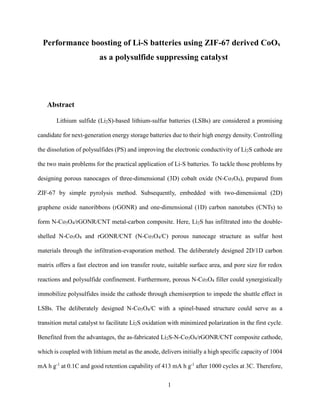
  • 23. 23 Figure 7. (a-b) Cyclic voltammograms at different scan rates, and (c-d) represents the plots of the peak current versus the square root of the scan rates for Li2S-rGONR/CNT and Li2S-N- Co3O4/rGONR/CNT electrodes. 3.5Rate Capability and Electrochemical Performance The two composite cathodes at various current densities ranging from 0.2 to 5C were used to examine the different C-rate profiles. Figure 8(a) shows that cells based on Li2S-N- Co3O4/rGONR/CNT cathode were delivered with average discharge capacities of 927, 853, 793, 690, and 624 mAh g-1 at current rates from 0.2 0.5, 1, 3, and 5C stepwise, and come back to 0.2C,
  • 24. 24 respectively, assigning to a 92% capacity retention. Concurrently, the cell based on Li2S- rGONR/CNT cathode rapidly declined from 853, 772, 701, 588, and 517 mAh g-1 at current rates of 0.2, 0.5, 1, 3, and 5C, respectively, and gives 88% capacity retention when returning to 0.2C. The specific discharge capacity for the cells based on Li2S-N-Co3O4/rGONR/CNT at a low to high current rate (0.2~5C) was increased by 8%, 10%,13%,17%, and 21%, as compared to that of the cell based on Li2S-rGONR/CNT. Overall, the higher capacity retention of Li2S-N- Co3O4/rGONR/CNT, it is due to 3D porous N-Co3O4 nanocage fillers. They can assist the rapid conversion reaction rate, maintaining the structural stability of the cathode at high C-rates. Consequently, the cell based on N-Co3O4/C-modified composite has a high Li+ diffusion coefficient and is primarily responsible for the increased discharge capacity and greater kinetic reversibility after a high current rate. The respective charge/discharge curve is attached in Figure S5. To further investigate the long-term cycling performance of the two cells was evaluated at 1C/1C at room temperature. The initial coulombic efficiency of the cell based on Li2S-N- Co3O4/rGONR/CNT is approximately 93%, which is higher than that of the cell based on Li2S- rGONR/CNT composite (86%), as shown in Figure S6. This implies that the high utilization of sulfur occurs in the first cycle. Figure 8(b) illustrates the cell based on Li2S-N- Co3O4/rGONR/CNT provided the highest initial specific capacity of 786 mAh g−1 at 1C (1C = 1166 mA g−1 in our Li-S battery). The specific discharge capacity was maintained at 500 mAh g−1 with stabilized coulombic efficiency of 99% and slow capacity decay of 0.045% per cycle after 800 cycles. In contrast, the cells based on Li2S-rGONR/CNT exhibited initial specific capacities of 703 mAh g-1 at 1C, respectively; however, these were reduced to approximately 313 mAh g-1 after 800 cycles. Moreover, rapid fading was observed during the long-term cycling of the cells
  • 25. 25 based on Li2S-rGONR/CNT composite. This was possibly due to the migration of LiPSs through the separator and reduced as irreversible loss of Li2S, which may result in a more severe LiPSs shuttling effect. The cell based on Li2S-N-Co3O4/rGONR/CNT at 1C/1C exhibited a higher specific capacity with gradual fading during charge/discharge. The doubled-shell N-Co3O4/C design assisted in suppressing the polysulfide migration during cycling. This may be attributed to the good surface area and active sites to store and reuse the dissolved LiPSs, which extends cycling life. The Nyquist plots of the aged cells based on Li2S-N-Co3O4/rGONR/CNT and Li2S- rGONR/CNT cathodes after cycling at 1C/1C for 800 cycles. Two semicircles (RSEI and Rct) and Warburg diffusion impedances (W0) were observed in Figure S7. The values are listed in Table S1. The SEI layer of the cells based on Li2S-N-Co3O4/rGONR/CNT was compact and stable (it showed lower RSEI value of 1.5–3 ; see Table S1), which can maintain stable Li+ ion transport. However, the difference between the respective resistances of the cells based on Li2S-N- Co3O4/rGONR/CNT was limited, indicating that the conducting outer layer containing rGONR/CNT particles did not increase the internal resistance at the interface. Comparatively, the increase in resistance of the cells based on Li2S-rGONR/CNT may be due to unstable SEI characteristics after prolonged cycling. 3.5.1 Higher Current Rates and Long-Term Cycling Investigation The remarkable performance of Li2S-N-Co3O4/rGONR/CNT cathodes was evaluated under various conditions to establish their viability for the practical application of Li-S batteries. In half-cell, Li2S-N-Co3O4/rGONR/CNT cathode paired with Li foil shows an extremely stable cycling behaviour at a 3C rate (1C = 1166 mA g-1 ) with an impressive lifespan of over 1000 cycles in Figure 8(c). The mass loading of Li2 S is ca. 1.5 mg cm-2 assembled with an electrolyte/Li2S
  • 26. 26 ratio of 37 μL mg-1 . It should be noted that the cell based on Li2S-rGONR/CNT cathode can only deliver 413 mA h g-1 after 1000 cycles. This difference in the cycling performance between Li2S- N-Co3O4/rGONR/CNT and Li2S-rGONR/CNT cathodes reaffirm the supremacy of N-Co3O4/C fillers in Li-S cells. Also, the average coulombic efficiency of the cell based on Li2S-N- Co3O4/rGONR/CNT is much higher than that of the cell based on Li2S-rGONR/CNT. This reveals that polysulfide shuttling is suppressed via the N-Co3O4/C porous structure fillers in a cathode. After 500 cycles, lower coulombic efficiency and fast capacity fading were observed during the long-term cycling of the cells based on Li2S-rGONR/CNT. This was possibly due to the electrolyte used in LSBs that may decompose during cycling. This results in the formation of passivation layers on the electrode surface or the generation of insoluble reaction side products, both of which can adversely affect the high-rate electrochemical performance.
  • 27. 27 Figure 8. (a) The rate capabilities for the cells based on Li2S-rGONR/CNT and Li2S-N- Co3O4/rGONR/CNT composites from 0.2 to 5C rates, Long-term cycling performances of the cells based on Li2S-rGONR/CNT and Li2S-N-Co3O4/rGONR/CNT composites at (b) 1C/1C for 800 cycles at RT, (c) 3C/3C for 1000 cycles at RT. 3.5.2 Structural Evolution of Cycled Electrodes and Separators
  • 28. 28 After long cycling (at 1C/1C for 800cycles), inspect the electrode stability of bare and cycled electrodes by using an SEM image. Figures S8(a) and (d) show the untreated Li2S-N- Co3O4/rGONR/CNT and Li2S-rGONR/CNT composite cathodes show smooth surfaces and are well coated on Al foil. During cycling, porous interconnected structures facilitate the fast insertion and de-insertion of Li+ ion. After 800 cycles, cracking and agglomeration observed in the aged Li2S composite electrode were observed, indicated by the red circle in Figure S8(b-c) and S8(e- f), possibly owing to the impact of the severe LiPSs shuttering reactions. In Li2S-N- Co3O4/rGONR/CNT electrode shows a smooth surface with no agglomeration. This demonstrates that the N-Co3O4/C modified composite cathode exhibited excellent structural stability during the charge-discharge process, with no evident cracks found even after 800 cycles at a high current density of 1C, as compared to the 2D rGONR/1D CNT modified composite cathode. Figure S9(a-d) shows the SEM surface morphologies of the aged PP separators for Li2S- N-Co3O4/rGONR/CNT and Li2S-rGONR/CNT electrodes (after 800 cycles) at different magnifications. In Li2S-rGONR/CNT electrode, observe LiPS residues deposited on the surface of the aged PP separator, indicated yellow layer on a digital photo of the PP separator, shown in Figure S9(a-b). This blocked the pores of the PP separator, which affects the Li+ ion transport. This explained the capacity fading of the cycling cell and the active material loss after 800 cycles. In contrast, the morphologies of the Li2S-N-Co3O4/rGONR/CNT cathode with the cycled PP separator are shown in Figure S9(c-d), respectively. The aged PP separator exhibited a clean and uniform surface. No yellow layer on the separator surface was observed. This was attributed to the good catalytic property of the 3D porous N-Co3O4 fillers, which fasted up the LiPS conversion reaction and a better suppression of the shuttle effect during long-term cycling. 3.6Postmortem Analysis of Li Anode
  • 29. 29 The two cells containing Li foils were disassembled after 800 cycles and the surface morphology of the cycled Li anodes was examined using SEM. Figure 9(a-b) shows the SEM images of the cycled Li metal. The surface of the Li2S-rGONR/CNT-based cell with aged Li metal was rough and noticeable mossy Li dendrites in Figure 9(a). The rough surface exhibited a substantial surface area because of electrolyte decomposition and severe side reactions on the Li anode. These unfavorable side reactions resulted in an increase in the formation of dead Li, which caused an increase in overpotential; the thick aged Li anode was obtained. Conversely, the aged Li anode taken from the Li2S-N-Co3O4/rGONR/CNT-based cell maintained a smooth Li anode surface. The well interconnected structure of the N-Co3O4/C composite traps dissolved polysulfides to suppress Li dendrite growth on the anode side, as shown in Figure 9(b). Figure 9(c-d) displays a cross-sectional SEM image of the aged Li anode after 800 cycles. This was determined based on the increase in total Li anode thickness to ca. 459.6 μm, indicating the accumulation of many dead Li during charge/discharge as shown in Figure 9(c). In contrast, the aged Li anode from the Li2S-N-Co3O4/rGONR/CNT-based cell exhibited a smooth morphology devoid of mossy Li dendrite growth. The total thickness of the cycled Li anode was ca. 362.3 μm, as displayed in Figure 9(d). Compared to the Li2S-rGONR/CNT, the volume expansion of the aged Li anode from the Li2S-N-Co3O4/rGONR/CNT-based cell was suppressed. This may be due to the highly catalytic activity of the N-Co3O4 fillers, which can also prevent the migration of polysulfides.
  • 30. 30 Figure 9. (a-b) The top-view SEM images of the cycled Li metal anode, (c-d) The cross-sectional view SEM images of the cycled Li anode taken from Li2S-rGONR/CNT-based and Li2S- N-Co3O4/rGONR/CNT-based cells after 800 cycles, respectively. Table 1 lists the results from previous studies on Li2S-based S batteries and this study. The increase in specific discharge capacity of the Li2S-N-Co3O4/rGONR/CNT-based cell with PP separators was higher than that of the other studies. The reasons were due to the following: (1) the multiple interactions with LiPSs induced by N-Co3O4 fillers and nitrogen dopant allow highly active sites available to trap LiPSs. The high electronic conductivity generated by both 2D rGONR and 1D CNT carbon framework facilitates the transport of electrons during the conversion reaction. These two factors synergistic together result in excellent interfacial electrochemical kinetics; (2)
  • 31. 31 the presence of highly active sites in the MOF-derived (ZIF67) polar hosts are beneficial to accommodate sulfur and LiPSs. This can significantly improve electrochemical performances and assist in the long-term cycling stability of the cells; (3) rGONR/CNT acts as a physical sulfur reservoir or matrix, reducing the LiPSs dissolution into the electrolyte and maximizing the utilization of sulfur. As a result, the initial voltage barrier of the Li2S-N-Co3O4/rGONR/CNT composite is greatly alleviated, and the long cycling performance is distinctly enhanced. Table 1. Comparison studies of Li2S-based battery performance with literature data. Data Cathodes Separato r Li2S content (wt.%) Potential Barrier (V) High-rate capability (mAh g-1 ) Long-term cycling performance Capaci ty retenti on Refere nce Li2S/Ti3C2 PP 56 2.85 750@0.1C–360@2C 100 cycles@0.2C 60% 28 Li2S/p-C3N4/CNT PP 48 2.4 892@0.1C–501@2C 200 cycles@0.5C 600 cycles@2C 69% 56% 34 Li2S/Co@C PP 67.7 3.12 886@0.05C–148@3C 500 cycles@0.1C 33% 35 Li2S-Mo@C PP 47.7 2.51 821@0.2C–314@5C 70 cycles@0.1C 500 cycles@1C 68% 47% 36 Li2S/CNT/GO/PPy PP 64.7 2.52 857@0.2C–524@2C 400 cycles@2C 74% 37
  • 32. 32 Li2S-N- Co3O4/rGONR/CNT PP 61 2.39 927@0.2C–624@5C 800 cycles@1C 1000 cycles@3C 64% 65% Curre nt study 4. Conclusions In summary, we synthesized double-shelled N-Co3O4/C porous nanocage as Li2S host for Li-S battery. The Li2S-N-Co3O4/rGONR/CNT composite was successfully prepared and used as an electrode in Li2S-based batteries. Additionally, the N-Co3O4/C-based electrode significantly reduced the internal resistance due to the three-dimensional pathway provided by the double- shelled structure. Thus, the well interconnected micro/mesoporous structure of the Li2S-N- Co3O4/rGONR/CNT composites improved the Li+ ion diffusion coefficient and electron transport. The synergistic effect of the deliberately designed N-Co3O4/C porous structure was further tuned for Li-polysulfide immobilization. Along with this physical confinement, N-cobalt oxide nanocages exhibited both physical/chemical sequestration of polysulfides and acted as electrocatalysts to promote the conversion reaction kinetics. Moreover, our mixed hierarchical electrode design markedly enhanced Li2S active material utilization; however, it also immobilized LiPS migration to suppress dendrite formation. Consequently, the Li2S-based cell based on Li2S-N-Co3O4/rGONR/CNT exhibited a long lifespan of 800 cycles with a high reversible capacity of 500 mAh g-1 at 1C/1C.Acapacity retention of 64% and a capacity attenuation per cycle of only 0.045% were achieved. According to the high C-rate results, the combination of 3D N-doped cobalt oxide with 2D/1D carbon matrix can
  • 33. 33 synergistically improve the polysulfide confinement and electrochemical performance of Li-S batteries. It was found that the incorporation of the rGONR/CNT dual-carbon with 3D porous cobalt oxide fillers is a promising way for Li-S battery practical applications.
  • 34. 34 5. Reference (1) Manthiram, A.; Fu, Y.; Chung, S. H.; Zu, C.; Su, Y. S. Rechargeable lithium-sulfur batteries. Chem Rev 2014, 114 (23), 11751-11787. (2) He, J.; Chen, Y.; Li, P.; Fu, F.; Wang, Z.; Zhang, W. Three-dimensional CNT/graphene–sulfur hybrid sponges with high sulfur loading as superior-capacity cathodes for lithium-sulfur batteries. Journal of Materials Chemistry A 2015, 3 (36), 18605-18610. (3) He, J.; Chen, Y.; Lv, W.; Wen, K.; Xu, C.; Zhang, W.; Li, Y.; Qin, W.; He, W. From Metal- Organic Framework to Li2S@C-Co-N Nanoporous Architecture: A High-Capacity Cathode for Lithium-Sulfur Batteries. ACS Nano 2016, 10 (12), 10981-10987. (4) Li, Z.; Li, C.; Ge, X.; Ma, J.; Zhang, Z.; Li, Q.; Wang, C.; Yin, L. Reduced graphene oxide wrapped MOFs-derived cobalt-doped porous carbon polyhedrons as sulfur immobilizers as cathodes for high performance lithium sulfur batteries. Nano Energy 2016, 23, 15-26. (5) Zhang, K.; Xu, Y.; Lu, Y.; Zhu, Y.; Qian, Y.; Wang, D.; Zhou, J.; Lin, N.; Qian, Y. A graphene oxide-wrapped bipyramidal sulfur@polyaniline core-shell structure as a cathode for Li-S batteries with enhanced electrochemical performance. Journal of Materials Chemistry A 2016, 4 (17), 6404- 6410. (6) Fan, F. Y.; Carter, W. C.; Chiang, Y. M. Mechanism and Kinetics of Li2S Precipitation in Lithium-Sulfur Batteries. Adv Mater 2015, 27 (35), 5203-5209. (7) Seh, Z. W.; Wang, H.; Liu, N.; Zheng, G.; Li, W.; Yao, H.; Cui, Y. High-capacity Li2S–graphene oxide composite cathodes with stable cycling performance. Chemical Science 2014, 5 (4). (8) Sun, D.; Hwa, Y.; Shen, Y.; Huang, Y.; Cairns, E. J. Li2S nano spheres anchored to single- layered graphene as a high-performance cathode material for lithium/sulfur cells. Nano Energy 2016, 26, 524-532.
  • 35. 35 (9) He, J.; Chen, Y.; Lv, W.; Wen, K.; Xu, C.; Zhang, W.; Qin, W.; He, W. Three-Dimensional CNT/Graphene–Li2S Aerogel as Freestanding Cathode for High-Performance Li–S Batteries. ACS Energy Letters 2016, 1 (4), 820-826. (10) Yang, Y.; Zheng, G.; Misra, S.; Nelson, J.; Toney, M. F.; Cui, Y. High-Capacity Micrometer- Sized Li2S Particles as Cathode Materials for Advanced Rechargeable Lithium-Ion Batteries. Journal of the American Chemical Society 2012, 134 (37), 15387-15394. (11) Wu, F.; Lee, J. T.; Fan, F.; Nitta, N.; Kim, H.; Zhu, T.; Yushin, G. A Hierarchical Particle-Shell Architecture for Long-Term Cycle Stability of Li2S Cathodes. Adv Mater 2015, 27 (37), 5579- 5586. (12) Liu, H.; Zeng, P.; Li, Y.; Yu, H.; Chen, M.; Jamil, S.; Miao, C.; Chen, G.; Liu, Q.-C.; Luo, Z.; Wang, X. Polyaniline-Derived Carbon Heterostructure as Redox Mediator of Li2S Oxidation and Polysulfide Immobilizer for High-Performance Lithium–Sulfur Cathode. ACS Sustainable Chemistry & Engineering 2020, 8 (44), 16659-16670. (13) Li, X.; Gao, M.; Du, W.; Ni, B.; Wu, Y.; Liu, Y.; Shang, C.; Guo, Z.; Pan, H. A mechanochemical synthesis of submicron-sized Li2S and a mesoporous Li2S/C hybrid for high performance lithium/sulfur battery cathodes. Journal of Materials Chemistry A 2017, 5 (14), 6471- 6482. (14) Ye, H.; Li, M.; Liu, T.; Li, Y.; Lu, J. Activating Li2S as the Lithium-Containing Cathode in Lithium–Sulfur Batteries. ACS Energy Letters 2020, 5 (7), 2234-2245. (15) Ting, L. K. J.; Gao, Y.; Wang, H.; Wang, T.; Sun, J.; Wang, J. Lithium Sulfide Batteries: Addressing the Kinetic Barriers and High First Charge Overpotential. ACS Omega 2022, 7 (45), 40682-40700.
  • 36. 36 (16) Xu, J.; Zhang, W.; Chen, Y.; Fan, H.; Su, D.; Wang, G. MOF-derived porous N–Co3O4@N-C nanododecahedral wrapped with reduced graphene oxide as a high capacity cathode for lithium- sulfur batteries. Journal of Materials Chemistry A 2018, 6 (6), 2797-2807. (17) Li, Z.; Zhang, J.; Guan, B.; Wang, D.; Liu, L. M.; Lou, X. W. A sulfur host based on titanium monoxide@carbon hollow spheres for advanced lithium-sulfur batteries. Nat Commun 2016, 7, 13065. (18) Xia, S.; Zhou, Q.; Peng, B.; Zhang, X.; Liu, L.; Guo, F.; Fu, L.; Wang, T.; Liu, Y.; Wu, Y. Co3O4@MWCNT modified separators for Li-S batteries with improved cycling performance. Materials Today Energy 2022, 30. (19) Chen, T.; Ma, L.; Cheng, B.; Chen, R.; Hu, Y.; Zhu, G.; Wang, Y.; Liang, J.; Tie, Z.; Liu, J.; Jin, Z. Metallic and polar Co9S8 inlaid carbon hollow nanopolyhedra as efficient polysulfide mediator for lithium−sulfur batteries. Nano Energy 2017, 38, 239-248. (20) He, J.; Chen, Y.; Manthiram, A. Metal Sulfide‐Decorated Carbon Sponge as a Highly Efficient Electrocatalyst and Absorbant for Polysulfide in High‐Loading Li2S Batteries. Advanced Energy Materials 2019, 9 (20). (21) Zhou, L.; Li, H.; Wu, X.; Zhang, Y.; Danilov, D. L.; Eichel, R.-A.; Notten, P. H. L. Double- Shelled Co3O4/C Nanocages Enabling Polysulfides Adsorption for High-Performance Lithium– Sulfur Batteries. ACS Applied Energy Materials 2019, 2 (11), 8153-8162. (22) Sun, C.-L.; Chang, C.-T.; Lee, H.-H.; Zhou, J.; Wang, J.; Sham, T.-K.; Pong, W.-F. Microwave-Assisted Synthesis of a Core-Shell MWCNT/GONR Heterostructure for the Electrochemical Detection of Ascorbic Acid, Dopamine, and Uric Acid. ACS Nano 2011, 5 (10), 7788-7795.
  • 37. 37 (23) Kosynkin, D. V.; Higginbotham, A. L.; Sinitskii, A.; Lomeda, J. R.; Dimiev, A.; Price, B. K.; Tour, J. M. Longitudinal unzipping of carbon nanotubes to form graphene nanoribbons. Nature 2009, 458 (7240), 872-876. (24) Sun, F.; Wang, J.; Chen, H.; Li, W.; Qiao, W.; Long, D.; Ling, L. High efficiency immobilization of sulfur on nitrogen-enriched mesoporous carbons for Li-S batteries. ACS Appl Mater Interfaces 2013, 5 (12), 5630-5638. (25) Gu, M.; Wang, J.; Song, Z.; Li, C.; Wang, W.; Wang, A.; Huang, Y. Multifunctional Asymmetric Separator Constructed by Polyacrylonitrile-Derived Nanofibers for Lithium-Sulfur Batteries. ACS Appl Mater Interfaces 2023. (26) Wang, Y.; Li, X.; Wu, L.; Tan, J.; Liu, G.; Ye, C.; Ma, L.; Liu, Z.; Ye, M.; Shen, J. Highly lithiophilic and uniform Co-MOF-derived ultrathin Co3O4 nanoarrays enable dendrite-free lithium metal anode. Energy Storage Materials 2024, 66. (27) Wang, Q.; Ma, Y.; Wang, Z.; Liu, Z.; Xu, X.; Ma, Z.; Wang, Y.; Du, Y.; Lei, W. Blanket biochar loaded with nano-Co3O4/graphite heterostructure assisted polysulfide trapping for high-stability lithium sulfur batteries. Journal of Physics and Chemistry of Solids 2024, 188. (28) Liang, X.; Yun, J.; Xu, K.; Xiang, H.; Wang, Y.; Sun, Y.; Yu, Y. A multi-layered Ti3C2/Li2S composite as cathode material for advanced lithium-sulfur batteries. Journal of Energy Chemistry 2019, 39, 176-181. (29) Raj Deivendran, G.; Wu, S.-H.; Wu, Y.-S.; Chang, J.-K.; Jose, R.; Ng, K. H.; Poddar, M.; Sun, C.-L.; Yang, C.-C. Suppression of Polysulfides by Carbonized Polyacrylonitrile Modified Polypropylene Janus Separator for Li2S/r-GONR/CNT-Based Li–S Batteries. ACS Applied Energy Materials 2024.
  • 38. 38 (30) Wang, J.; Jia, L.; Duan, S.; Liu, H.; Xiao, Q.; Li, T.; Fan, H.; Feng, K.; Yang, J.; Wang, Q.; Liu, M.; Zhong, J.; Duan, W.; Lin, H.; Zhang, Y. Single atomic cobalt catalyst significantly accelerates lithium ion diffusion in high mass loading Li2S cathode. Energy Storage Materials 2020, 28, 375-382. (31) Jeyakumar, J.; Wu, Y.-S.; Wu, S.-H.; Jose, R.; Yang, C.-C. Surface-Modified Quaternary Layered Ni-Rich Cathode Materials by Li2ZrO3 for Improved Electrochemical Performance for High-Power Li-Ion Batteries. ACS Applied Energy Materials 2022, 5 (4), 4796-4807. (32) Tao, X.; Wang, J.; Liu, C.; Wang, H.; Yao, H.; Zheng, G.; Seh, Z. W.; Cai, Q.; Li, W.; Zhou, G.; Zu, C.; Cui, Y. Balancing surface adsorption and diffusion of lithium-polysulfides on nonconductive oxides for lithium-sulfur battery design. Nat Commun 2016, 7, 11203. (33) Chen, M.; Zhao, S.; Jiang, S.; Huang, C.; Wang, X.; Yang, Z.; Xiang, K.; Zhang, Y. Suppressing the Polysulfide Shuttle Effect by Heteroatom-Doping for High-Performance Lithium– Sulfur Batteries. ACS Sustainable Chemistry & Engineering 2018, 6 (6), 7545-7557. (34) Liang, S.; Chen, J.; Zhou, N.; Hu, L.; Liu, L.; Wang, L.; Liang, D.; Yu, T.; Tian, C.; Liang, C. CNT threaded porous carbon nitride nanoflakes as bifunctional hosts for lithium sulfide cathode. Journal of Alloys and Compounds 2021, 887, 161356. (35) Yang, H.; Lei, Y.; Yang, Q.; Zhang, B.-W.; Gu, Q.; Wang, Y.-X.; Chou, S.; Liu, H.-K.; Dou, S.-X. Cobalt-induced highly-electroactive Li2S heterostructured cathode for Li-S batteries. Electrochimica Acta 2023, 439, 141652. (36) Liang, S.; Dong, R.; Lu, S.; Hu, L.; Liu, L.; Dong, Q.; Deng, C.; Qin, G.; Xu, M.; Liang, C. Green synthesis of fig–like Li2S–Mo@C nanocomposites for advanced lithium–sulfur batteries. Electrochimica Acta 2022, 426.
  • 39. 39 (37) Liu, H.; Zeng, P.; Yu, H.; Zhou, X.; Li, Z.; Chen, M.; Miao, C.; Chen, G.; Wu, T.; Wang, X. Enhancing the electrochemical performances of Li2S-based cathode through conductive interface design and addition of mixed conductive materials. Electrochimica Acta 2021, 396, 139238.
  • 40. 40 Supporting Information Performance boosting of Li-S batteries using ZIF-67 derived CoOx as a polysulfide suppressing catalyst The total number of pages: 8 (S1-S8) The total number of Figures: 10 (Figure S1-Figure S10) The total number of Tables: 1 (Table S1) Figure S1. SEM images of ZIF-67 particles.
  • 41. 41 Figure S2. EDX mapping results of N-Co3O4 with the presence of elements N, Co, and O.
  • 42. 42 Figure S3. (a-b) display SEM images of Li2S-N-Co3O4/rGO/CNT composite material and (c) shows the cross-sectional images of Li2S-N-Co3O4/rGO/CNT cathodes.
  • 43. 43 Figure S4. EDX mapping results of Li2S-N-Co3O4/rGO/CNT composite with the presence of elements S, Co, C, and N. Figure S5. GCD voltage profiles of rate capability for (a) Li2S-N-Co3O4/rGO/CNT and Li2S- /rGO/CNT cathodes at various current densities from 0.2 to 2 C. Figure S6. GCD voltage profiles of long-term cycling performance for (a) Li2S-N- Co3O4/rGO/CNT and Li2S-/rGO/CNT cathodes at 1C rate for 800 cycles.
  • 44. 44 Figure S7. The EIS spectra of cells containing (a) Li2S-r-GO/CNT, (b) Li2S-N-Co3O4/r- GONR/CNT at 1C/1C after 800 cycles.
  • 45. 45 Figure S8. (a-c) The SEM images of fresh and cycled composite cathodes were taken from the cells containing (a-c) Li2S-r-GO/CNT after 800 cycles and (d-f) the cells containing Li2S-N-Co3O4/r-GO/CNT cathode.
  • 46. 46 Figure S9. The SEM images (a-b) separators taken from the cycled cell containing (a-b) Li2S-r- GO/CNT (c-d) Li2S-N-Co3O4/r-GO/CNT after 800 cycles at different magnifications of 5k and 10k; the inset: cycled OM images for both cathodes. Table S1. Rb, RSEI, Rct, Rt values of the Li2S-N-Co3O4/rGO/CNT|PP|Li and Li2S-rGO/CNT| PP|Li cells before and after 800 cycles. Battery system Before cycling Rb () RSEI () Rct () Rt () Li2S-rGO/CNT|PP|Li 2.1 - 30.5 32.6 Li2S-N-Co3O4/rGO/CNT|PP| Li 1.4 - 19.6 21.0
  • 47. 47 Battery system After 5 cycles Rb () RSEI () Rct () Rt () Li2S-rGO/CNT|PP|Li 2.8 8.0 12.0 22.8 Li2S-N-Co3O4/rGO/CNT|PP| Li 1.5 7.3 6.7 15.5 Battery system After 800 cycles Rb () RSEI () Rct () Rt () Li2S-rGO/CNT|PP|Li 7.5 3.2 9.3 20 Li2S-N-Co3O4/rGO/CNT|PP| Li 2.3 1.6 4.5 8.4 Note: Rt = Rb + RSEI + Rt. Table S2. Lithium-ion diffusion coefficient analysis of Li2S-rGO/CNT and Li2S-N- Co3O4/rGO/CNT composite, using the Randles-Sevcik equation: ipeak = 268,600 × e1.5 × area × coefficientLi-ion 0.5 × concentrationLi-ion × rate0.5 , where ipeak is the peak current, e is the number of electrons, area is the electrode area, concentrationLi-ion is the lithium-ion diffusion concentration in the electrolyte, and the rate is the scanning rate. concentrationLi-ion (cm2 S-1) a1 c1 c2 Li2S-rGO/CNT 5.34 × 10⁻⁶ 1.39 × 10⁻⁶ 1.05 × 10⁻⁶ Li2S-N-Co3O4/rGO/CNT 4.7 × 10⁻⁶ 8.33 × 10⁻⁷ 7.82 × 10⁻⁷