
Recommended
More Related Content
What's hot
What's hot (20)
Similar to Planos hidraulicos bocat cat
Similar to Planos hidraulicos bocat cat (20)
Recently uploaded
Recently uploaded (20)
Planos hidraulicos bocat cat
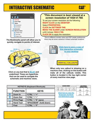
- 1. Click here to view the Schematic Symbols and Definitions page INTERACTIVE SCHEMATIC The Bookmarks panel will allow you to quickly navigate to points of interest. Click on any text that is BLUE and underlined. These are hyperlinks that can be used to navigate the schematic and machine views. When only one callout is showing on a machine view, clicking on this button will make all of the callouts visible. This button is located in the top right corner of every machine view page. VIEW ALL CALLOUTS Cover Page Tables Schematic Machine Views Component Connector Chassis View Cab View Engine View Features Options Bookmarks X EC-C3 EC-C2 E-C60 EC-C1 E-C61 To set your screen resolution do the following: RIGHT CLICK on the DESKTOP. Select PROPERTIES. CLICK the SETTINGS TAB. MOVE THE SLIDER under SCREEN RESOLUTION until it shows 1024 X 768. CLICK OK to apply the resolution. *This document is best viewed at a screen resolution of 1024 X 768. *Due to different monitor sizes and PDF reader preferences there may be some variance in linked schematic locations FUNCTION Zoom In HOTKEYS (Keyboard Shortcuts) Zoom Out Fit to Page Hand Tool “CTRL” / “+” KEYS “CTRL” / “-” “CTRL” / “0” (zero) “SPACEBAR” (hold down) Find “CTRL” / “F” Pressure Switch Temperature Switch Level Switch Flow Switch Circuit Breaker T ELECTRICAL SYMBOLS Spring (Adjustable) Variability Fluid Conditioner Pump or Motor BASIC HYDRAULIC COMPONENT SYMBOLS Click here to save a copy of this interactive schematic to your desktop
- 2. SCHEMATIC SYMBOLS AND DEFINITIONS HYDRAULIC SYMBOLS - ELECTRICAL Transducer (Fluid) Transducer (Gas / Air) G Generator Electrical Wire Pressure Switch M Electric Motor Pressure Switch (Adjustable) Temperature Switch Pressure Switch Temperature Switch Level Switch Flow Switch Circuit Breaker T ELECTRICAL SYMBOLS Spring Control Valves Restriction Line Restriction (Fixed) 2-Section Pump MAIN AUX. Spring (Adjustable) Variability Line Restriction (Variable) Pressure Compensation Pump: Variable and Pressure Compensated Hydraulic Pneumatic Energy Triangles Fluid Conditioner Attachment Pump or Motor BASIC HYDRAULIC COMPONENT SYMBOLS Line Restriction Variable and Pressure Compensated Vented Pressurized Return Above Fluid Level Return Below Fluid Level FLUID STORAGE RESERVOIRS Pressure Temperature Flow MEASUREMENT Unidirectional Bidirectional ROTATING SHAFTS One Position Two Position Three Position Two-way Three-Way Four-Way ENVELOPES PORTS CONTROL Basic Symbol Spring Loaded Normal Position A B P T A B P T Shifted Position Infinite Position Shuttle Pilot Controlled VALVES CHECK Solenoid or Manual Solenoid and Pilot Solenoid and Pilot or Manual Solenoid Servo Thermal Detent COMBINATION CONTROLS T Fuse: A component in an electrical circuit that will open the circuit if too much current flows through it. Switch (Normally Open): A switch that will close at a specified point (temp, press, etc.). The circle indicates that the component has screw terminals and a wire can be disconnected from it. Switch (Normally Closed): A switch that will open at a specified point (temp, press, etc.). No circle indicates that the wire cannot be disconnected from the component. Ground (Wired): This indicates that the component is connected to a grounded wire. The grounded wire is fastened to the machine. Ground (Case): This indicates that the component does not have a wire connected to ground. It is grounded by being fastened to the machine. Reed Switch: A switch whose contacts are controlled by a magnet. A magnet closes the contacts of a normally open reed switch; it opens the contacts of a normally closed reed switch. Sender: A component that is used with a temperature or pressure gauge. The sender measures the temperature or pressure. Its resistance changes to give an indication to the gauge of the temperature or pressure. Relay (Magnetic Switch): A relay is an electrical component that is activated by electricity. It has a coil that makes an electromagnet when current flows through it. The electromagnet can open or close the switch part of the relay. Solenoid: A solenoid is an electrical component that is activated by electricity. It has a coil that makes an electromagnet when current flows through it. The electromagnet can open or close a valve or move a piece of metal that can do work. Magnetic Latch Solenoid: An electrical component that is activated by electricity and held latched by a permanent magnet. It has two coils (latch and unlatch) that make electromagnet when current flows through them. It also has an internal switch that places the latch coil circuit open at the time the coil latches. BASIC ELECTRICAL COMPONENT SYMBOLS Push-pull Lever PedalGeneral Manual Push Button SpringManual Shutoff MANUAL CONTROL External Return Internal Return Simplified Complete Internal Supply Pressure RELEASED PRESSURE REMOTE SUPPLY PRESSURE PILOT CONTROL Spring Loaded Gas Charged ACCUMULATORS Crossing Joining LINES Double ActingSingle Acting CYLINDERS Unidirectional Bidirectional FIXED DISPLACEMENT VARIABLE DISPLACEMENT NON- COMPENSATED PUMPS Unidirectional Bidirectional Unidirectional Bidirectional FIXED DISPLACEMENT VARIABLE DISPLACEMENT NON- COMPENSATED MOTORS Unidirectional Bidirectional Two Position Infinite Positioning FLOW IN ONE DIRECTION FLOW ALLOWED IN EITHER DIRECTION Three Position CROSS FLOW PARALLEL FLOW INTERNAL PASSAGEWAYS 1 2 AG-C4 111-7898 L-C12 3E-5179 9X-1123 Component Part Number Pin or Socket Number Part Number: for Connector Plug Harness Identification Letter(s): (A, B, C, AA, AB, AC, ...) Plug 325-AG135 PK-14 Wire Color Wire Gauge Receptacle 1 1 2 2 Sure-Seal connector: Typical representation of a Sure-Seal connector. The plug and receptacle contain both pins and sockets. Deutsch connector: Typical representation of a Deutsch connector. The plug contains all sockets and the receptacle contains all pins. Fuse (5 Amps) 5A Harness identification code: This example indicates wire group 325, wire 135 in harness "AG". L-C12 3E-5179 Wire, Cable, or Harness Assembly Identification: Includes Harness Identification Letters and Harness Connector Serialization Codes (see sample). Harness Connector Serialization Code: The "C" stands for "Connector" and the number indicates which connector in the harness (C1, C2, C3, ...) HARNESS AND WIRE SYMBOLS
- 3. UENR4731 June 2013 Printed in U.S.A.© 2013 Caterpillar, All Rights Reserved 242D: A9W1-UP 262D: KTS1-UP 279D: PPT1-UP 246D: HMR1-UP 257D: EML1-UP 287D: STK1-UP 289D: WCT1-UP 236D: MPW1-UP 259D: GTK1-UP 277D: MLT1-UP 236D, 242D, 246D, and 262D Skid Steer Loader 257D, 277D, and 287D Multi-Terrain Loader 259D, 279D, and 289D Compact Track Loader Hydraulic System
- 4. COMPONENT TABLE Description Models Part Number Machine Location Schematic Location Accumulator GP All Models 227-8807 1 A-4 Accumulator GP - Ride Control All Models 310-8460 2 F-7 Breather - Hydraulic Tank All Models 258-2829 3 C-7 236D 378-0891 242D/257D/259D 380-5668 246D/277D/279D 375-7845 262D/287D/289D 377-9483 236D/242D/257D/259D 378-7964 246D/262D 358-5007 246D/262D/277D/279D/287D/289D 293-5712 236D/242D/257D/259D 378-7963 246D/262D 358-5007 246D/262D/277D/279D/287D/289D 293-5711 Filter AS - Hydraulic and Transmission Oil All Models 346-5576 7 F-11 388-7960 345-5165 Manifold GP - Pilot Shutoff (Two Speed) All Models 359-7222 B-4 Manifold GP - Ride Control All Models 345-4755 10 F-7 Motor GP - Hydraulic Man (Demand) All Models 258-2577 11 F-10 Motor GP - Hydraulic Fan (Standard) 236D/242D/257D/259D 307-3036 12 G-10 358-5009 358-5003 Motor GP - Hydrostat (Two Speed) (LH) 236D/242D 358-5011 14 E-15 Motor GP - Hydrostat (Two Speed) (RH) 236D/242D 358-5013 15 E-13 257D Only 373-8424 259D Only 373-8470 277D/279D/287D/289D 373-8422 279D/289D 373-8423 236D/242D/257D/259D 258-2405 All Other Models 341-7625 373-8426 358-5002 246D/262D/277D/279D/287D/289D 423-0086 236D/242D/257D/259D 358-5002 246D/262D/277D/279D/287D/289D 423-0086 299D XHP 341-7635 236D/242D/257D/259D 258-2555 All Other Models 358-5010 236D/242D/257D/259D 345-3609 All Other Models 345-3473 Strainer AS - Hydraulic Tank All Models 262-5689 21 C-8 Tank GP - Hydraulic All Models 345-4581 22 C-8 Valve GP - Check (Cooler Bypass) All Models 373-7039 23 A-15 Valve GP - Check (Ride Control) All Models 304-6756 24 E-7 All Models 373-6954 246D/262D/277D/279D/287D/289D 373-6956 Valve GP - Implement Control (High Flow) All Models 373-6959 26 H-6 Valve GP - Loader Arms Manual Lower All Models 112-1817 27 F-3 *If model is not listed that component will not be found on that machine Radiator and Hydraulic Oil Cooler GP 20 A-10 236D/242D/257D/259D All Models Motor GP - Hydrostat (One Speed) 13 I-14236D/242D Cylinder GP - Lift 4 F-3 Cylinder GP - Tilt (LH) 5 F-4 Fitting GP - Quick Coupler G-12 19 19 Pump GP - Hydrostat 17 A-13 Pump GP - Implement and Charge (Standard Flow) 18 Cylinder GP - Tilt (RH) 6 F-4 Valve GP - Implement Control (Standard Flow) 25 E-4 Component Locations Pump GP - Implement and Charge (High Flow) E-10 C-10Pump GP - Work Tool E-2 Motor GP - Hydrostat (Two Speed) B-10 8 9 16
- 5. TAP TABLE Tap Number Description Schematic Location AA Implement Pump Pressure D-5 AA Implement Pump Pressure G-3 EE Charge Pressure A-14 MA Main System Pressure (Pump 2 Reverse) A-13 MB Main System Pressure (Pump 2 Forward) C-13 MC Main System Pressure (Pump 1 Forward) C-14 MD Main System Pressure (Pump 1 Reverse) A-14 SOS Oil Sampling F-11 Tap Locations Pressure and Sampling
- 6. UENR4731 42Page,(Dimensions:56inchesx35inches) Components are shown installed on a fully operable machine with the key and engine off and with parking brake set. Refer to the appropriate Service Manual for Troubleshooting, Specifications and Systems Operations. SCHEMATIC PART NUMBER: 345-5170, CHANGE: 01, VERSION: - 259D, 279D, AND 289D COMPACT TRACK LOADER HYDRAULIC SYSTEM MEDIA NUMBER: UENR4731 Note: Refer to the Parts Manual using a specific serial number prefix in SIS before ordering parts from this schematic. 257D, 277D, AND 287D MULTI-TERRAIN LOADER THIS SCHEMATIC IS FOR THE 236D, 242D, 246D, AND 262D SKID STEER LOADER A B C D E F 1234567891011121314 G H I J A B C D E F G H I J 1516 12345678910111213141516 HYDRAULIC CIRCUIT COLOR DESCRIPTIONS PILOT PUMP OUTPUT MAIN PUMP OUTPUT TILT CYLINDER CIRCUIT CHARGE PUMP OUTPUT HYDRAULIC FAN CIRCUIT LOAD SENSE CIRCUIT SUPPLY LINE QUICK COUPLER CIRCUIT DRAIN / RETURN LINE STEERING CIRCUIT TRAVEL CONTROL CIRCUIT LIFT CYLINDER CIRCUIT LINE PATTERNS Drain / Return Lines Component Group Pilot / Load Sensing Pressure Pressure Line CALLOUTS Taps (Pressure, Sampling, Sensor - by letter)YY (52) VALVE GP - CONTROL 138-1234 Callout Number (Machine Location from Component LocationsTable) Component Name Part Number Air Line Tap Number Description Schematic Location AA Implement Pump Pressure D-5 AA Implement Pump Pressure G-3 EE Charge Pressure A-14 MA Main System Pressure (Pump 2 Reverse) A-13 MB Main System Pressure (Pump 2 Forward) C-13 MC Main System Pressure (Pump 1 Forward) C-14 MD Main System Pressure (Pump 1 Reverse) A-14 SOS Oil Sampling F-11 Tap Locations Pressure and Sampling STANDARD FAN DEMAND FAN RIDE CONTROL TWO SPEED HYDROSTAT MOTORS 236D/242D STANDARD FLOW HIGH FLOW TWO SPEED PILOT SHUTOFF STANDARD FLOW IMPLEMENT PUMP WORK TOOL PUMP TWO SPEED HYDROSTAT MOTORS 257D/259D/277D/287D/279D/289D/299D XHP ONE SPEED HYDROSTAT MOTORS 236D AND 242D AA AA EE MAMD MC MB SOS (17) PUMP GP HYDROSTAT (23) VALVE GP CHECK (COOLER BYPASS) (18) PUMP GP IMPLEMENT AND CHARGE (STANDARD FLOW) (19) PUMP GP WORK TOOL (20) RADIATOR AND HYDRAULIC OIL COOLER GP (21) STRAINER AS HYDRAULIC TANK (22) TANK GP HYDRAULIC (3) BREATHER HYDRAULIC TANK (1) ACCUMULATOR GP (7) FILTER AS HYDRAULIC AND TRANSMISSION OIL (12) MOTOR GP HYDRAULIC FAN (STANDARD) (11) MOTOR GP HYDRAULIC FAN (DEMAND) (10) MANIFOLD GP RIDE CONTROL (24) VALVE GP CHECK (RIDE CONTROL) (2) ACCUMULATOR GP RIDE CONTROL (27) VALVE GP LOADER ARMS MANUAL LOWER(5) CYLINDER GP TILT (LH) (6) CYLINDER GP TILT (RH) (4) CYLINDER GP LIFT (25) VALVE GP IMPLEMENT CONTROL (STANDARD FLOW) (14) MOTOR GP HYDROSTAT (TWO SPEED) LH (15) MOTOR GP HYDROSTAT (TWO SPEED) RH (9) MANIFOLD GP PILOT SHUTOFF (TWO SPEED) (16) MOTOR GP HYDROSTAT (TWO SPEED) (26) VALVE GP IMPLEMENT CONTROL (HIGH FLOW) QUICK COUPLER (8) FITTING GP QUICK COUPLER (13) MOTOR GP HYDROSTAT (ONE SPEED) 258-2405 (236D/242D/257D/259D) 341-7625 (ALL OTHER MODELS) 373-7039 (ALL MODELS) 373-8426 OR 358-5002 (236D/242D/257D/259D) 423-0086 (246D/262D/277D/279D/287D/289D) 258-2555 (236D/242D/257D/259D) 358-5010 (ALL OTHER MODELS) 345-3609 (236D/242D/257D/259D) 345-3473 (ALL OTHER MODELS) 262-5689 (ALL MODELS) 345-4581(ALL MODELS) 258-2829 (ALL MODELS) 227-8807 (ALL MODELS) 346-5576 (ALL MODELS) 307-3036 (236D/242D/257D/259D) 258-2577 (ALL MODELS) 345-4755 (ALL MODELS) 304-6756 (ALL MODELS) 310-8460 (ALL MODELS) 112-1817 (ALL MODELS) 378-7964 (236D/242D/257D/259D) 358-5007 (246D/262D) 293-5712 (ALL OTHER MODELS) 378-7963 (236D/242D/257D/259D) 358-5007 (246D/262D) 293-5711 (ALL OTHER MODELS) 378-0891 (236D) 380-5668 (242D/257D/259D) 375-7845 (246D/277D/279D) 377-9483 (262D/287D/289D) 373-6954 (ALL MODELS) OR 373-6956 (245D/262D/277D/279D/287D/289D) 358-5011 (236D/242D) 358-5013 (236D/242D) 359-7222 (ALL MODELS) 373-8424 (257D ONLY) 373-8470 (259D ONLY) 373-8422 (277D/297D/287D/289D) 373-8423 (279D/289D) 373-6959 (ALL MODELS) LIFT CYLINDERS LOADER ARMS MANUAL LOWER VALVE LH TILT CYLINDER RH TILT CYLINDER MBBAX7DCMC MAEMD L1 L3 I A Y R X CI CO L2 FO FI FmIFmO FmIFmO Pg T RT P H 1A 1B 2A 2B 3A 3B LS M P T B1 A1 L1L2 PPg T T0 Ls Pp A BA BA B XB B1 B1B M3 C D X7 A B I A Y R X C LOC C-14 D LOC C-14 X7 LOC C-13 A LOC C-13 B LOC C-13 STANDARD FAN DEMAND FAN STANDARD FAN DEMAND FAN WORK TOOL PUMP STANDARD FLOW IMPLEMENT PUMP WORK TOOL PUMP STANDARD FLOW IMPLEMENT PUMP WORK TOOL PUMP STANDARD FLOW IMPLEMENT PUMP TWOSPEEDHYDROSTATMOTOR(236D/242D) TWOSPEEDHYDROSTATMOTOR(OTHERMODELS) TWOSPEEDHYDROSTATMOTOR(236D/242D) TWOSPEEDHYDROSTATMOTOR(OTHERMODELS) STANDARDFAN DEMANDFAN XHP HIGH FLOW IMPLEMENT CONTROL VALVE STANDARD FLOW IMPLEMENT CONTROL VALVE XHP HIGH FLOW IMPLEMENT CONTROL VALVE STANDARD FLOW IMPLEMENT CONTROL VALVE XHPHIGHFLOW IMPLEMENTCONTROLVALVE STANDARDFLOW IMPLEMENTCONTROLVALVE XHPHIGHFLOWIMPLEMENTCONTROLVALVE STANDARD FLOW IMPLEMENT CONTROL VALVE STANDARD FLOW IMPLEMENT CONTROL VALVE XHP HIGH FLOW IMPLEMENT CONTROL VALVE STANDARD FLOW IMPLEMENT CONTROL VALVE XHP HIGH FLOW IMPLEMENT CONTROL VALVE XHPHIGHFLOW IMPLEMENTCONTROLVALVE STANDARDFLOW IMPLEMENTCONTROLVALVE XHP HIGH FLOW IMPLEMENT CONTROL VALVE STANDARD FLOW IMPLEMENT CONTROL VALVE 388-7960 (ALL MODELS) 345-5165 (ALL MODELS) 358-5003 OR 358-5009 (236D/242) L R X I 2 L R X I 2 C LOC C-14 D LOC C-14 X7 LOC C-13 A LOC C-13 B LOC C-13
- 8. REAR VIEW SOS MDMAEE 23 20 17 16 16 1211 7 VIEW ALL CALLOUTS
- 9. FRONT VIEW 19 18 13 8 6 5 VIEW ALL CALLOUTS