
Recommended
Recommended
More Related Content
What's hot
What's hot (20)
Similar to Esquema hidraulico d5 g
Similar to Esquema hidraulico d5 g (20)
Recently uploaded
Recently uploaded (20)
Esquema hidraulico d5 g
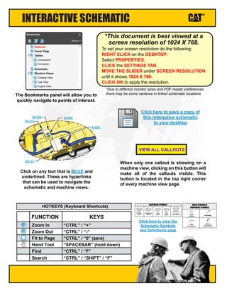
- 1. Click here to view the Schematic Symbols and Definitions page INTERACTIVE SCHEMATIC The Bookmarks panel will allow you to quickly navigate to points of interest. Click on any text that is BLUE and underlined. These are hyperlinks that can be used to navigate the schematic and machine views. When only one callout is showing on a machine view, clicking on this button will make all of the callouts visible. This button is located in the top right corner of every machine view page. VIEW ALL CALLOUTS Cover Page Tables Schematic Machine Views Component Connector Chassis View Cab View Engine View Features Options Bookmarks X EC-C3 EC-C2 E-C60 EC-C1 E-C61 To set your screen resolution do the following: RIGHT CLICK on the DESKTOP. Select PROPERTIES. CLICK the SETTINGS TAB. MOVE THE SLIDER under SCREEN RESOLUTION until it shows 1024 X 768. CLICK OK to apply the resolution. *This document is best viewed at a screen resolution of 1024 X 768. *Due to different monitor sizes and PDF reader preferences there may be some variance in linked schematic locations FUNCTION Zoom In HOTKEYS (Keyboard Shortcuts) Zoom Out Fit to Page Hand Tool “CTRL” / “+” KEYS “CTRL” / “-” “CTRL” / “0” (zero) “SPACEBAR” (hold down) Find “CTRL” / “F” Pressure Switch Temperature Switch Level Switch Flow Switch Circuit Breaker T ELECTRICAL SYMBOLS Spring (Adjustable) Variability Fluid Conditioner Pump or Motor BASIC HYDRAULIC COMPONENT SYMBOLS Click here to save a copy of this interactive schematic to your desktop Search “CTRL” / “SHIFT” / “F”
- 2. SCHEMATIC SYMBOLS AND DEFINITIONS HYDRAULIC SYMBOLS - ELECTRICAL Transducer (Fluid) Transducer (Gas / Air) G Generator Electrical Wire Pressure Switch M Electric Motor Pressure Switch (Adjustable) Temperature Switch Pressure Switch Temperature Switch Level Switch Flow Switch Circuit Breaker T ELECTRICAL SYMBOLS Spring Control Valves Restriction Line Restriction (Fixed) 2-Section Pump MAIN AUX. Spring (Adjustable) Variability Line Restriction (Variable) Pressure Compensation Pump: Variable and Pressure Compensated Hydraulic Pneumatic Energy Triangles Fluid Conditioner Attachment Pump or Motor BASIC HYDRAULIC COMPONENT SYMBOLS Line Restriction Variable and Pressure Compensated Vented Pressurized Return Above Fluid Level Return Below Fluid Level FLUID STORAGE RESERVOIRS Pressure Temperature Flow MEASUREMENT Unidirectional Bidirectional ROTATING SHAFTS One Position Two Position Three Position Two-way Three-Way Four-Way ENVELOPES PORTS CONTROL Basic Symbol Spring Loaded Normal Position A B P T A B P T Shifted Position Infinite Position Shuttle Pilot Controlled VALVES CHECK Solenoid or Manual Solenoid and Pilot Solenoid and Pilot or Manual Solenoid Servo Thermal Detent COMBINATION CONTROLS T Fuse: A component in an electrical circuit that will open the circuit if too much current flows through it. Switch (Normally Open): A switch that will close at a specified point (temp, press, etc.). The circle indicates that the component has screw terminals and a wire can be disconnected from it. Switch (Normally Closed): A switch that will open at a specified point (temp, press, etc.). No circle indicates that the wire cannot be disconnected from the component. Ground (Wired): This indicates that the component is connected to a grounded wire. The grounded wire is fastened to the machine. Ground (Case): This indicates that the component does not have a wire connected to ground. It is grounded by being fastened to the machine. Reed Switch: A switch whose contacts are controlled by a magnet. A magnet closes the contacts of a normally open reed switch; it opens the contacts of a normally closed reed switch. Sender: A component that is used with a temperature or pressure gauge. The sender measures the temperature or pressure. Its resistance changes to give an indication to the gauge of the temperature or pressure. Relay (Magnetic Switch): A relay is an electrical component that is activated by electricity. It has a coil that makes an electromagnet when current flows through it. The electromagnet can open or close the switch part of the relay. Solenoid: A solenoid is an electrical component that is activated by electricity. It has a coil that makes an electromagnet when current flows through it. The electromagnet can open or close a valve or move a piece of metal that can do work. Magnetic Latch Solenoid: An electrical component that is activated by electricity and held latched by a permanent magnet. It has two coils (latch and unlatch) that make electromagnet when current flows through them. It also has an internal switch that places the latch coil circuit open at the time the coil latches. BASIC ELECTRICAL COMPONENT SYMBOLS Push-pull Lever PedalGeneral Manual Push Button SpringManual Shutoff MANUAL CONTROL External Return Internal Return Simplified Complete Internal Supply Pressure RELEASED PRESSURE REMOTE SUPPLY PRESSURE PILOT CONTROL Spring Loaded Gas Charged ACCUMULATORS Crossing Joining LINES Double ActingSingle Acting CYLINDERS Unidirectional Bidirectional FIXED DISPLACEMENT VARIABLE DISPLACEMENT NON- COMPENSATED PUMPS Unidirectional Bidirectional Unidirectional Bidirectional FIXED DISPLACEMENT VARIABLE DISPLACEMENT NON- COMPENSATED MOTORS Unidirectional Bidirectional Two Position Infinite Positioning FLOW IN ONE DIRECTION FLOW ALLOWED IN EITHER DIRECTION Three Position CROSS FLOW PARALLEL FLOW INTERNAL PASSAGEWAYS 1 2 AG-C4 111-7898 L-C12 3E-5179 9X-1123 Component Part Number Pin or Socket Number Part Number: for Connector Plug Harness Identification Letter(s): (A, B, C, AA, AB, AC, ...) Plug 325-AG135 PK-14 Wire Color Wire Gauge Receptacle 1 1 2 2 Sure-Seal connector: Typical representation of a Sure-Seal connector. The plug and receptacle contain both pins and sockets. Deutsch connector: Typical representation of a Deutsch connector. The plug contains all sockets and the receptacle contains all pins. Fuse (5 Amps) 5A Harness identification code: This example indicates wire group 325, wire 135 in harness "AG". L-C12 3E-5179 Wire, Cable, or Harness Assembly Identification: Includes Harness Identification Letters and Harness Connector Serialization Codes (see sample). Harness Connector Serialization Code: The "C" stands for "Connector" and the number indicates which connector in the harness (C1, C2, C3, ...) HARNESS AND WIRE SYMBOLS
- 3. D3G: D4G: D5G: FDW1-UP FDH1-UP RKG1-UP WGB1-UP TLX1-UP CFN1-UP HYD1-UP FDC1-UP BYR1-UP JMH1-UP CFF1-UP CFC1-UP Hydraulic System D3G, D4G, and D5G Track-Type Tractor © 2016 Caterpillar All Rights Reserved CAT, CATERPILLAR, their respective logos, “Caterpillar Yellow”, and the POWER EDGE trade dress as well as corporate and product identity used herein, are trademarks of Caterpillar and may not be used without permission. March 2016 RENR7316-02
- 4. COMPONENT LOCATION Description Part Number Schematic Location Machine Location Block - Return Manifold 179-6053 I-11 1 Block Gp - Oil Cooler And Motor Bearing 175-5473 H-4 2 Block As - Suction Manifold 177-3572 I-8 3 Cooler Gp - Oil 317-4354 H-4 4 Cylinder Gp - Angle 259-0459 Cylinder Gp - Angle (Japanese) 264-8944 Cylinder Gp - Bulldozer Lift 183-3721 H-4, G-4 6 Cylinder Gp - Ripper (LH) 192-0893 E-12 7 Cylinder Gp - Ripper (RH) 192-0891 E-12 8 Cylinder Gp - Tilt 183-8459 H-3 9 Filter Gp - Oil (Winch Pump) 201-2744 G-10 10 Filter Gp - Oil (Rear pump) 196-1803 G-8 11 Filter Gp - Oil Transmission (SOS Valve) 212-9363 G-7 12 Test Gp - Pressure Test Remote Mounted (D3G) 174-5987 Test Gp - Pressure Test Remote Mounted (D4G , D5G) 221-9805 Manifold Gp 199-3475 E-5 14 Motor Gp - Piston (D4G,D5G,Right Motor) 169-2976 F-9 15 Motor Gp - Piston (D3G Left Motor) 214-6343 J-9 16 Motor Gp - Piston (D3G Right Motor) 214-6343 E-9 17 Motor Gp - Piston (55CC) 200-1729 A-8 18 Pump Gp - Implement 137-1296 Pump Gp - Implement (Japanese) 147-1057 Pump Gp - Double Piston (D4G,D5G Thru Drive) 215-9302 Pump Gp - Double Piston (D4G,D5G Without Thru Drive) 214-3243 Pump Gp - Double Piston (D3G Thru Drive) 236-4666 Pump Gp - Double Piston (D3G Without Thru Drive) 236-4667 Pump Gp - Piston (Winch) 178-4415 G-10 20 Screen - Suction 322-9703 I-11 21 Switch As - Pressure (Parking Brake) 201-4159 J-10 22 Tank Gp 194-3098 J-11 23 Valve (Shutoff) 4Y-3876 E-7 24 Valve Gp - Ball (Winch) 8T-6907 C-11 25 Valve Gp - Bank 3 (Power Beyond Grade Control) 243-3165 Valve Gp - Bank 3 (ST) 216-1633 Valve Gp - Bank 4 (ST) 216-1634 Valve Gp - Check Lift 9T-7634 F-6 27 Valve Gp - Check Ripper 9T-7634 F-7 28 Valve Gp - Control (Angle) 9T-7642 E-6 29 Valve Gp - Control (Lift) 199-3476 E-6 30 Valve Gp - Control (Tilt) 9T-7642 E-5 31 Valve Gp - Counterbalance 225-9596 D-4 32 Valve Gp - Flow Control 200-1311 A-10 33 Valve Gp - Grade Control Valve (Bank 2) 225-9595 C-1 34 Valve Gp - Line Relief (Ripper) 185-7709 F-6 35 Valve Gp - Main Relief 199-3478 E-5 36 Valve Gp - Pressure Relief 4T-4145 J-11 37 Valve Gp - Ripper (Auxiliary) 199-3477 E-7 38 Valve Gp - Shuttle 8J-6875 C-11 39 Valve Gp - Solenoid (Brake,Override) 200-6492 I-7 40 Valve Gp - Winch Logic Block 200-1309 D-10 41 Valve Gp - Winch Pilot 180-7339 D-11 42 Winch Group 179-9513 D-8 43 5 13 19 26 I-3, F-3 I-6 H-5 E-5 G-6 44
- 5. TAP LOCATION Tap Number Description Schematic Location AA Winch Pump - Case Drain Port G-10 BB Rear Pump - Case Drain Port G-9 CC Front Pump - Case Drain Port G-7 CL Hydraulic Oil Cooling Loop I-5 FCG Front Pump Charge Pressure I-5 IP Implement Pump Pressure I-5 LAB Front Pump Pressure Port I-5 M1 Winch Motor Control Pressure B-9 PB Parking Brake Pressure Port J-5 PC Rear Pump Drain Pressure Port I-5 RAB Rear Pump Pressure Port I-5 RCG Rear Pump Charge Pressure I-5 SOS Oil Sampling G-7 WAB Winch Pump Pressure Port I-6 WCG Winch Pump Charge Pressure I-6
- 6. Components are shown installed on a fully operable machine with the key and engine off, transmission shifter in neutral and with parking brake set. Refer to the appropriate Service Manual for Troubleshooting, Specifications and Systems Operations. SCHEMATIC PART NUMBER: 213-6413, CHANGE: 04, VERSION: - HYDRAULIC SYSTEM THIS SCHEMATIC IS FOR THE D3G, D4G, AND D5G TRACK-TYPE TRACTOR MEDIA NUMBER: RENR7316-02 Refer to the Parts Manual using a specific serial number prefix in SIS before ordering parts from this schematic. A B C D E F 1234567891011121314 G H I J 1234567891011121314 A B C D E F G H I J Attachment Air Line LINE PATTERNS Drain / Return Lines Component Group Pilot / Load Sensing Pressure Pressure Line CALLOUTS Taps (Pressure, Sampling, Sensor - by letter)YY Connectors (By letter)DL DL D HYDRAULIC CIRCUIT COLOR DESCRIPTIONS PILOT PUMP CHARGE CIRCUIT MAIN PUMP OUTPUT WINCH MOTOR CIRCUIT REAR PUMP CHARGE CIRCUIT STEERING CIRCUIT SUPPLY LINE BRAKE CIRCUIT ANGLE CYLINDER CIRCUIT LIFT CYLINDER CIRCUIT DRAIN / RETURN LINE WINCH PUMP CHARGE CIRCUIT TILT CYLINDER CIRCUIT RIPPER / AUXILLARY CYLINDER CIRCUIT WINCH CONTROL VALVE CIRCUIT WAB WCG CL PB RCG RAB FCG IP LAB SOS CC BB AA M1 PC WINCH ARRANGEMENT RIPPER RIPPER RIGHT MOTOR LEFT MOTOR FLUSHING VALVE FLUSHING VALVE LIFT LIFT ANGLE TILT ANGLE CCW X1X2AFAFEX1X2FE FA AY2 Y1 FEA FA WINCH PUMP S T R G G1 B MH PS CHRG R&R R&R POR ACTR S T R G G1 B MH PS PS1 R&R CHRG R&R POR ACTR CW CHRG R&R R&R POR ACTR S T R G G1 B MH PS PS1 CASE FILL BYPASS SWITCH A T U M1 B G A T U M1 B G CASE FILL BYPASS SWITCH Front Pump Case Fill BYPASS SWITCH RIPPER ANGLE LIFT TILT A B A A AB B B R R R R H H L L H L F H L FLOAT DETENT ENGINE AIR VENT-VACUUM MICRON AIR RELIEF TO GRADE CONTROL HYD. VALVE - TILT SECTION PLUG ENABLES POWER BEYOND MIN MAX P T 1 32 4 2 3 4 3 2 4 1 11 (DA) BRAKE F/S G T UXT B A (B) (FS)F/S BRAKE (2) (P) (Y) (4) R/OR/I FREE SPOOL BRAKE OFF REEL OUT REEL IN WINCH MOTOR CONTROL PRESSURE LIFT TILT A BA B PT LS M 9T-7642 179-9513 (D4G,D5G EP PUMP THRU DRIVE) - 215-9302 (D4G,D5G WITHOUT THRU DRIVE) - 214-3243 (D3G WITHOUT THRU DRIVE) - 236-4667 (D3G WITH THRU DRIVE) - 236-4666 194-3098 9T-7634 (18) MOTOR GP PISTON (55CC) 200-1729 (33) VALVE GP FLOW CONTROL 200-1311 (1) BLOCK RETURN MANIFOLD 179-6053 (7) CYLINDER GP RIPPPER (LH) 192-0893 (8) CYLINDER GP RIPPPER (RH) 192-0891 (3) BLOCK AS SUCTION MANIFOLD 177-3572 (44) PUMP GP - DOUBLE PISTON (24) VALVE (SHUTOFF) 4Y-3876 (38) VALVE GP RIPPER (AUXILIARY) 199-3477 (29) VALVE GP - CONTROL (30) VALVE GP - CONTROL LIFT 199-3476 (31) VALVE GP - CONTROL TILT 9T-7642 (14) MANIFOLD GP 199-3475 (36) VALVE GP MAIN RELIEF 199-3478 (26) VALVE GP BANK 3 : 216-1633 (ST) BANK 4 : 216-1634 (ST) BANK 3 : 243-3165 POWER BEYOND GRADE CONTROL (6) CYLINDER GP BULLDOZER LIFT 183-3721 (9) CYLINDER GP TILT 183-8459 (5) CYLINDER GP ANGLE (2 REQ) 259-0459 264-8944 (JAPANESE MACHINE) (5) CYLINDER GP ANGLE (2 REQ) 264-8944 (JAPANESE MACHINE) 259-0459 (28) VALVE GP (27) VALVE GP CHECK (LIFT) 9T-7634 (35) VALVE GP LINE RELIEF (RIPPPER) 185-7709 (12) FILTER GP OIL TRANSMISSION (SOS VALVE) 212-9363 (19) PUMP GP IMPLEMENT 137-1296 147-1057 (JAPANESE) (4) COOLER GP OIL 317-4354 (2) BLOCK GP OIL COOLER AND MOTOR BEARING 175-5473 (42) VALVE GP WINCH PILOT 180-7339 (25) VALVE GP BALL (WINCH) 8T-6907 (39) VALVE GP SHUTTLE 8J-6875 (41) VALVE GP WINCH LOGIC BLOCK 200-1309 (43) WINCH GROUP (23) TANK GP (21) SCREEN SUCTION 322-9703 (37) VALVE GP PRESSURE RELIEF 4T-4145 (22) SWITCH AS PRESSURE (PARKING BRAKE) 201-4159 (16) MOTOR GP PISTON 214-6343 (D3G EP) 169-2976 (D4G,D5G) (40) VALVE GP SOLENOID (BRAKE,OVERRIDE) 200-6492 (13) TEST GP PRESSURE TEST REMOTE MOUNTED 174-5987 (D3G) 221-9805 (D4G,D5G) (20) PUMP GP PISTON (WINCH) 178-4415 (10) FILTER GP OIL (WINCH PUMP) 201-2744 (11) FILTER GP OIL (REAR PUMP) 196-1803 (15) MOTOR GP 169-2976 (D4G,D5G) (17) MOTOR GP 214-6343 (D3G) (32) VALVE GP COUNTERBALANCE 225-9596 (34) VALVE GP BANK 2 : 225-9595 (GRADE CONTROL VALVE) ANGLE CHECK RIPPER Do not operate or work on this product unless you have read and understood the instruction and warnings in the relevant Operation and Maintenance Manuals and relevant service literature. Failure to follow the instruc- tions or heed the warnings could result in injury or death. Proper care is your responsibility. CALLOUTS (52) VALVE GP - CONTROL 138-1234 Callout Number (Machine Location from Component Locations Table) Component Name Part Number
- 7. CHASSIS VIEW CC 1 2 3 (Not Shown) 4 911 15 16 17 19 44 20 2122 23 25 26 32 3437 38 39 40 VIEW ALL CALLOUTS
- 8. FILTER GROUP 10 12 13 14 24 27 28 29 3031 35 36 42 AA CL FCGIP LAB PB PC RAB RCG WAB WCG CC SOS VIEW ALL CALLOUTS
- 9. RIPPER ARRANGEMENT 5 6 7 818 33 41 43 M1 VIEW ALL CALLOUTS