The document discusses Peerless dissolved gas flotation (DGF) systems, highlighting their design models (DGF-PQC and DGF-TFS) and operational efficiency in separating oil and solids from water. Utilizing a sophisticated pumping mechanism to generate micro-bubbles, these systems enhance separation performance and simplify traditional flotation processes. Benefits include improved contaminant removal, reduced operational costs, and a compact design suitable for various effluent characteristics.
![DISSOLVED GAS
FLOTATION
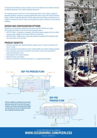
Typical General Arrangement for DGF-PQC model
[pressurised vessel design with four flotation cells].
Typical General Arrangement for DGF-TFS model
[covered atmospheric tank] in a single skid along
with chemical pre-treatment unit and DGF pumps.
PRODUCT APPLICATIONS
+ Produced water separation
+ Produced water injection
+ Refineries
+ Ship bilge and ballast water
PROCESS DESCRIPTION
Peerless Dissolved Gas Flotation units utilise a recirculation pump system to introduce
micro-bubbles, enhancing the separation surface area improving the oil and solid
separation performance.
The Peerless DGF has a sophisticated pumping mechanism to generate micro-bubbles.
These pumps utilize dual sided impellers to draw in vapour and precisely mix it with
the liquid. The vapour/liquid mixture is sheared and compressed in the pump to
enhance creation of micro-bubbles before this gas-enriched mixture is de-pressurized
and discharged to the flotation chamber. The dense bubble formation lifts oils and
solids to the liquid surface where they are ultimately skimmed off & discharged.
This configuration eliminates the need for a separate dissolution vessel as found on
many traditional dissolved air flotation systems. Further simplification is realised as
complicated back pressure and level control setups are no longer required.
PRINCIPLE OF OPERATION
In the Dissolved Gas flotation (DGF) process, the micro-size gas bubbles are generated
by saturating a pressurized partial stream of treated water with gas and subsequently
releasing this stream to atmospheric pressure.
This is contrary to the traditional process of Induced Gas Flotation, whereby gas is
drawn straight from the blanketing gas cap and is introduced into the raw water solely
by mechanical means such as impellers, jet nozzles or venturi devices.
DELIVERING CONFIDENCE IN CLEAN, SAFE AND EFFICIENT TECHNOLOGIES
© Peerless - OCTOBER 2017](https://image.slidesharecdn.com/peerless-dissolved-gas-flotation-240519234122-2c06eb2d/85/Peerless-Dissolved-Gas-Flotation-oil-water-separator-1-320.jpg)
![DISSOLVED GAS
FLOTATION
Typical General Arrangement for DGF-PQC model
[pressurised vessel design with four flotation cells].
Typical General Arrangement for DGF-TFS model
[covered atmospheric tank] in a single skid along
with chemical pre-treatment unit and DGF pumps.
PRODUCT APPLICATIONS
+ Produced water separation
+ Produced water injection
+ Refineries
+ Ship bilge and ballast water
PROCESS DESCRIPTION
Peerless Dissolved Gas Flotation units utilise a recirculation pump system to introduce
micro-bubbles, enhancing the separation surface area improving the oil and solid
separation performance.
The Peerless DGF has a sophisticated pumping mechanism to generate micro-bubbles.
These pumps utilize dual sided impellers to draw in vapour and precisely mix it with
the liquid. The vapour/liquid mixture is sheared and compressed in the pump to
enhance creation of micro-bubbles before this gas-enriched mixture is de-pressurized
and discharged to the flotation chamber. The dense bubble formation lifts oils and
solids to the liquid surface where they are ultimately skimmed off & discharged.
This configuration eliminates the need for a separate dissolution vessel as found on
many traditional dissolved air flotation systems. Further simplification is realised as
complicated back pressure and level control setups are no longer required.
PRINCIPLE OF OPERATION
In the Dissolved Gas flotation (DGF) process, the micro-size gas bubbles are generated
by saturating a pressurized partial stream of treated water with gas and subsequently
releasing this stream to atmospheric pressure.
This is contrary to the traditional process of Induced Gas Flotation, whereby gas is
drawn straight from the blanketing gas cap and is introduced into the raw water solely
by mechanical means such as impellers, jet nozzles or venturi devices.
DELIVERING CONFIDENCE IN CLEAN, SAFE AND EFFICIENT TECHNOLOGIES
© Peerless - OCTOBER 2017](https://image.slidesharecdn.com/peerless-dissolved-gas-flotation-240519234122-2c06eb2d/75/Peerless-Dissolved-Gas-Flotation-oil-water-separator-1-2048.jpg)