Downloaded 13 times


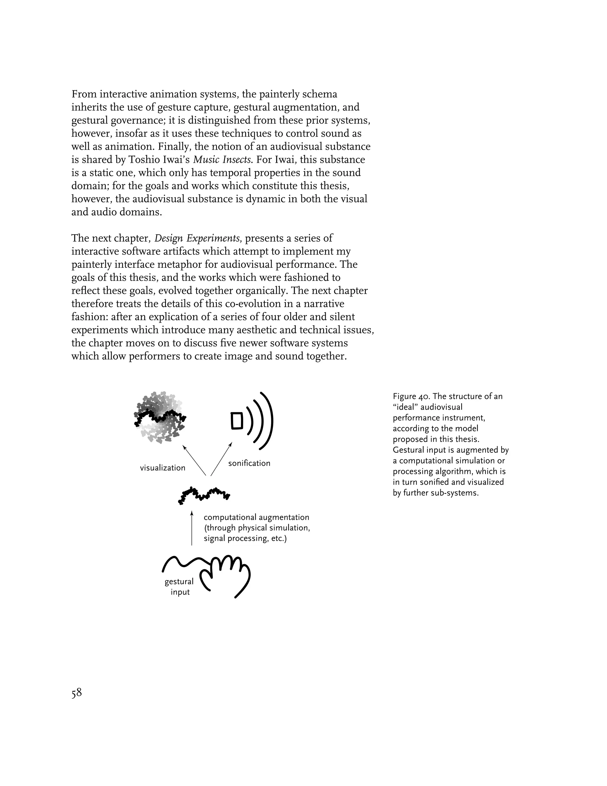
![1. Introduction
“In the impossibility of replacing the essential element of color by words or other means
lies the possibility of a monumental art. Here, amidst extremely rich and different
combinations, there remains to be discovered one that is based upon the principle
[that] the same inner sound can be rendered at the same moment by different arts.
But apart from this general sound, each art will display that extra element which
is essential and peculiar to itself, thereby adding to that inner sound which they
have in common a richness and power that cannot be attained by one art alone.”
—Wassily Kandinsky (1912)
1.1. Motivation
A few months ago the New York Times reported the discovery of a
9,000 year old bone flute in China. Remarkably enough, the flute
was still playable. As I listened in awe to sound files of the flute
that the Times had posted on the World Wide Web, I was struck
by an awareness that the human drive toward creative expression,
as it is realized through such vehicles as musical instruments and
drawing materials, must be among the oldest and most universal
of human desires.
This thesis seeks to fulfill our will to creative expression, by
making new expressions possible, and by advancing the state of
the art in our contemporary means. My focus is the design of
systems which make possible the simultaneous performance of
animated image and sound. I have chosen to implement these
systems by making use of the digital computer’s capacity to
synthesize graphics and sound in response to real-time gestural
inputs.
This work is important as it represents a vision for creative activity
on the computer, in which uniquely ephemeral dynamic media
blossom from the expressive signature of a human user. The
goal of this thesis is the design and implementation of a meta-
artwork—an artwork for creating artworks—whose interface is
supple and easy to learn, but which can also yield interesting,
inexhaustibly variable, and personally expressive performances in
both the visual and aural domains. In this thesis, I present several
examples of works which come close to this goal, by bringing two
things to bear on the problem space of audiovisual instruments:
firstly, flexible technologies, such as real-time audio synthesis,
gestural signal analysis, and expressive gestural interfaces; and
secondly, a systems aesthetic, which seeks to substantiate such
works with an underpinning of perceptual motivation, and infuse
such works with a vibrant collaboration between the system’s
designer and its performer.
17](https://image.slidesharecdn.com/painterlyinterfacesforaudiovisualperformance-110920201619-phpapp01/75/Painterly-interfaces-for-audiovisual-performance-17-2048.jpg)
![2. Background
The synchrony of abstract image and sound, variably known as
ocular music, visual music, color music, or music for the eyes,
has a history that spans several centuries of work by dozens of
gifted practitioners [Ritter 1993]. Despite the breadth and depth of
this history, however, a casual Web search reveals an unfortunate
ignorance of it, as numerous sites continue to advertise “an
entirely novel concept, relating graphics and music” or something
similar [Collopy 1999]. Adrien Bernard Klein, in his 1927 book
Color-Music: the Art of Light, deftly characterized this myopia: “It
is an odd fact that almost everyone who develops a color-organ is
under the misapprehension that he, or she, is the first mortal
to attempt to do so” [Klein 1927]. The absence of a ready
history of this domain can be partially explained by its frequent
association with the spiritual fringe, as well as the inability of
the art establishment to commodify such intangible work [Snibbe
and Levin 2000]. In this thesis I therefore present an extensive
introduction to this little-known background, motivated as much
by a desire to correct this myopia, as by a need to understand the
lessons of previous work.
This chapter divides the relevant background into three sections.
The first, Visual-Music Systems in the Pre-Computational Era,
examines a few of the most influential pre-computational
attempts to relate sound and image, across the domains of
performance instruments, abstract film, and optical sound-
synthesis. The second section, Visual Music in the Computational
Domain, examines the most prevalent schema by which sound
and image have been conventionally connected in the computer.
In the third section, A Painterly Interface for Visual Music, I
introduce a new metaphor for relating sound to image on the
computer, and discuss a handful of the most directly related
background examples.
2.1. Visual-Music Systems in the Pre-Computational Era
2.1.1. Color-Music Performance Instruments
2.1.1.1. Castel’s Ocular Harpsichord
The earliest known device for performing visual music was built
in 1734 by a Jesuit priest and mathematician, Father Louis-Ber-
trand Castel (1688-1757). Influenced by the writings of the 17th
Century Jesuit mystic Athanasius Kircher (1602-1680), Castel
21](https://image.slidesharecdn.com/painterlyinterfacesforaudiovisualperformance-110920201619-phpapp01/75/Painterly-interfaces-for-audiovisual-performance-21-2048.jpg)
![sought “to give the colours, irrespective of their harmonic order,
a kind of intensified quality of liveliness and lightness which they
inevitably lack upon a canvas without life or motion” [Popper
1968]. Castel’s Clavecin Oculaire coupled the action of a traditional
harpsichord to the display of transparent paper tapes, whose
colors were believed by Castel to correspond to the notes of the
Western musical scale.
Castel’s design consisted of a 6-foot square screen mounted above
a normal harpsichord. This frame was perforated by sixty small
windows, each containing a translucent colored tape, and each
covered by a mechanical shutter connected by pullies to each key
of the harpsichord. When a key was depressed, the shutter would
open, permitting candlelight to pass through one of the transpar-
ent tapes. An improved model, built in 1754, was designed for a
much larger audience and used some 500 candles with reflecting
mirrors. According to William Moritz, arguably the premiere his-
torian of color-music, Castel’s second instrument must have been
“hot, smelly and awkward, with considerable chance of noise and
malfunction between the pulleys, curtains and candles”) [Moritz
1997]. Castel described his “Ocular Harpsichord” in two essays
that were subsequently translated and annotated by the contempo-
rary German composer Georg Philipp Telemann [Peacock 1988].
“What stranger enterprise could be imagined in the whole field of
art,” wrote Castel, “than to make sound visible, to make available
to the eyes those many pleasures which Music affords to the
ears?”
Castel’s dream of a visible music hardly seemed strange to
the scores of artists, musicians, inventors and mystics he
served to inspire over the centuries which followed. Many of
these innovators adapted the basic design of Castel’s ocular
harpsichord, and in particular his use of a keyboard interface, as a
template for their own experiments. After Castel followed a steady
development of audiovisual instruments, employing a wide range
of technologies and materials: Frederic Kastner’s 1869 Pyrophone,
for example, opened flaming gas jets into crystal tubes to create
both sound and image [Popper 1968], while an 1877 device by
Bainbridge Bishop sat atop a pipe organ and produced light
with a high-voltage electric arc [Peacock 1988]. An instrument
patented by William Schooling in 1895 controlled the illumination
of variously-shaped vacuum tubes with a keyboard and set
of foot-pedals [Peacock 1988]. Other historic examples include
George Hall’s Musichrome (1930s), Morgan Russell and Stanton
Macdonald-Wright’s Kinetic Light Machine (1931), Gordon Pask
22](https://image.slidesharecdn.com/painterlyinterfacesforaudiovisualperformance-110920201619-phpapp01/75/Painterly-interfaces-for-audiovisual-performance-22-2048.jpg)
![and McKinnon Wood’s Musicolour machines (1953), and Jordon
Belson’s liquid-based instruments from the late 1950’s [Popper
1968, Peacock 1988, Moritz 1993]. These inventors and others are
treated individually and pictorially in Appendix A, A Timeline of
Instruments for Color-Music Performance.
The early Twentieth century was a phenomenal boom time in
the development of abstract visual performance systems. Buoyed
by advances in electric technology and optics, by the invention
of cinema, by the birth of modern perceptual psychology, and
by the rise of abstraction in Western visual art, dozens of new
systems were developed in the space of just a few decades.
Three Twentieth-century instruments deserve special attention
for their exceptionally high degree of aesthetic and technological
sophistication: Thomas Wilfred’s Clavilux, Oskar Fischinger’s
Lumigraph, and Charles Dockum’s MobilColor Projector. In
discussing them, we shall touch on design issues—such as
indirect versus gestural control, and the control of amorphous
versus geometric images—which continue to bear an impact in
the creation of today’s computational instruments.
One more theme which has cut across more than four centuries
of color-music research, from Castel’s to that of the present
day, is the question as to whether there are any “absolute”
correspondences between sound and vision. It is one of the
deepest issues in the field; some have felt that it is best answered
through empirical studies in psychology, while others have denied
the possibility of any essential mappings, and instead held that
the matter is simply an aesthetic one, best handled by design.
The truth is almost certainly somewhere in between. In the work
which follows, we will see a glimpse of how some of the Twentieth
century’s greatest color-music innovators dealt with the issue.
2.1.1.2. Thomas Wilfred’s Clavilux
Danish-born Thomas Wilfred came to America as a singer of early
music, and became involved with a group of Theosophists who
sought to build a color organ to demonstrate spiritual principles.
Initially, Wilfed sought an ‘absolute’ mapping between sound
and color as a way of exposing these principles. Having carefully
considered the work of his color-music predecessors, however,
and, noting their failures and divergences, come to the conclusion
Figure 1. A photograph of
a Clavilux projection. From that there was no absolute correspondence between color and
[Scattergood-Moore 1998]. sound, Wilfred instead turned his attention to an art of pure
light in which sound and music were either completely excluded
or admitted as mere accessories. He developed a color organ he
23](https://image.slidesharecdn.com/painterlyinterfacesforaudiovisualperformance-110920201619-phpapp01/75/Painterly-interfaces-for-audiovisual-performance-23-2048.jpg)
![called the Clavilux, and named the art form of its silent animated-
color projections “Lumia.” These Lumia, which emphasized the
use of slowly metamorphosing, polymorphous streams of fluid
color, stand as the earliest surviving color music about which we
can make fair aesthetic judgements [Popper 1968].
The first Clavilux was completed as early as 1919, and consisted
of “a large keyboard with five rows of sliding keys and stops that
could be coupled to obtain the colors; a battery of six principal
projectors and a certain number of grouped auxiliary reflectors.” Figure 2. A Clavilux
performance (date unknown).
Its design, according to Frank Popper, was very similar to an
organ with its pipes [Popper 1968]. Wilfred gave his first public
Clavilux recital on January 10, 1922, and thereafter began an
extensive tour of Clavilux concerts in the United States, Canada,
and Europe [Peacock 1988]. When he returned, Wilfred founded
the “Art Institute of Light” in New York City, where he installed
a 32-projector Clavilux in the Institute’s auditorium, and gave
two public Lumia recitals each week from November 1933 until
May, 1934 [Scattergood-Moore 1998]. In addition to his large
performance systems, Wilfred also constructed a variety of “Lumia
boxes,” self-contained units which could play for days or months
without repeating the same imagery [Moritz 1997], as well as a
small commercial run of “Home Clavilux” systems, which resem-
bled televisions but were designed for performance by consumer Figure 3. Wilfred’s Lumia Box
instrumentalists. and Home Clavilux used these
hand-colored glass disks to
produce a variety of light
effects [Scattergood-Moore
1998]. A similar technology was
independently developed by
Wladimir Baranoff-Rossiné for
his 1920 Piano Optophonique
[Baranoff-Rossiné 1997],
[Popper 1968].
Figure 4. Thomas Wilfred using
a Home Clavilux, c. 1930.
24](https://image.slidesharecdn.com/painterlyinterfacesforaudiovisualperformance-110920201619-phpapp01/75/Painterly-interfaces-for-audiovisual-performance-24-2048.jpg)
![Wilfred’s instruments and writings are important because they
give voice to an aesthetics of Lumia as integral art form in its
own right and with its own formal principles. In one article, for
example, Wilfred makes a point of differentiating the composition
and playing of Lumia from that of music. He thinks that the two
arts are so different that “attempts to design Lumia instruments
in imitation of musical ones will prove as futile as attempts to
write Lumia compositions by following the conventional rules laid
down for music.” He also argued that the rules governing static
composition and color harmony do not apply to form and color
in motion: “If a Lumia composition is stopped at any point, an
analysis of the static image may show both form and color out of
balance from the painter’s point of view.” [Wilfred 1947, 1948].
These issues are no less important today, and are at play, as we
shall see, in the works I have created to support this thesis; these
are discussed in Chapter 3.
2.1.1.3. Oskar Fischinger’s Lumigraph
In the late 1940’s the great abstract animator Oskar Fischinger
invented a color organ instrument that allowed one to play light.
According to William Moritz,
“[The] Lumigraph hides the lighting elements in a large frame, from
which only a thin slit emits light. In a darkened room (with a
black background) you can not see anything except when something
moves into the thin ‘sheet’ of light, so, by moving a finger-tip around
in a circle in this light field, you can trace a colored circle (colored
filters can be selected and changed by the performer). Any object can
be used: a gloved hand, a drum-stick, a pot-lid (for a solid circle), a
child’s block (for a square), etcetera” [ Moritz 1997].
The story of the Lumigraph’s genesis was recently retold by
Elfriede Fischinger, Oskar Fischinger’s widow:
“...A few days later, he called me down to his studio where he
had assembled what he called ‘The Light Instrument.’ The wooden
panels had become a box-like frame about 1 foot wide and 1 foot
deep. This ‘frame’ contained an opening that encased the latex sheet
mounted on a wooden canvas-support 3 feet high by 4 feet wide. The
colored gels had been fastened to glass strips that rotated on a wheel
inside the wooden frame-case, and a thin slit just inside the front
edge of the case only allowed the light from the (cool) neon tubes
inside the case to emerge at this one point to make a thin layer
of light in front of the rubber screen. This light slit was just far
enough in front of the screen so that only those portions of the
25](https://image.slidesharecdn.com/painterlyinterfacesforaudiovisualperformance-110920201619-phpapp01/75/Painterly-interfaces-for-audiovisual-performance-25-2048.jpg)
![Figure 5. The Lumigraph in
performance [Fischinger 1998].
screen that were pushed forward would fall into the path of the
light and become visible to the spectator sitting in front of the
instrument—and unless something did protrude into the thin light
layer, nothing would be visible at all! (The case was even painted
black). Each color of gel had been mounted on a different glass
strip, and these colored glasses could be rotated by pulling a canvas
strip on the back side of the case.... He placed a black curtain
behind the instrument, dressed entirely in black (long-sleeved turtle-
neck sweater, etcetera) but wore white gloves, so that only the
movements of his marvelously expressive hands would be visible,
floating mysteriously in the darkness. Our daughter, Barbara, still
remembers quite a bit of this, as she often worked the cords to
change the colors according to Oskar’s commands. For a smooth
public performance, it took two people to play the instrument—one
to perform the choreography of light, and one small, lithe person to
pull the cords to change the colors at given cues. When Oskar played
a piece like Sibelius’ ‘Valse Triste,’ he was very particular about the
colors, which had to be changed and mixed very precisely at exact
moments. Although the latex screen was opaque, Oskar arranged a
series of overhead mirrors so that he could see what the spectators
were watching out front [Fischinger 1998].
Unlike Thomas Wilfred, who rejected the possibility of
creating relationships between sound and image because of the Figure 6. Oskar Fischinger’s
Lumigraph was licensed for use
questionable psychological validity of any individual mapping, we in the 1960’s sci-fi film, The
can see from this narrative that Fischinger had an altogether Time Travelers.
26](https://image.slidesharecdn.com/painterlyinterfacesforaudiovisualperformance-110920201619-phpapp01/75/Painterly-interfaces-for-audiovisual-performance-26-2048.jpg)
![different view. For Fischinger, the possibility of a relationship
between sound and image, whether created with the Lumigraph
or for his abstract films, represented an opportunity for design.
However arbitrary such mappings might or might not be,
Fischinger’s own mappings were at the very least personal and
deliberate. His attitude toward sound-image mappings is a great
inspiration to my own work, described later in this thesis.
Fischinger performed the Lumigraph only a few times in public:
at the Coronet Theater in Los Angeles, and at the San Francisco
Museum of Art in 1953. The Lumigraph made brief appearances
in an Andy Williams television special, and in the 1964 science-
fiction movie The Time Travelers, in which it serves as a
“love machine” that allows people to vent their sexual urges
in a harmless sensuality [Moritz 1997]. According to Moritz,
Fischinger hoped, like Castel long before, that someone would
manufacture Lumigraphs, and that they would become common
household items, used by children for play and artistic training,
by adults for recreation and party games. Although that has not
yet occurred, Oskar’s original Lumigraph does survive, in the
Deutsches Filmmuseum in Frankfurt, where it is played with
some regularity [Moritz 1997].
Figure 7. A schematic diagram
of Fischinger’s Lumigraph,
from his 1955 patent for the
device [Fischinger 1955].
27](https://image.slidesharecdn.com/painterlyinterfacesforaudiovisualperformance-110920201619-phpapp01/75/Painterly-interfaces-for-audiovisual-performance-27-2048.jpg)
![The interaction design of Fischinger’s Lumigraph represents a
fundamentally important contrast to that of Wilfred’s devices:
Although both systems allowed a performer to perform patterns
of light, Wilfred’s Claviluxes produced visual displays according
to the remotely-controlled action of motorized mechanisms,
while Fischinger’s simple latex screen directly and immediately
conveyed the handmade and ephemeral markings of the
performer’s gestures. The space between “remote control” and
“direct control” is a blurry one, since any medium by its nature
interposes a material or process between its performer and its
product. Nevertheless, the degree to which a system provides
direct or indirect control is as much an issue in the design of
computational systems as it is in these physical examples.
2.1.1.4. Charles Dockum’s MobilColor Projector
Charles Dockum was a California inventor who began making
color organs in the late 1930’s. His motivation for doing so is
singularly interesting. According to William Moritz,
“Dockum suffered respiratory problems throughout his life, and
in his twenties came so close to death that he had the sort
of out-of body experience in which one’s spirit seems to detach
itself and fly off through cosmic realms...His urge to create mobile-
color projectors (console instruments for live performances of color
imagery) arose from his compulsion to recreate and communicate
his personal revelation.” [Moritz 1993].
Dockum developed a large projection system called the MobilColor
which allowed its performer to create temporal patterns of
moving, colored shapes. The dynamics of these patterns were
specified through a mechanical programming system, using
differently shaped cams. Although the MobilColor projector could
produce both hard-edged and soft-edged imagery, it did so
through the use of prepared image sources. The vocabulary of
its performances was therefore limited to translations, rotations,
colorizations and defocusings of these constituent image-units.
Both Oskar Fischinger and Charles Dockum received fellowships
from the Guggenheim Foundation through the Baroness Hilla
Rebay, who specified that each spy on the other to make sure that
he was really working on his grant project. Dockum’s grant went
into preparing a larger and more complex projector that would
allow multi-layered motion in several directions—a projector
destined for the Guggenheim Museum, since the rival Museum
28](https://image.slidesharecdn.com/painterlyinterfacesforaudiovisualperformance-110920201619-phpapp01/75/Painterly-interfaces-for-audiovisual-performance-28-2048.jpg)
![Figures 8 (left) and 9 (right). of Modern Art had a Thomas Wilfred Lumia on display. According
Charles Dockum with his to Moritz,
MobilColor Projector, and some
examples of the instrument’s
projected displays. “When Dockum installed the new MobilColor in the Guggenheim
Museum, the Baroness was shocked to learn that it required one
or two operators to perform it (whereas Wilfred had developed
automatic self-contained Lumia). The projector was consigned to
storage, and a few years later dismantled, with the light units used
for track-lighting in the galleries and the rest of the mechanisms
trashed. This meant that all of the compositions that Dockum
had created uniquely for that instrument were also effectively
destroyed—about 10 years’ work! The animator Mary Ellen Bute
shot a reel of documentary footage that preserves about 10 minutes
of short excerpts from Dockum’s performance on the Guggenheim
MobilColor, enough to show that it really did perform complex
layered imagery. Dockum spent the rest of his life, into the
mid-1970s, building another MobilColor, and composing about 15
minutes of material that can still be performed on it, at his old
studio in Altadena. While these compositions are brief, they show
three diverse types of imagery—geometric forms, vibrating dot
patterns, and soft sensuous trails—and above all demonstrate why
someone would want to go to all this trouble when film and slide
projections are so simple: the light intensity from the MobilColor
is quite simply astonishing, the vivid shapes and colors magically
hang in the darkness with a ‘living’ glow more ‘real’ than any image
projected through cinema” [Moritz 1993].
2.1.2. Abstract Film
Many other innovators designed optomechanical systems for
performing visual music; an extensive chronology of these
individuals and their instruments appears in Appendix A, A
Timeline of Instruments for Color-Music Performance. Some of these
29](https://image.slidesharecdn.com/painterlyinterfacesforaudiovisualperformance-110920201619-phpapp01/75/Painterly-interfaces-for-audiovisual-performance-29-2048.jpg)
![systems incorporated or produced both sound and light, such as
Castel’s Clavecin Oculaire or the machines of Kastner, Greenewalt,
Laszlo, Cross, Land, and Spiegel. Other designers, such as
Wilfred, Fischinger, Dockum, Bishop, Rimington, Baranoff-
Rossiné, Pesanek, and Klein, sought to explore the forms that a
visual analogy to music could take, and instead chose to construct
machines which were strictly intended for the performance of
dynamic visuals.
While these innovators developed “real-time” tools for the
performance of visual music, other pioneers composed elaborate
visual statements in the off-line laboratory of the animation
studio. Influenced by the twin births of cinema and visual
Modernism in the first two decades of the Twentieth century—
and possessing deeply held beliefs in a “universal language
of abstract form”—animators like Walter Ruttman, Viking
Eggeling, Oskar Fischinger, Len Lye, and Norman McLaren began
systematic studies of abstract temporal composition in order to
uncover “the rules of a plastic counterpoint” [Russett and Starr
1988]. Landmark events in abstract cinema included the 1921 Figure 10. Frames from Oscar
Frankfurt run of Ruttmann’s short Lichtspiel Opus I, thought Fischinger’s abstract film,
Radio-Dynamics (1938).
to have been the first screening ever of an abstract film for
a general audience [Russett and Starr 1988], and the 1924
release of Eggeling’s Diagonal Symphony, which was the first
entirely abstract film. By the late 1930’s, Oskar Fischinger had
established himself as the indisputable master of the form, having
invented or refined literally dozens of animation techniques.
The painstakingly constructed efforts of these and other artists
dramatically expanded the language and vocabulary of dynamic
visual form, at a time when the language of cinematic montage
itself was only beginning to be created and understood.
The history of abstract cinema is too great to describe here,
and has been extensively covered in, for example, [Russett and
Starr 1988], [Moritz 1993] and [Moritz 1997]. Nevertheless, it is
important to mention here that the visual languages developed
by the abstract animators have been a tremendous source of
inspiration to the work presented in this thesis. An example
of such an inspiration is the cinematic vocabulary developed
by the New Zealand animator Len Lye (active 1930-1960), who
explored “cameraless animation” techniques such as drawing,
scratching and painting directly on celluloid. Lye’s work vaults
Figure 11. Frames from Len
the gulf between the vitality of performance and the precision Lye’s abstract film, Free
of composition, for even though his movies were meticulously Radicals (1957).
constructed in his animation studio, his process of improvisation
30](https://image.slidesharecdn.com/painterlyinterfacesforaudiovisualperformance-110920201619-phpapp01/75/Painterly-interfaces-for-audiovisual-performance-30-2048.jpg)
![survives on-screen in frenetic and biomorphic works that are
a direct connection to his own experience, thought and mark-
making [Snibbe and Levin 2000].
2.1.3. Optical Soundtrack Techniques
Thus far we have focused on three important pre-computational
means for the production of animated visuals and audiovisual
compositions: color performance instruments, color-music sys-
tems, and abstract films. Our last stop in this section will be a
brief mention of the optical soundtrack techniques in which certain
filmmakers used entirely visual means to synthesize accompany-
ing sounds.
Once again, Oskar Fischinger was one of the earliest and
most masterful pioneers of the technique. Fischinger and his
assistants painted sound waveforms on long sheets of paper he
called “sound scrolls.” By photographically exposing the optical
soundtracks of the film to images of these scrolls, Fischinger was
able to create wholly synthetic music to accompany his animation.
Figure 12. Oskar Fischinger
with a “sound scroll” used in
the optical soundtrack of one
of his films.
While Fischinger drew individual waveforms by hand, the anima-
tor Norman McLaren, in Canada, developed a variety of template-
based methods. McLaren created and catalogued dozens of index
cards, each painted with a pattern of stripes whose spacings
produced notes in the chromatic scale. He would then mask
these stripes with cutout amplitude-envelope cards, in order to
produce sounds with differing attacks and decays (Figure 13) In
other experiments, McLaren dispensed with the cards and instead
masked regions of a special image from which McLaren could
produce any desired pitch (Figure 14).
31](https://image.slidesharecdn.com/painterlyinterfacesforaudiovisualperformance-110920201619-phpapp01/75/Painterly-interfaces-for-audiovisual-performance-31-2048.jpg)
![In the early 1950’s, the brothers John and James Whitney, a
pair of California animators, devised an unusual technique in
which “infrasonic pendulums” synthesized pure audio tones on
optical soundtracks. Using mechanical components salvaged from
decommissioned war machinery, the Whitneys constructed a
system of pendulums which would periodically interrupt the light
arriving at a film shutter. By slowly advancing the film past the
shutter while the pendulums swung back and forth, the Whitneys Figure 13. Norman McLaren
created these template cards
were able to expose periodic bands of darkness and lightness onto in order to generate sound
the film’s optical soundtrack. These bands would then produce “envelopes” in a film’s optical
audible sine tones when played back at a higher speed by the film soundtrack. Different shapes,
projector. By using multiple pendulums of varying lengths, the for example, produce sounds
with different length attacks
Whitneys were able to generate chords of different tones.
and decays. From [Russet and
Starr 1988].
Barry Spinello, an abstract animator active during the 1970’s, fol-
lowed in the footsteps of Fischinger, McLaren and the Whitneys
with a related optical soundtrack technique which made use of
Pres-Tone adhesive tapes. This material, also known as Ban-Day
dots, consists of adhesive strips with various densities and gra-
dations of half-tones printed on it, and was heavily used by
advertising and graphic designers prior to the birth of desktop
publishing. By assembling segments of Pres-Tone tapes into his
optical soundtracks, Spinello was able to achieve a variety of inter- Figure 14. Here, McLaren fills
esting sonic textures and effects, such as gurgling, hissing and an envelope template with a
grainy noises [Russet and Starr 1988]. Spinello’s technique is waveform of a specific pitch;
most notable for its contrast to those of his precursors, who the content of this envelope
seemed for the most part fixated on the synthesis of specific would then be photographed
onto the film’s optical
tones of precise frequencies. By shifting the level of granularity soundtrack. By sliding the
of his basic materials, Spinello was able to specify thousands template from left to right
of sound parameters with a single substance, thereby achieving across the converging stripes,
sounds which would be nearly impossible to produce by hand- McLaren was able to select
different pitches. Note how the
drawn means. His work is especially relevant to this thesis, for, as striped card has been marked
we shall see, his technique is essentially a type of “visual granular in solfege (i.e. Do-Re-Mi, etc.).
synthesis,” akin to the methods used in my Aurora (Section 3.2.4). From [Russet and Starr 1988].
The optical soundtrack techniques developed by these innovators
are important because they suggest a way in which visual patterns
can be used, not to represent sound, but to directly and physically
generate it: Although the optical drawings may be situated in a
scorelike timeline, the optical soundtrack is not a score whose
symbolic notations are read by a human, but an input to an
optoelectric machine which automatically renders them into
sound. This idea forms an important basis for the systems I
present in the next chapter, many of which employ mechanized
means for sonifying visual phenomena.
32](https://image.slidesharecdn.com/painterlyinterfacesforaudiovisualperformance-110920201619-phpapp01/75/Painterly-interfaces-for-audiovisual-performance-32-2048.jpg)
![2.2. Visual Music in the Computational Domain
2.2.1. Advantages of the computer for visual music
Physical color organs are burdened by an inherent trade-off
in their ability to yield specific versus general content [Snibbe
and Levin, 2000]. The control of detailed or precise images
requires a specificity of generative means, whereas the use of
highly general means tends to produce amorphous and difficult-
to-control results. To display the image of a triangle in the physical
world, for example, requires a triangular chip of transparent
material, or a triangular aperture—and that triangular element
can do little else but make triangles. By projecting light through
a tray of immiscible colored liquids, on the other hand, one can
produce an infinity of outcomes, but its inchoate and complex
results can be only vaguely directed. Computer technology has
made it possible for visual music designers to transcend the
limitations of physics, mechanics and optics, and overcome
the specific/general conflict inherent in electromechanical and
optomechanical visual instruments. One of the first artists to
take advantage of these means was the California filmmaker
John Whitney, who began his studies of computational dynamic
form in 1960 after twenty years of producing animations
optomechanically. Around the same time, Ivan Sutherland at MIT
developed SKETCHPAD, the first software to emulate the natural
process of drawing. Shortly thereafter, Myron Krueger made
some of the most fundamental developments in the connection
between interaction and computer graphics; his 1969 VideoPlace,
for example, used information from motion capture to direct
the animations of abstract forms [Krueger 1983]. PAINT, the
first generic paint program, was developed in the mid-1970’s
by Richard Shoup and Alvy Ray Smith. Since that time,
the expressive potential of real-time computer graphics have
burgeoned considerably.
At the same time, electronic and computer music has burgeoned
as well, spurred on by innovators eager to explore a realm of
sound similarly unbound by the laws of physics. The first (and
largest) synthesizer ever built was Thaddeus Cahill’s massive
electromechanical Telharmonium, built between 1897 and 1906.
The advent of the transistor hastened the development of more
lightweight “analog synthesis” techniques, developed by such
pioneers as Karlheinz Stockhausen and Iannis Xennakis in the
1950’s. The invention of the stored program electronic digital
computer in the 1940’s, however, truly opened the way for the
33](https://image.slidesharecdn.com/painterlyinterfacesforaudiovisualperformance-110920201619-phpapp01/75/Painterly-interfaces-for-audiovisual-performance-33-2048.jpg)
![present era of sound synthesis [Roads 1996]. Since the first
computational sound experiments of Max V. Matthews in 1957,
dozens of sound synthesis techniques have been invented. The
history of this field is vast, and is best left to other writers; it is
enough to note that as many innovators have developed unique
devices for composing, controlling and performing synthesized
sound, as have developed the sound synthesis techniques
themselves.
In the next sections, I discuss the ways in which the fields
of computer graphics and electronic music have been brought
together, with special attention to the paradigms of sound-image
relationships that have come to populate this intersection. In the
interests of space and precision, I have restricted myself to the
discussion of audiovisual computer systems that are specifically
intended for composition and/or performance.
2.2.2. Sound and the screen: strategies for sound/image
relationships on the computer
The majority of computer visual interfaces for the control
and representation of sound have been transpositions of
conventional graphic solutions into the space of the computer
screen. In particular, three principal metaphors for sound-image
relationships have come to dominate the field of visually-
orchestrated computer music: scores, control panels, and what I
term interactive widgets. In the next sub-sections, I treat each of
these strategies in turn, with special attention to the relationships
between sound and image which they use, and their applicability
to contexts of real-time performance.
2.2.2.1. Score Displays
Alan Kay once declared music notation to be one of the ten
most important innovations of the past millennium. Certainly it
is one of the oldest and most common means of relating sound
to a graphical representation. Originally developed by medieval
monks as a method for “hinting” the pitches of chanted melodies,
music notation eventually enabled a revolution in the structure
of Western music itself, making it possible for complex, large-
scale music to be performed, and yielding an attendant emergence
of new musical roles, hierarchies, and performance instruments
[Walters 1997]. Figure 15. An example of
standard music notation: the
first measure of M. Slonov’s “A
Mercy of Peace.”
34](https://image.slidesharecdn.com/painterlyinterfacesforaudiovisualperformance-110920201619-phpapp01/75/Painterly-interfaces-for-audiovisual-performance-34-2048.jpg)
![Scores are generally two-dimensional timeline diagrams which
operate by relating the dimension of time, along one axis, to some
other dimension of sound, such as pitch or amplitude, on the
other. In traditional music notation, there may be several parallel
time axes (called staves), which make possible the synchronization
of multiple simultaneous instrumentalists. In addition to Western
music notation, other common examples of sound-timelines are
waveform displays, player-piano scrolls, and spectrograms.
What these various sorts of timelines and diagrams share is a
reliance on a coded language of graphical conventions in order to
convey meaning. Once learned, this elaborate system of symbols
and visual relationships, refined by generations of composers and
typesetters, yields a remarkably efficient way of organizing and
producing a large quantity and variety of musical events [Walters
1997]. Naturally, many composers in search of further expressive
possibilities have experimented with alternative notation systems;
Figure 16. A page from the some, like Carmine Pepe (Figure 16), have invented idiosyncratic
score of Carmine Pepe’s Plastic
Containers, illustrating his use
and personal representations for various dimensions of sound.
of a personal and idiosyncratic Others, like Karlheinz Stockhausen or J. Levine, have partially
notation system. From [John- or wholly subverted the linear nature of the timeline itself. In
son 1978]. Stockhausen’s example below, the linear axis of time is no longer
measured in absolute units of seconds or beats, but instead
enumerates higher-level units (“events”) of musical organization.
Figure 17. Part of the score
from Karlheinz Stockhausen’s
Plus-Minus (1963). According
to John Walters, the symbols
used in the score are explained
in seven pages of detailed
instructions. “Each square
signifies a musical event and
the central open circle
represents a Zentralklang,
corresponding to one of eight
chords written on a separate
page” [Walters 1997].
35](https://image.slidesharecdn.com/painterlyinterfacesforaudiovisualperformance-110920201619-phpapp01/75/Painterly-interfaces-for-audiovisual-performance-35-2048.jpg)
![The score for J. Levine’s Parenthesis does away with the linearity Figure 18. The score for J.
of a timeline altogether; in its place, the score substitutes a Levine’s Parenthesis [Johnson
1978]. Note the extensive
two-dimensional lattice of events, each node of which offers sev- instructional key on the left.
eral subsequent event-possibilities in the squares adjacent to it.
Despite their visual beauty, it is imperative to observe that neither
of these examples can operate as a readable score without its
accompanying, and highly detailed, chart of symbolic keys.
Despite the investment necessary to learn written or graphic
languages of music notation, their use has become deeply
ingrained in the daily practice of an enormous number of
musicians around the world. The natural outcome of this is
that score-based systems now predominate the field of visually-
governed computer music. Thus the modern sequencer, the
workhorse tool of nearly every electronic composer, wraps the
functionality of a multi-track recording system around a backbone
of one or more editable timeline displays. Many such systems
now exist. Mark of the Unicorn’s Performer 6.0 sequencer, to
take a representative example, offers three different views of
musical information: standard music notation, digitized sound
waveforms, and MIDI notes displayed on a so-called “piano roll”
timeline [Mark of the Unicorn 2000].
36](https://image.slidesharecdn.com/painterlyinterfacesforaudiovisualperformance-110920201619-phpapp01/75/Painterly-interfaces-for-audiovisual-performance-36-2048.jpg)
![Figure 19. Two windows from
Mark of the Unicorn’s
Performer sequencer, showing
some of the available timeline Some software designers have attempted to innovate within
views for musical information the timeline schema by permitting users to edit data while the
in a typical sequencer [Mark of sequencer is playing the information in that timeline. This solution,
the Unicorn 2000]. which dramatically tightens the iteration cycle of composing
music, hybridizes the offline aspects of the sequencer’s notation
system with the real-time control of a performance instrument.
The Soundscapes musical instruments, created at the Interval
Research Corporation in 1995 in a project directed by Joy
Mountford, embody this idea. These instruments, which wrap
their timelines into one or more circles, were intended for the
creation and performance of cyclical music patterns. As the user
places markings around the perimeter of the circles, a current-
time indicator arm sweeps around in the manner of a radar
screen, triggering a MIDI event when it intersects one of the
Figure 20. Two of the Interval markings [Interval 1995]. Unfortunately, the visual interfaces
Soundscapes instruments: Web of the Soundscapes instruments have been so encrusted with
(left) and Shapes (right) decorative eye-candy that the underlying structure of their sound-
[Interval 1995]. A third image relationship has been nearly obscured by irrelevant graphic
instrument, Orbits, is not
pictured. information.
37](https://image.slidesharecdn.com/painterlyinterfacesforaudiovisualperformance-110920201619-phpapp01/75/Painterly-interfaces-for-audiovisual-performance-37-2048.jpg)
![Lukas Girling is a young British designer who has incorporated
and extended the idea of dynamic scores in a series of elegantly
spare but musically powerful interface prototypes. His Granulator
instrument, developed at Interval Research Corporation in 1997,
uses a stack of parallel looping timelines to control numerous
parameters of a granular synthesizer. Each panel in the Granula-
tor displays and controls the evolution of a different aspect of
the synthesizer’s sound, such as the strength of a lowpass filter
or the pitch of the sound’s constituent grains; users can draw
new curves for these timelines. One interesting innovation of the
Granulator is a panel which combines a traditional timeline with
an input/output diagram, allowing the user to interactively specify
the temporal evolution of a source soundfile’s playback location.
Figure 21. Lukas Girling’s
When diagrammatic instruments are allowed to go unconfected, Granulator interface [Girling
the relationship they establish between sound and image can 1998].
be extremely tight. Many individuals are able to read music
notation, or even speech spectrograms for that matter, as fluently
as they can read English or French. Nevertheless, it is essential to
remember that scores, timelines and diagrams, as forms of visual
language, ultimately depend on the reader’s internalization of a
set of symbols, signs, or grammars whose origins are as arbitrary
as any of those found in spoken language.
2.2.2.2. Control-Panel Displays
A second pattern which has come to predominate the design of
visual interfaces for electronic music is that of the control panel.
Designers who use this pattern have set about to imitate or evoke
the sound controls afforded by vintage analog synthesizers. These
synthesizers were typically manufactured during the 1970’s and
are immediately recognizable by the several dozen knobs, dials,
sliders and buttons which comprise their front panels. Analog
Figure 22. A Memorymoog
synthesizers have an almost legendary appeal, not only because
analog synthesizer, circa 1978.
of their unique sound and sometimes quirky behavior, but also
because their interfaces are completely laid bare, comprehensively
viewable, and enjoyably manipulable.
With the advent of digital synthesizers in the early 1980’s,
interfaces for controlling musical parameters in keyboard
synthesizers shifted from the use of directly-manipulable knobs,
to tiny alphanumeric LCD screens with nested menu systems.
While the digital synthesizers offered a wider range of sounds and
greater reliability than the older synthesizers, many musicians
38](https://image.slidesharecdn.com/painterlyinterfacesforaudiovisualperformance-110920201619-phpapp01/75/Painterly-interfaces-for-audiovisual-performance-38-2048.jpg)
![lamented the loss of the analog knobs they had found so ready-
at-hand, expressive and responsive. When speed improvements
in the mid-1990’s finally made it possible for desktop computers
to perform both professional-quality sound synthesis and color
graphics, devotees of the old analog synthesizers responded by
initiating a reactionary and nostalgic trend in synthesizer design:
the on-screen imitation of knob-laden control panels. Many of
the latest software synthesizers now resemble Koblo Software’s
Vibra6000, shown below.
Figure 23. The Vibra6000
software synthesizer for the
Macintosh, produced by Koblo
Software. The Koblo web site
advertises: “A knob for every
parameter! Forget about tiny
unreadable displays.” [Koblo
Software , 1999].
The Vibra6000’s use of instrumentally extraneous graphical
elements—that is to say, visual elements which have no musical
function—is modest by today’s standards. The most baroque of
the control-panel simulacra, as of this writing, is Propellerhead
Software’s ReBirth RB-338, designed specifically to imitate the
sound and appearance of the TB-303 Bass Line Synthesizer
originally manufactured by Roland Corporation in 1981. The
ReBirth RB-338 puts more than two hundred little knobs at
the control of the user’s mouse. The human propensities
for decoration and “personalization” being what they are, the
39](https://image.slidesharecdn.com/painterlyinterfacesforaudiovisualperformance-110920201619-phpapp01/75/Painterly-interfaces-for-audiovisual-performance-39-2048.jpg)
![Propellerhead designers have even made it possible for users to
wholly modify the graphic appearance (“skin”) of the RB-338:
“Here at Propellerhead we’re crazy enough to let users take our
precious ReBirth and redesign it any way they like. If you’re skilled
in graphic design and you have a bunch of cool drum samples
you’ve always wanted to share - make a modification, mail it to us
and maybe, just maybe, we will make sure it reaches every corner of
the world.” [Propellerhead Software, 1999].
Figure 24. Four variations of
the ReBirth RB-338 by
Propellerhead Software
[Propellerhead Software, 1999].
Users can modify the
appearance of the synthesizer
by substituting their own
bitmaps for the dials, buttons,
etc.
Unfortunately, graphic synthesizers which use the control-panel
schema replicate all of the undesirable aspects of multi-knob
interfaces—such as their bewildering clutter, their confusing
homogeneity, and their unobvious mapping from knobs to
underlying sound parameters—and none of their positive aspects,
such as their gratifying physical tactility, or their ability to be used
by multiple hands simultaneously. Furthermore, because identical
knobs are often assigned control of wholly dissimilar aspects
of sound, control-panel graphics share a disadvantage with
scores and diagrams: namely, that they must be “read” with
the aid of a symbolic or textual key. We can conclude our
discussion of control-panel displays, by observing that the ready
interchangeability of the synthesizer’s “skin” highlights the
extreme degree to which sound and image are disconnected in the
control-panel paradigm.
40](https://image.slidesharecdn.com/painterlyinterfacesforaudiovisualperformance-110920201619-phpapp01/75/Painterly-interfaces-for-audiovisual-performance-40-2048.jpg)
![2.2.2.3. “Interactive Widget” Displays
A third contemporary design pattern for screen-based computer
music is built on the metaphor of a group of virtual objects (or
“widgets”) which can be manipulated, stretched, collided, etc. by
a performer in order to shape or compose music. The foundation
of this schema is an assumption that “a sound can be abstracted
as an aural object” [Abbado 1988]. An application called Sounder
by Jack Freudenheim—described by its author, for better or for
worse, as a “musical lava lamp”—is a representative example of
a software system which embodies this idea [Perpetual Music
1994]. In this software, small abstract animating sprites bounce
around inside of a series of standard rectangular GUI windows.
Whenever an object collides with the boundary of its window
frame, it triggers a MIDI note on the computer’s soundcard.
Users can interact with Sounder by instantiating new sprites,
assigning pitches and timbres to them, “throwing” them in new
directions with the cursor, and modifying their periodic rhythms
by adjusting the dimensions of their containing windows.
Figure 25. Sounder by Jack
Freudenheim [Perpetual Music
1994].
Sounder is neither especially sophisticated in its visual design, nor
terribly expressive in its musical affordances, since the results
of its bouncing simulation are largely beyond the user’s control.
Lukas Girling’s Vector Field instrument, developed at Interval
Research Corporation in 1997, takes a step in the right direction
by allowing its users to exert precise control over the entire
trajectory of a flying widget. In Girling’s work, performers use the
41](https://image.slidesharecdn.com/painterlyinterfacesforaudiovisualperformance-110920201619-phpapp01/75/Painterly-interfaces-for-audiovisual-performance-41-2048.jpg)
![cursor to make modifications to the individual orientations and
intensities of the elements in a two-dimensional field of vectors.
These vectors then influence the flight path and spin of a
small autonomous cube, whose ballistic motions across the plane
are in turn mapped to certain control parameters (amplitude,
filter strength, resonance, etc.) of a digitally-sampled audio loop
[Girling 1998].
Figure 26. Lukas Girling’s
Vector Field interface [Girling
1998].
Users of Freudenheim’s Sounder and Girling’s Vector Field
are restricted to discrete adjustment operations instead of the
continuous, gestural operations which are typical of musical
performance. Sounder and Vector Field, moreover, largely adopt
an interaction model in which the user’s discrete manipulations
operate indirectly on the apparent agent of sound production:
instead of modifying a sonic widget itself, the user instead
manipulates some other property of the visual environment (such
as its boundary, or its terrain), which in turn exerts forces on the
sound-controlling widget.
Other designers, influenced by current work in “direct
manipulation” interfaces [Baecker 1995], or perhaps taking a cue
from the design of traditional, physical musical instruments, have
created “interactive widget” interfaces which are both gesturally
performable and directly manipulable. Reed Kram’s Transducer
software, created in 1997 in the Aesthetics and Computation
42](https://image.slidesharecdn.com/painterlyinterfacesforaudiovisualperformance-110920201619-phpapp01/75/Painterly-interfaces-for-audiovisual-performance-42-2048.jpg)
![group at MIT, implements this by permitting its users to
make continuous modifications directly to its cylindrical “Sound
Objects.” Kram describes his system thus:
“Transducer is a digital system for live, audio-visual performance....
Each sound clip is visualized as a ‘playable’ cylinder of sound that
can be manipulated both visually and aurally in real-time.... At first,
the system presents a palette of cylindrical objects. As the user
moves his or her mouse over each of the cylinders, he or she
hears a sampled sound stream associated with that object. Each
of the objects has a representative color and shape corresponding
to the sound stream associated with it... In this way a single
user or performer is able to build simultaneous visual and audio
constructions in realtime. The user can examine interrelationships
between multiple, diverse sound sources and a corresponding visual
form.” [Kram 1998].
Figure 27. An explanatory
diagram of the structure of the
Sound Objects used in Reed
Kram’s Transducer instrument
[Kram 1998].
43](https://image.slidesharecdn.com/painterlyinterfacesforaudiovisualperformance-110920201619-phpapp01/75/Painterly-interfaces-for-audiovisual-performance-43-2048.jpg)
![Transducer’s incorporation of extremely straightforward yet
arbitrary sound-image mappings, such as the relationship it
establishes between a cylinder’s height and a sound’s pitch, give it
a diagrammatic aspect not unlike the scores discussed previously.
In theory, this restricted set of mappings should make the system
easy to “read”; in reality, however, Transducer’s legibility is largely
impaired by two of Kram’s concomitant design choices: firstly,
pitch and amplitude in Transducer are not represented as absolute
quantities, but rather as ratios relative to a stored sound’s original
values. The effect of this is that samples which are heard at
identical pitches may be represented by cylinders of entirely
different heights, and vice versa. Secondly, Kram’s strategy of
representing all sounds as greenish-gray cylinders fails to generate
visual analogies to sound at the right level, or at enough levels,
of representation. It is impossible, for example, to distinguish the
Sound Object for a spoken vocal timbre, from a Sound Object for
a drum loop or a string section. The result is an instrument which Figure 28. Frames from Reed
substantially exchanges both musical legibility and visual interest Kram’s Transducer instrument
for a dubious graphic uniformity. in use. [Kram 1998].
An interesting contrast to this can be found in the Stretchable
Music software system developed by Pete Rice in the
Hyperinstruments group of the MIT Media Laboratory [Rice
1998]. In Rice’s work, each of a heterogeneous group of animated
graphical objects represents a track or layer in a pre-composed,
looping MIDI sequence. By gesturally pulling or stretching one of
these objects, a user can create a continuous modification to some
sonic property of a corresponding MIDI track, such as the filter
cutoff in a “square-wave” synthesizer melody, or the amount of
“breathiness” across a synthesized flute passage.
Figure 29. A screen capture
from Pete Rice’s Stretchable
Music system in use [Rice
1998].
44](https://image.slidesharecdn.com/painterlyinterfacesforaudiovisualperformance-110920201619-phpapp01/75/Painterly-interfaces-for-audiovisual-performance-44-2048.jpg)
![“interactive composition.” By inserting expressive handles into an
otherwise unchanging piece of music, Rice believes that he is able
to add “new levels of engagement to the continuum of musical
experience previously polarized into active performers and passive
listeners” [Rice 1998]. Although this is a worthwhile goal, Rice’s
system, and for that matter Girling’s Vector Field and Kram’s
Transducer, fail to use pre-recorded sound materials (and visual
materials) in such a way as to overcome their exhaustibility.
As a result these systems, while promising infinite possibilities,
become little more than mixing consoles for somebody else’s
tunes.
The most common disadvantage of “Interactive Widget” systems
is that their canned ingredients, all too inevitably, yield canned
results. The problem is fundamental and has to do with the
granularity of control such systems afford: in general, performance
systems whose interactions are predicated on the arrangement
or modulation of “high-level” sonic events (e.g. entire musical
passages and macrotemporal audio samples) and/or high-level
graphic phenomena (e.g. predefined geometries and images),
restrict users to performance experiences which are ultimately
exhaustible, or shallow, or both.
This section has dealt with the use of visual interfaces for
controlling sound on the computer. In the next section, I examine
a parallel trend in the recent history of visual music, namely the
ways in which the computer has been used to extend the tradition
of systems developed by Wilfred, Fischinger and Dockum—as a
performance medium for dynamic visuals.
2.2.3. Systems for Visual Performance on the Computer
The phrase “visual music” has enjoyed multiple meanings over
the last few centuries. For some artists and inventors, it has
referred to the products of a synæsthetic medium in which
complimentary sounds and visuals are combined into a holistic
unity. Examples of systems to which this understanding of the
term might apply are Castel’s Ocular Clavichord, the Interval
Soundscapes score-systems, and Pete Rice’s Stretchable Music
widget-system. Within the umbrella of “visual music,” however,
lurks a second interpretation which, interestingly enough, refers
to a strictly silent form. This understanding of “visual music”
has stood for the possibility of a dynamic, strictly visual
46](https://image.slidesharecdn.com/painterlyinterfacesforaudiovisualperformance-110920201619-phpapp01/75/Painterly-interfaces-for-audiovisual-performance-46-2048.jpg)
![medium whose temporal sophistication is equal to that of
traditional music. The silent, optoelectric and electromechanical
performance systems developed by Thomas Wilfred, Oskar
Fischinger and Charles Dockum were all designed with this latter
interpretation of “visual music” in mind. In this section of the
thesis, I examine some of the ways in which this silent form of
visual music has intersected with the affordances of computation.
The systems I discuss here all permit a user to gesturally create
and perform, in one way or another, pure, animated abstract
graphics. Of course, the space of all human gestures is much
vaster than the restricted and digitized set of movements to which
these systems respond. For the purposes of this discussion, and
for this thesis generally, I restrict my definition of the term
gesture to mean the combination of discrete and continuous
movements, deliberately performed by the hands, in relation to or
in combination with some markmaking medium or device.
Natural materials and media in the physical world excel at
transforming the traces of gesture into richly textured, expressive
marks. The computer’s low-resolution screen, by contrast—
physically displaced from the user’s hand and mouse—is a poor
subsitute. Nevertheless, the computer’s electronic display offers
unique affordances for gestural performance systems, such as
temporal dynamics, state transitions and conditional testing, and
models and simulations free from the traditional laws of physics.
As we shall come to see, the software applications discussed in
this section all use some form of gestural augmentation, based on
these affordances, to produce considerably expressive new media.
2.2.3.1. Paul Haeberli’s DynaDraw
In 1989, the graphics researcher Paul Haeberli developed
DynaDraw, a drawing program in which the user’s gestural
movements are augmented by an elastic physical simulation.
According to Haeberli,
“The program DynaDraw implements a dynamic drawing technique
that applies a simple filter to mouse positions. Here the brush is
modeled as a physical object with mass, velocity and friction. The
mouse pulls on the brush with a synthetic rubber band. By changing
Figure 30. Paul Haeberli’s
DynaDraw [Haeberli 1989]. the amount of friction and mass, various kinds of strokes can be
made. This kind of dynamic filtering makes it easy to create smooth,
consistent calligraphic strokes.” [Haeberli 1989]
47](https://image.slidesharecdn.com/painterlyinterfacesforaudiovisualperformance-110920201619-phpapp01/75/Painterly-interfaces-for-audiovisual-performance-47-2048.jpg)
![The chief contribution of DynaDraw is the idea that a user’s ink
can be augmented by a physical simulation. By interposing a virtual
spring between the user’s cursor and the nib of the virtual pen,
Haeberli creates dynamisms which are both startlingly fresh yet
comfortably familiar. In the process, he transforms a simple static
paint program into a wholly new medium whose products and
process are not only uniquely temporal, but are also evocative of
real-world behaviors.
2.2.3.2. John Maeda: Timepaint, A-Paint, and CMYK Dance
In the early 1990’s, John Maeda developed a series of
interactive software systems—Timepaint, A-Paint, and Process
Color Dance—to study the ways in which virtual “ink” could be
used to perform and display dynamic computations. Maeda’s
Timepaint is a delicate illustration of the dynamic process by
which apparently static marks are made: by extending our
view of a gesture’s temporal record into the third dimension,
Maeda’s work can flip between a flat animated composition and a
volumetric diagram of temporality. Maeda writes:
“Timepaint ... [presents] a time-lapse display of mouse motion as a
visual experience in two and a half dimensions. Multiple strokes can
be programmed and colored to produce wisp-like dynamic imagery
which fades into oblivion. Timepaint illustrates not just the lapse of
a single frame of time, but the continuum of time in which the
computer and user coexist” [Maeda 1995].
The kinds of animated compositions made possible by Timepaint
are highly constrained; all compositions, for example, are strictly Figure 31. Maeda’s Timepaint
[Maeda 1995].
composed of moving dots and their temporal trails. Although
this particular design decision places strict limits on what can be
expressed in the medium, it greatly enhances the effectiveness of
Maeda’s temporal visualization. In his A-Paint and Process Color
Dance, by contrast, Maeda instead emphasizes the affordances
of an expanded visual vocabulary, and these systems offer
commensurately greater expressive possibilities.
Maeda’s A-Paint is a programming system that uses a model of
“intelligent ink” to enable the designer to define inks that react
Figure 32. John Maeda’s
A-Paint [Maeda 1995].
48](https://image.slidesharecdn.com/painterlyinterfacesforaudiovisualperformance-110920201619-phpapp01/75/Painterly-interfaces-for-audiovisual-performance-48-2048.jpg)
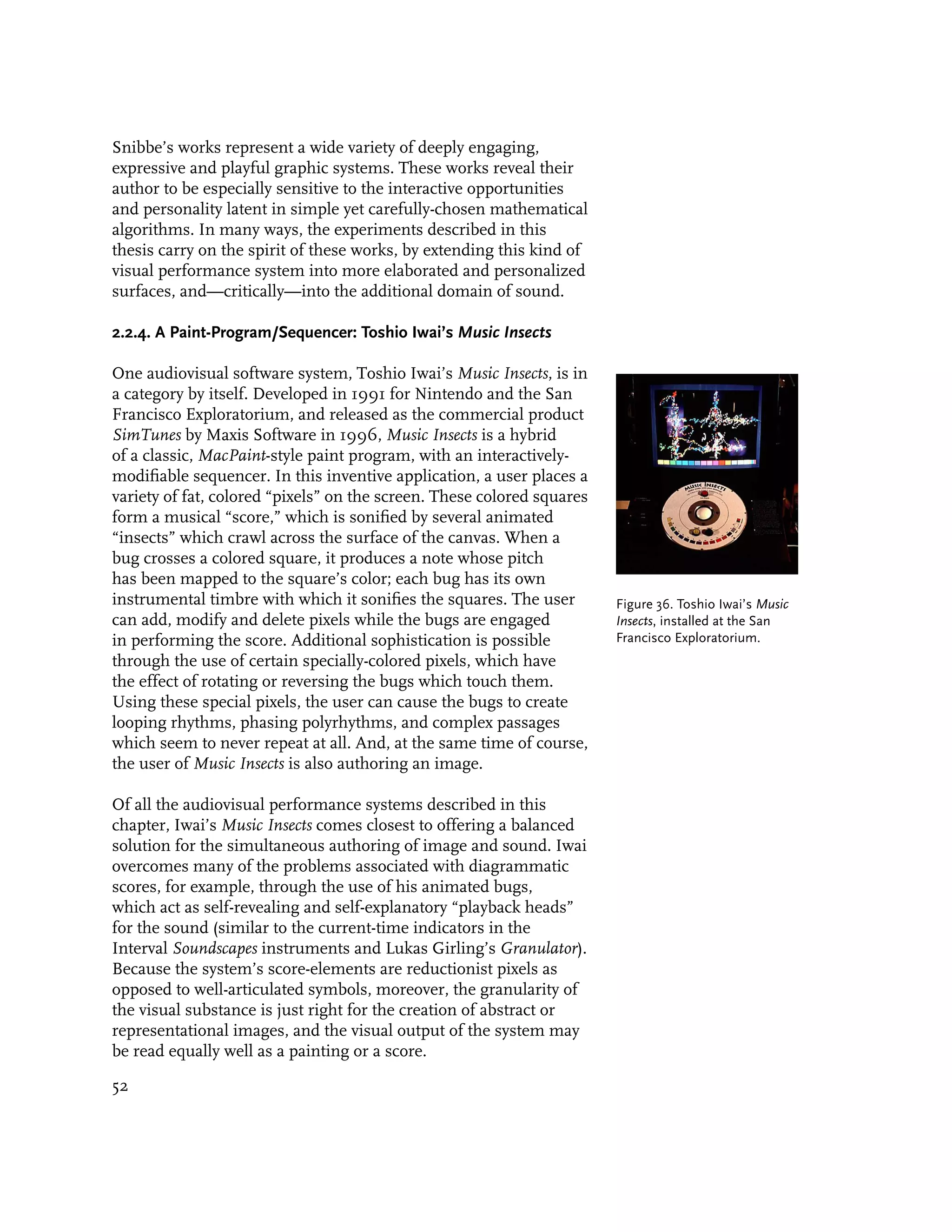
![Figure 33. A screenshot from
the Motion Phone in use
[Snibbe 1996].
The Motion Phone is a program which runs on a graphics
workstation. When first approached, the program presents palettes
of colors and shapes and a wide blank canvas. When a user draws
upon this canvas the speed and location of his marks are entered
into a digital animation loop. By pressing on the keyboard or on
the graphics tablet, the shape, size and color of the marks can be
simultaneously changed. As he continues to draw, his marks are
added into the same animation loop, allowing him to sequentially
layer multiple rhythms of form and color. [Snibbe 1996]
As with Maeda’s Timepaint, the Motion Phone produces animated
compositions from digitized recordings of gestures. Nevertheless,
there is an important difference between the two applications.
Whereas Maeda’s intent in Timepaint is to illustrate the implicit
temporality of gestural markmaking, Snibbe’s goal is to provide
a gestural tool for creating explicitly temporal compositions. Put
another way, Timepaint is a deconstructivist and Rationalist visu-
alization, while the Motion Phone presents a constructivist and
Romantic medium. It follows that the most important contribu-
tion of the Motion Phone is not that it enables animated construc-
tions to be created from captured gestures, but that it situates this
endeavor in the context of a full-featured tool for doing so.
Snibbe’s Dynamic Systems Series is a set of three applications
which explore further ways in which graphic systems can
computationally augment human movement. According to
Snibbe, “each work in the series is embodied as a dynamic
system—a model of natural, mathematical or algorithmic nature.
50](https://image.slidesharecdn.com/painterlyinterfacesforaudiovisualperformance-110920201619-phpapp01/75/Painterly-interfaces-for-audiovisual-performance-50-2048.jpg)
![Interacting with the system consists of reacting to and learning
the system. The pieces are meant to provide an immediate
sensation of touching an immaterial, but ‘natural’ world with
consistent and predictable reactions, but infinite variety” [Snibbe
1998]. One system in the series, the Bubbleharp, constructs
a Voronoi diagram from the user’s movements. This kind of
diagram is a common analysis tool in computer vision and
computational geometry, and has many analogies in nature, such
as the shape of bubbles or animal territories; it is defined as the
set of regions in the plane, given a set of site-points, such that
each region bounds the section of the plane which is closer to
its corresponding site-point than any other region. In Snibbe’s
system, the user deposits and records paths for animated site-
points in the plane, around each of which a “bubble” region
forms. The Bubbleharp system has the remarkable property that,
Figure 34. Stills from Scott owing to the nature of Voronoi diagrams, bubbles placed in
Snibbe’s Bubbleharp [Snibbe certain locations will crowd the plane, while other bubbles will
1998].
free up empty space.
The remaining two applications in Snibbe’s Dynamic Systems
Series explore other varieties of computational augmentation.
While the Bubbleharp augments gestures with a geometric
construction, Snibbe’s Lazy Line augments human movement
with a generalized kernel-based filter, and his Gravilux,
like Haeberli’s DynaDraw, augments gesture with a physical
simulation. In Lazy Line, the user may apply one of several simple
digital filters to a line as it is drawn; if the filter is a lowpass
filter, for example, the line is smoothed, while a highpass filter
exaggerates wiggles. Of Lazy Line, Snibbe writes: “By passing a
3-element kernel filter over a line while you are drawing it, it is
possible to add character to the line, while admittedly distorting
the artist’s form. The purpose of the tool is the process of
interacting with this filter, rather than the final drawing” [Snibbe
Figure 35. Scott Snibbe’s 1998].
Gravilux [Snibbe 1998].
Snibbe’s Gravilux places the user’s cursor into a simplified
physical simulation of gravity. In this system, the user applies
gravity-like forces to a dense field of points; attracted to the cursor
by a classic inverse-square force formula, the points can be teased
and torqued in various ways, “slingshotting” the cursor when they
pass too closely. In this way, the user is able to learn a little about
what it might be like to “paint with stars” [Snibbe 1998].
51](https://image.slidesharecdn.com/painterlyinterfacesforaudiovisualperformance-110920201619-phpapp01/75/Painterly-interfaces-for-audiovisual-performance-51-2048.jpg)
![3. Design Experiments
In support of this thesis research, I have developed a series
of experimental software applications which explore the design
space of computational instruments for visual and audiovisual
performance. This chapter details these projects, beginning
with a group of four pertinent silent experiments (Streamer,
Escargogolator, Polygona Nervosa, and Directrix) I conducted prior
to my Fall 1998 matriculation in Professor John Maeda’s
Aesthetics and Computation Group. After these I discuss a set of
five new instruments developed over the past two years, which
represents the present culmination of my research into the
design of systems for the simultaneous performance of dynamic
graphics and sound: Yellowtail, Loom, Warbo, Aurora and Floo.
The present chapter devotes a short section to each of the
nine experimental systems; each of these sections treats a
given system’s mechanism, its particular strengths or novel
contributions, and its shortcomings and limitations.
3.1. Preliminary Silent Experiments, 1997-1998
This section describes the design of four silent environments—
Streamer, Escargogolator, Polygona Nervosa, and Directrix—which
I developed during 1997 and 1998 at Interval Research
Corporation. The first three of these were created in a
collaboration with Scott Snibbe, who was a colleague of mine at
Interval at the time, and who had developed the Motion Phone
animation environment (see Chapter Two) between 1991 and
1995. Although these four works predate my matriculation
at MIT, I include them in this chapter for the reason that
their design narratives, taken together, introduce many of the
aesthetic goals, design guidelines, and technical issues which have
structured the development of my newer sonified works. Apart
from brief descriptions of Streamer and Escargogolator in [Snibbe
and Levin 2000], none of these works have received any detailed
treatment or explication in print.
Streamer, Escargogolator, Polygona Nervosa and Directrix are proto-
types of “visual instruments”—quickly-executed experiments into
the plausible analogy, in the visual domain, of musical instru-
ments. Instead of allowing the creation of sound over time, these
systems permit a performer to produce dynamic imagery over
59](https://image.slidesharecdn.com/painterlyinterfacesforaudiovisualperformance-110920201619-phpapp01/75/Painterly-interfaces-for-audiovisual-performance-59-2048.jpg)
![time. As with conventional musical instruments, these systems
were designed to offer their users the possibility of an invested,
highly-present expressive engagement—a state which psycholo-
gist Mihaly Cziksentmihalyi has termed “creative flow”—with the
medium of dynamic abstraction [Cziksentmihalyi 1996]. Each
system attempts to do this by presenting an environment which:
• uses human gesture as a raw input of rich complexity;
• creates an animated, living environment, established by
continuously changing synthetic graphics;
• has a quickly apprehensible interface that affords
immediately satisfying results; yet at the same time,
provides for a wide range of possible expression that one
can continue to master over time; and
• can elicit joy, surprise and delight solely with abstract
graphics [Snibbe and Levin 2000].
Several factors contributed to the genesis of these four silent
works. One important influence was the set of advanced visual
languages developed by Oskar Fischinger, Norman McLaren and
other abstract animators in the early- and mid-20th century. The
transposition of these dramatic and personal languages from the
realm of composition (in film) to the realm of performance (in
color organs) had been largely restricted by the limitations of
the physical world. Computer graphics’ apparent capacity to void
the laws of physics, however, held the promise of making this
translation possible.
A second factor was an aesthetic opportunity made possible by a
technological development: when full-screen animation became a
reality for desktop computers in the mid-1990s, most developers
of interactive graphics overlooked the expressive potential of two-
dimensional compositions, in favor of the “realism” promised by
3D, texture-mapped virtual realities. We sensed that the domain
of two-dimensional imagery, so highly developed in the plastic
arts of painting and cinema, had only begun to benefit from the
affordances of real-time interaction and computation.
The most significant factor in the development of the four silent
works, however, was undoubtedly the combined influence of
Scott Snibbe’s Motion Phone, Paul Haeberli’s DynaDraw and John
Maeda’s TimePaint. Taken together, these systems all pointed
toward the idea of an inexhaustible, exceptionally malleable,
animated visual substance. This idea was a welcome contrast to
60](https://image.slidesharecdn.com/painterlyinterfacesforaudiovisualperformance-110920201619-phpapp01/75/Painterly-interfaces-for-audiovisual-performance-60-2048.jpg)
![the considerable limitations of the sprite-based and ROM-based
systems, such as Director and mTropolis, which dominated the
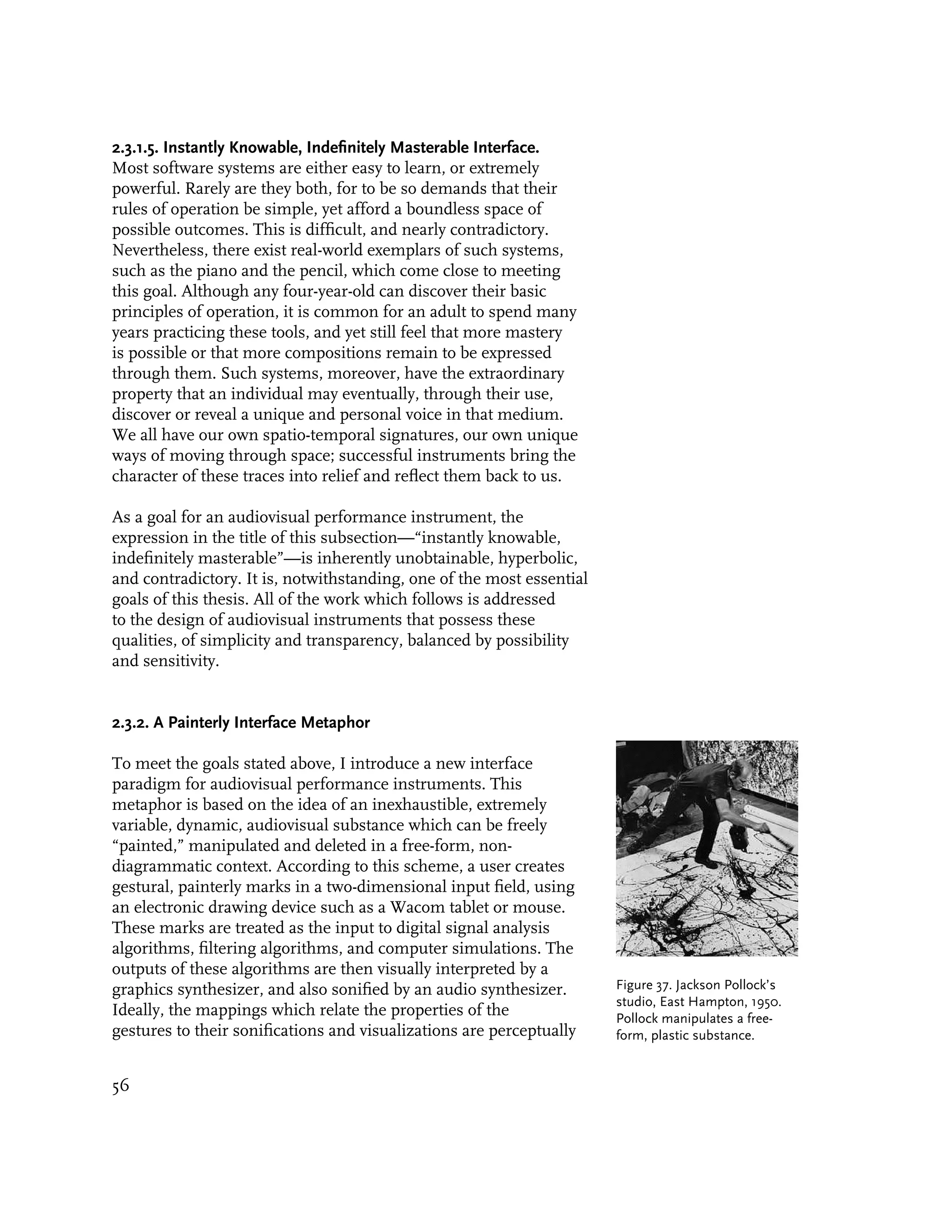
field of consumer animation authoring environments during
the 1990’s. Having directly experienced these limitations during
the development of my Rouen Revisited installation [Levin and
Debevec, 1996] and several other Interval projects, I was eager
to explore the woolly frontier of dynamic computational form to
which Motion Phone, DynaDraw and TimePaint pointed.
At the same time that Motion Phone, DynaDraw and TimePaint
indicated a broad and fertile territory of interactive graphics,
these systems were also constrained by an interesting array of
limitations. Motion Phone, for example, restricted all animations
to looping compositions of circles, squares and triangles. Both
DynaDraw and Motion Phone made heavy use of visually
extraneous GUI elements, such as sliders, clearly suggesting
that more research would be necessary before all aspects of an
dynamic image could be performed with the same degree of
direct physical control as a traditional static image. TimePaint was
a provocative visualization of the nature of animated form, and
embodied a suggestively different temporal model from either
Motion Phone or DynaDraw, but it also had an extremely limited
graphical repertoire. In the development of Streamer and the
other silent works described in this section, these limitations were
treated as opportunities to explore and invent an expanded design
vocabulary for animation performance systems. Thus I set about
to investigate how such systems might embody other temporal
models, other graphical models, and other models and modes of
interaction.
3.1.1. Streamer
By December of 1996 I had spent many hours using and enjoying
Scott Snibbe’s Motion Phone, and had developed a strong desire to
create a response to the many interesting ideas embodied within
it. I identified two areas in which I felt there were immediate
opportunities for such a response. I first noted that Motion Phone
restricted its user to a very limited palette of Platonic forms—
namely circles, squares, triangles and rectangles—and I therefore
sought to develop a means by which a wider range of more
malleable visual forms could be expressed. I also noted that
Motion Phone’s animations were exclusively constructed around
the exact reproduction of recorded human gesture. I sought
61](https://image.slidesharecdn.com/painterlyinterfacesforaudiovisualperformance-110920201619-phpapp01/75/Painterly-interfaces-for-audiovisual-performance-61-2048.jpg)
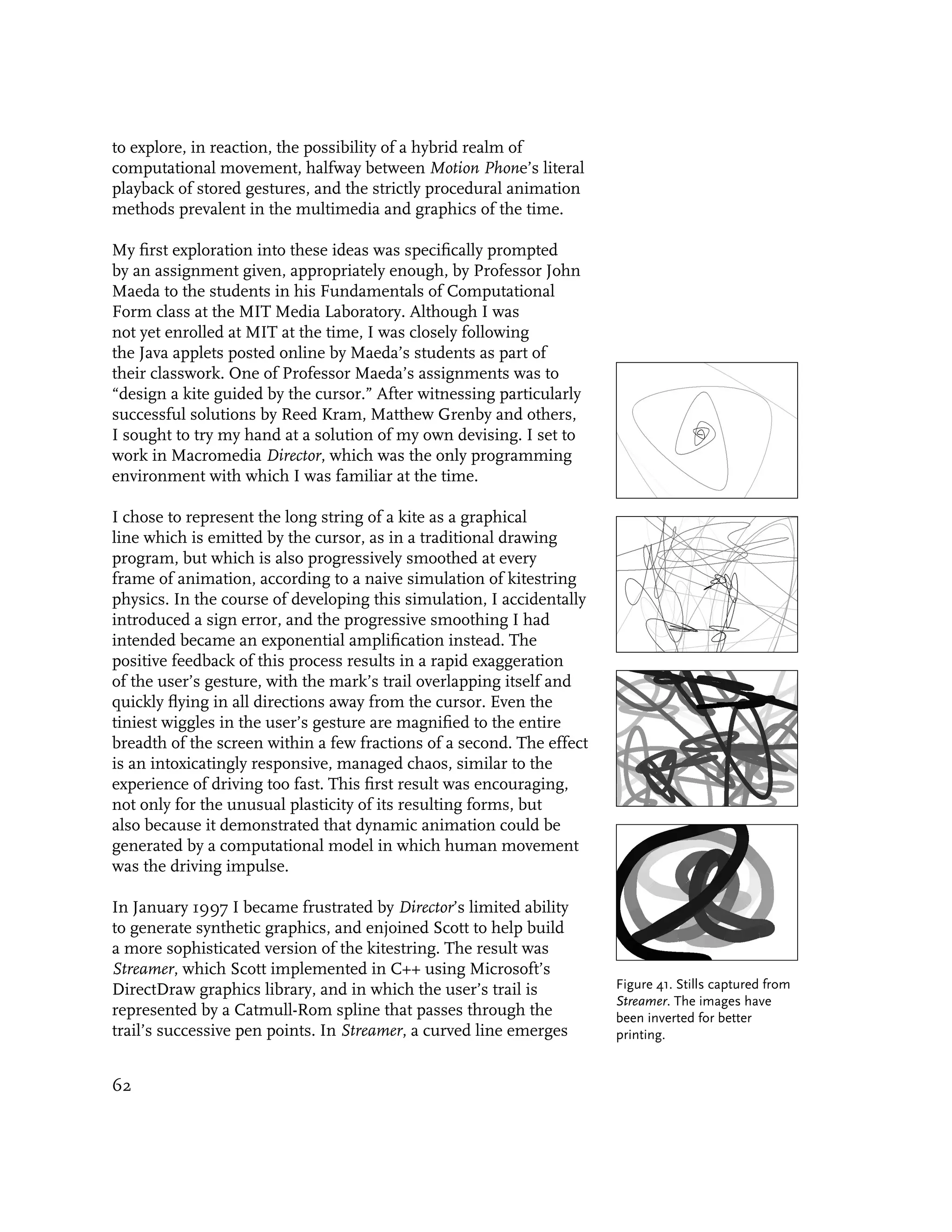
![from the movement of the pen as long as the button is down.
Although the behavior of this curved line is exaggerated in a
manner that calls to mind the expanding smoke from a cigarette,
or ripples in water, there is no computational randomness added
to the system—the mechanical noise in the user’s joints is
sufficient to produce an interesting and organic result. As soon
as the user releases the button, the curved line dissolves into
blackness.
Figure 42. An image captured
from Streamer in use. The
image has been inverted for
better reproduction in the
printed medium; ordinarily,
Streamer appears as a bright
white line that recedes into a
pitch black background.
Sometime later, Bill Verplank at Interval introduced us to
Paul Klee’s Pedagogical Sketchbook, in which Klee undertook a
systematic treatment of the formal elements of visual abstraction
[Klee 1923]. We found a natural affinity between our Streamer
software and Klee’s instructional drawings, which provocatively
suggested how a line might be brought to life. Among Klee’s
first words in this book are, “A line is a walk for walk’s sake.”
As Scott and I embarked on a set of collaborative explorations
of the line’s potential for dynamic expression, we took a cue
from Klee and strove to design systems which emphasized their
process of creation, over their products [Snibbe and Levin 2000].
Escargogolator, our next collaboration, extended this theme.
63](https://image.slidesharecdn.com/painterlyinterfacesforaudiovisualperformance-110920201619-phpapp01/75/Painterly-interfaces-for-audiovisual-performance-63-2048.jpg)
![Figure 43. The first two pages
from Chapter One of Paul
Klee’s Pedagogical Sketchbook
(1923), in which he undertakes
a systematic study of the
formal elements of visual
abstraction. Klee begins with a
study of the Line [Klee 1923].
3.1.2. Escargogolator
In February 1997, Scott Snibbe and I collaborated on the design
of Escargogolator, an abstract animation instrument in which a
user’s gestures are smoothly exaggerated or diminished according
to their local curvatures.
As with Streamer, the dynamic animation in Escargogolator is
generated by a computational model in which human movement
acts as the driving impulse. Unlike Streamer, which only produces
reactive graphics in response to the user’s real-time input,
Escargogolator obeys a different temporal and interaction model
in which a progressive transformation is applied to a user’s
mark during and after its creation. Thus, while Streamer’s display
evaporates almost instantaneously when its user ceases to feed
energy into its system, Escargogolator allows a user to establish a
configuration of gestural “initial conditions,” and then observe the
manner in which these conditions evolve or devolve over time.
The specific transformation applied to the user’s marks in
Escargogolator was inspired by the mathematical construction
called the evolute, which I had read about in Eugene Shikin’s
splendid Handbook and Atlas of Curves [Shikin 1995]. In classical
geometry, the evolute of a given curve is created by computing,
for each position on the curve of interest, its center of curvature
at that position. These centers of curvature, connected and taken
together, form that particular curve’s evolute. (Reciprocally, the
original curve of interest is said to be the evolvent of its evolute
curve.) The range of possible curves of evolution is essentially
64](https://image.slidesharecdn.com/painterlyinterfacesforaudiovisualperformance-110920201619-phpapp01/75/Painterly-interfaces-for-audiovisual-performance-64-2048.jpg)
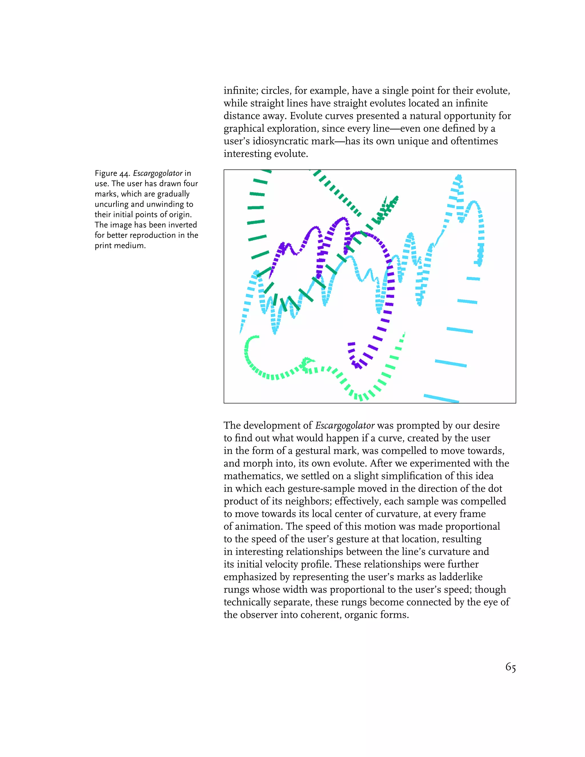
![The behavior which emerges from this system is peculiarly
wormlike and has several interesting properties. Its most notable
characteristic is that all of Escargogolator’s strokes gradually and
inexorably unwind to their points of origin—that is, strokes
eventually straighten themselves and ultimately shrink down to
their first, single point (due, in part, to the system’s boundary
conditions). It is an interesting exercise, for example, to write in
cursive and watch the letters evolve into a meaningless scribble
[Snibbe and Levin 2000]. The precise manner in which the
strokes uncurl themselves, though wholly deterministic, has the
additional property that it is handed. Thus the dynamisms of
the system are not only based on the amount of curvature, but
also on the curvature’s sign: clockwise portions of the curve
gradually expand over time, while counterclockwise portions of
the curve collapse. As a result, marks with certain configurations
of curvature may grow substantially in size before ultimately
shrinking down.
Escargogolator’s chief contribution is the presentation of an
alternative temporal model for interactive performance—one in
which the user creates a set of initial conditions, and can then
witness how those conditions evolve and disintegrate over time.
Unlike Snibbe’s Motion Phone and several of the experimental
systems described in this thesis (including Polygona Nervosa, Figure 45. Additional images
discussed next), the conditions established by the user in captured from Escargogolator in
Escargogolator do not create a perpetually looping rhythm. If use.
Streamer could be said to resemble a flute (insofar as there is
only activity on the screen so long as the user infuses the system
with energy), then Escargogolator is like a large gong, whose sound
slowly fades away with an interesting timbral evolution.
3.1.3. Polygona Nervosa
In March 1997, I turned my attention from lines to shapes, and
conceived of an interaction by which a user could simultaneously
specify both the form and also the quality of movement of
an animated polygon. I again developed a prototype of this
interaction in Director, but the limitations of the Macromedia
graphics environment prohibited the display of filled polygons
or rounded forms. Shortly afterwards Scott ported the algorithm
to his DirectDraw-based graphics environment, and these
limitations were obviated. We named the new instrument
Polygona Nervosa after its shapes’ lively condition.
66](https://image.slidesharecdn.com/painterlyinterfacesforaudiovisualperformance-110920201619-phpapp01/75/Painterly-interfaces-for-audiovisual-performance-66-2048.jpg)
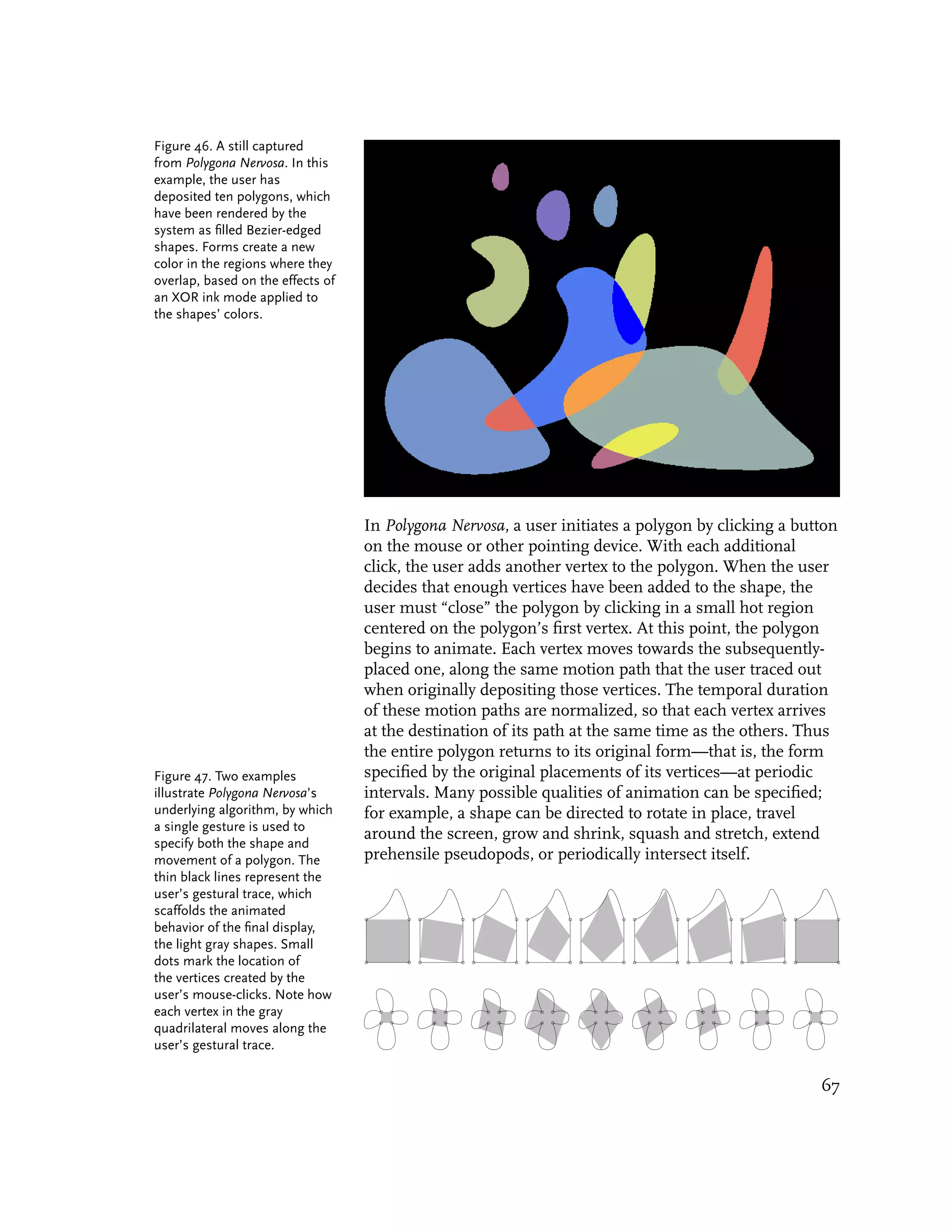
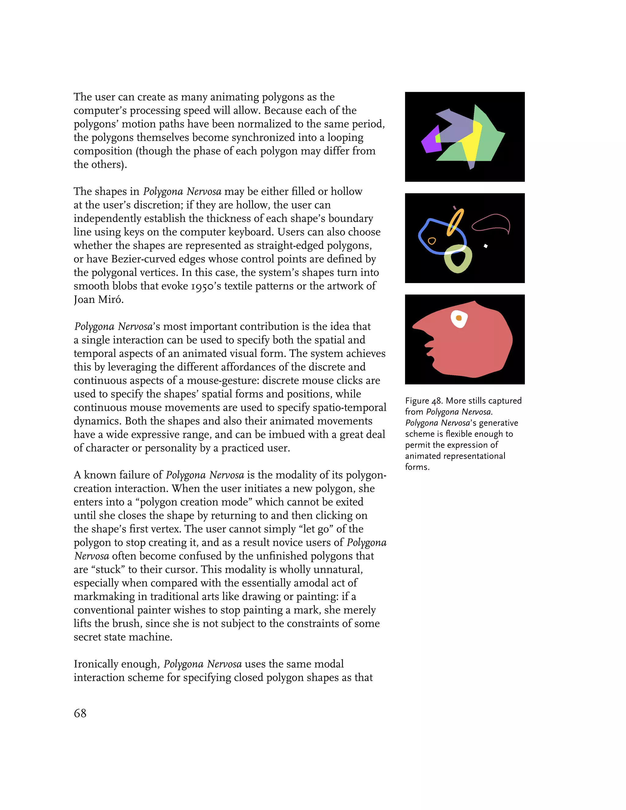
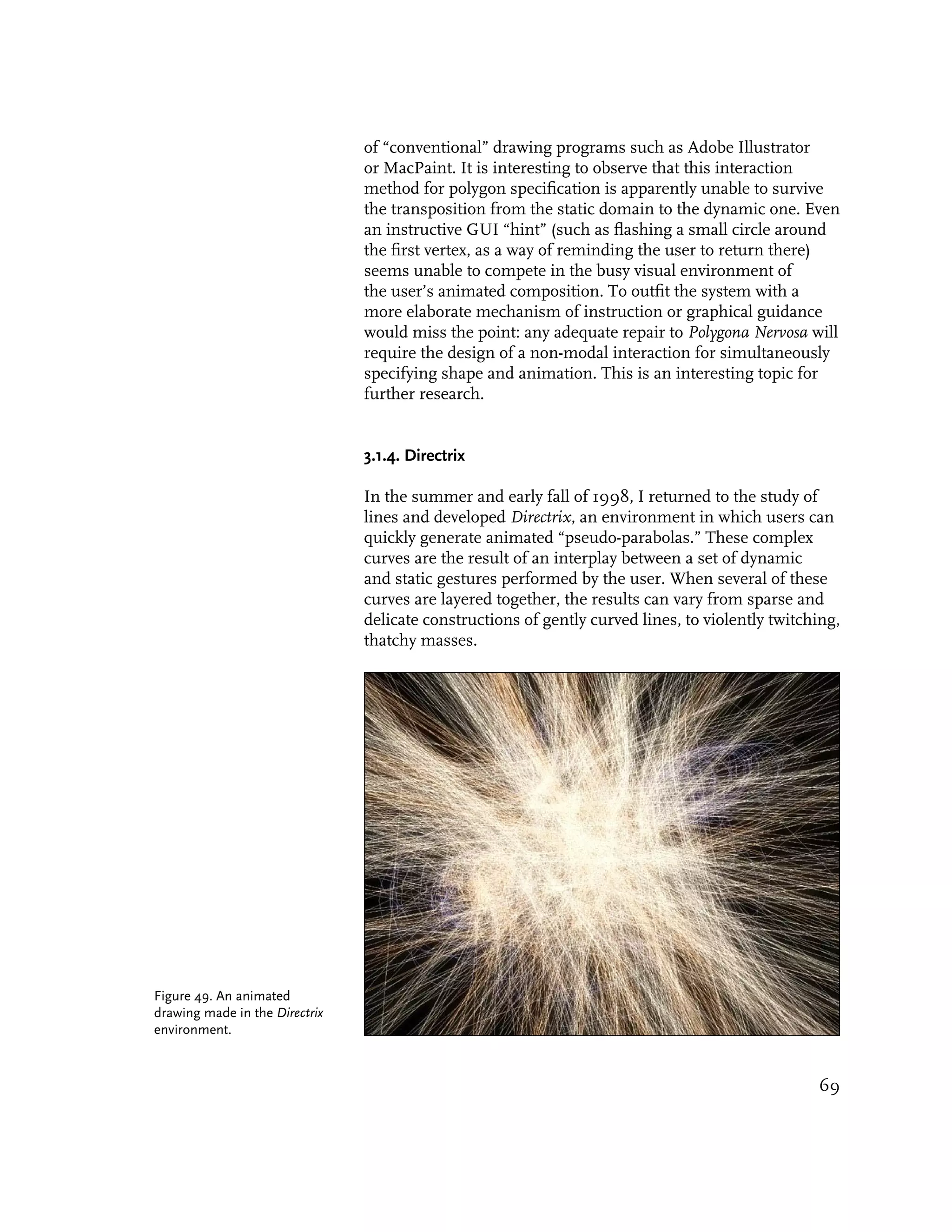
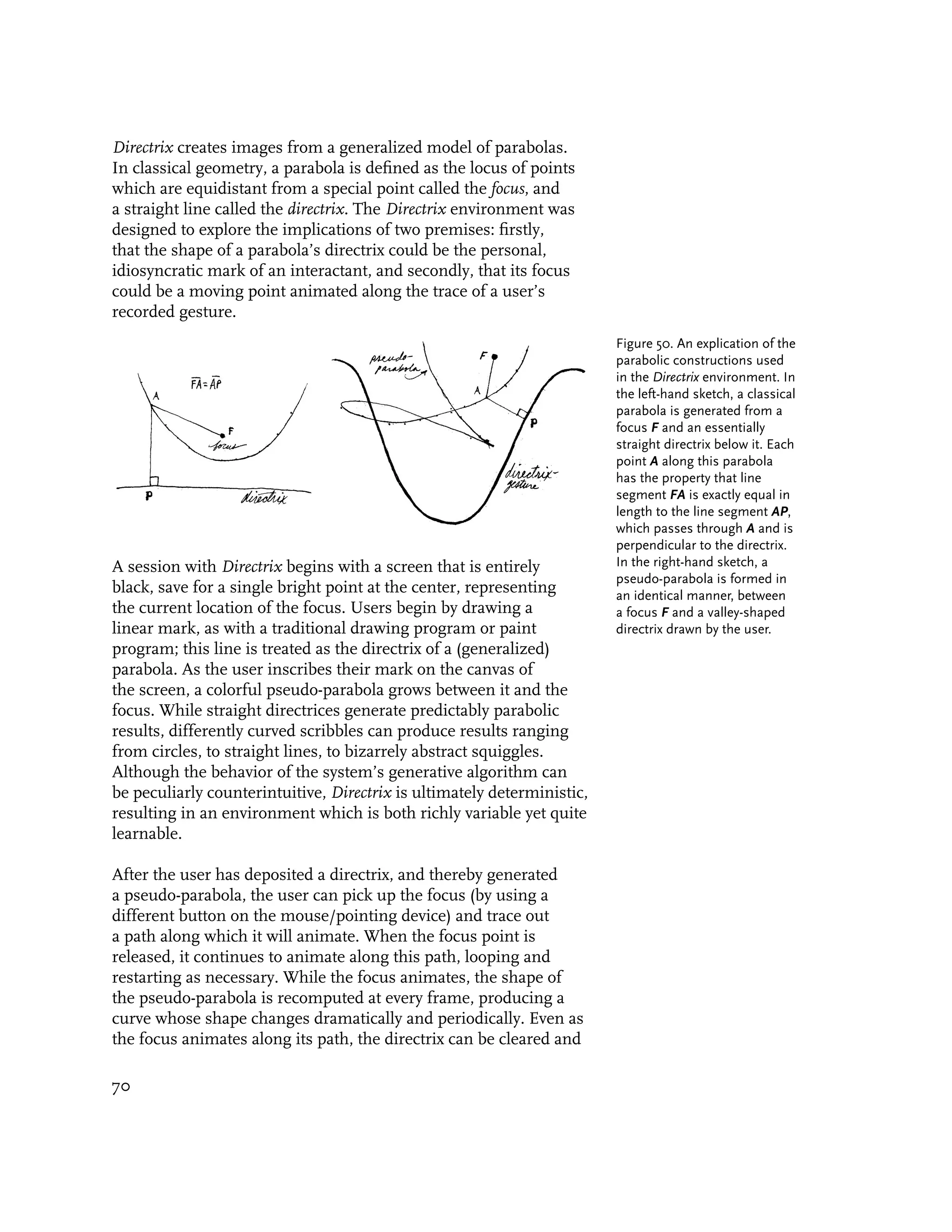
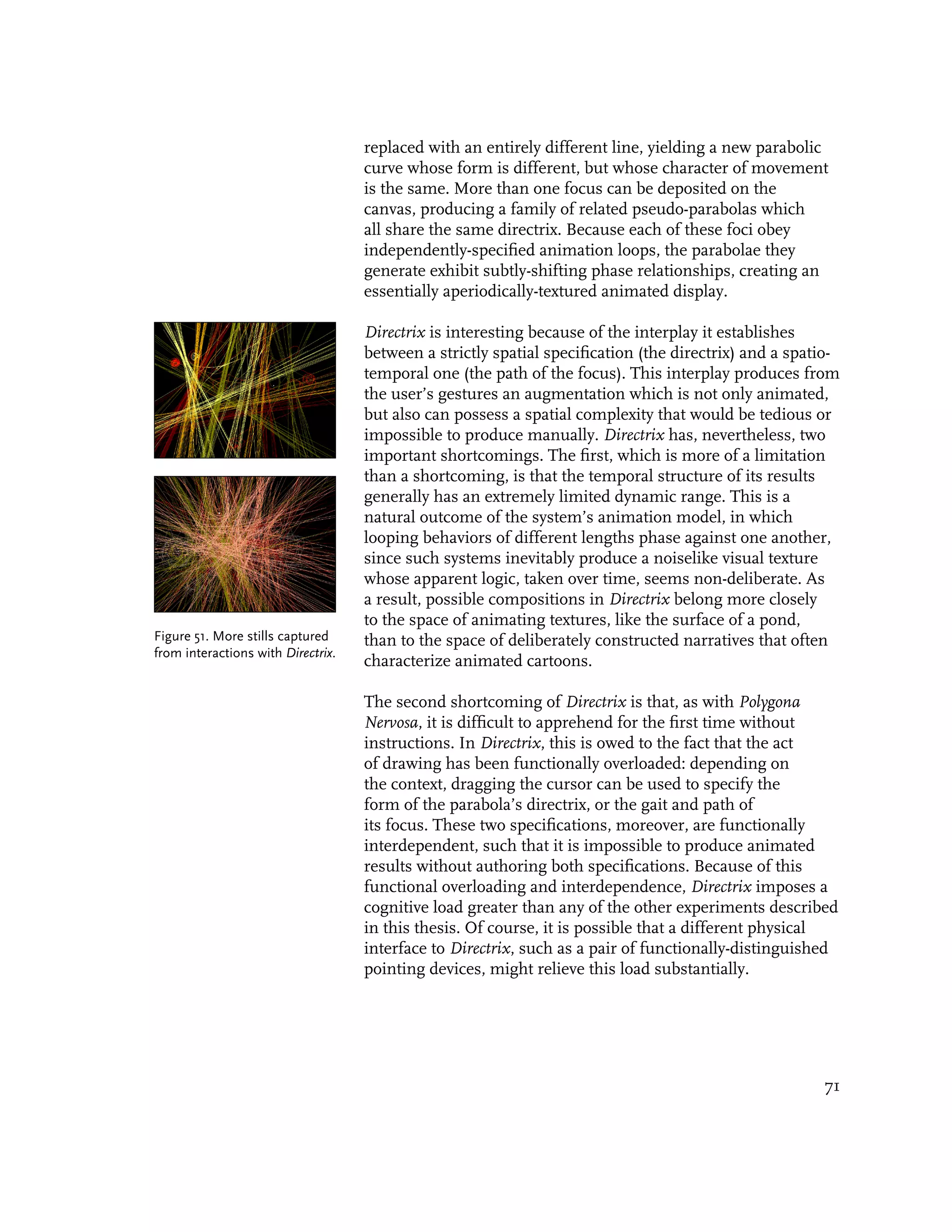
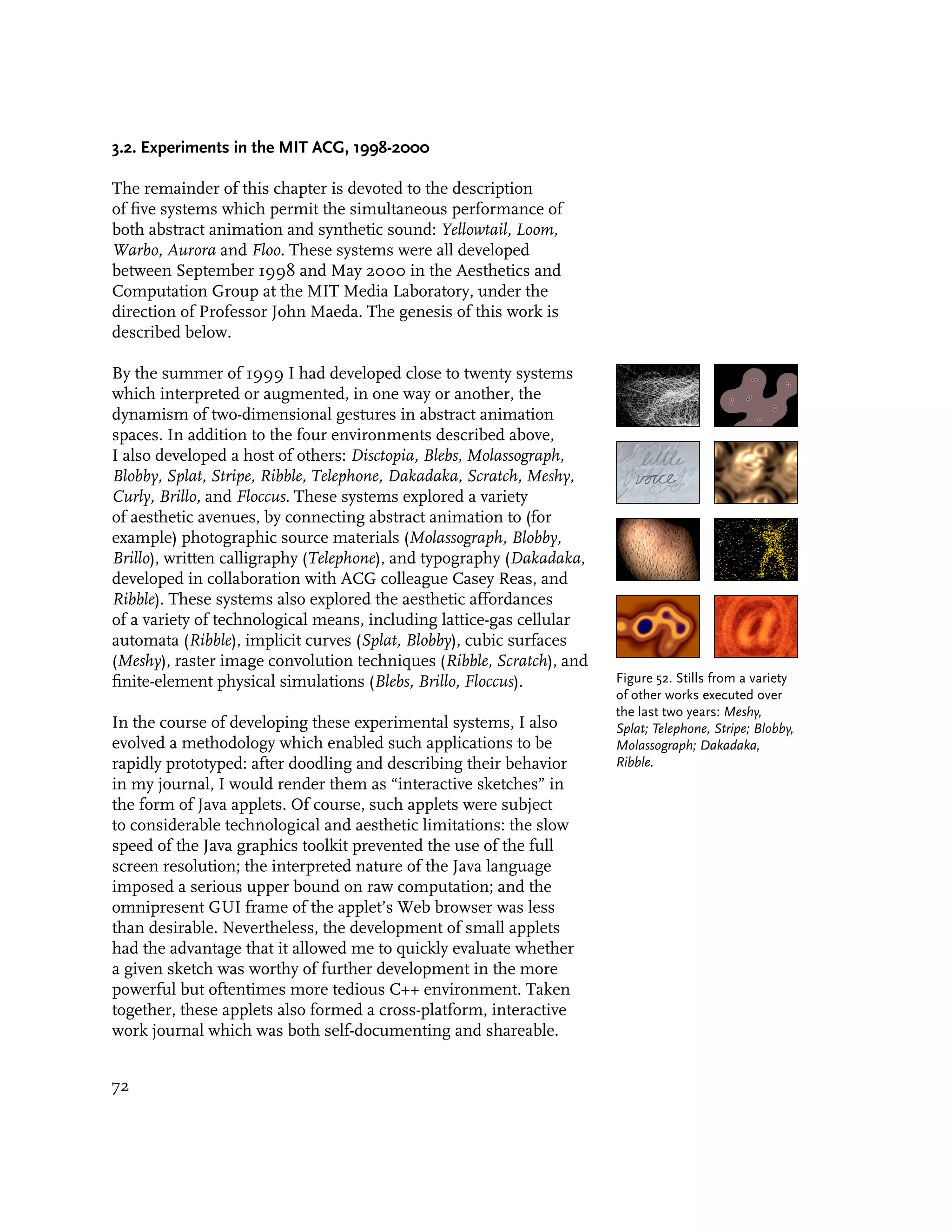
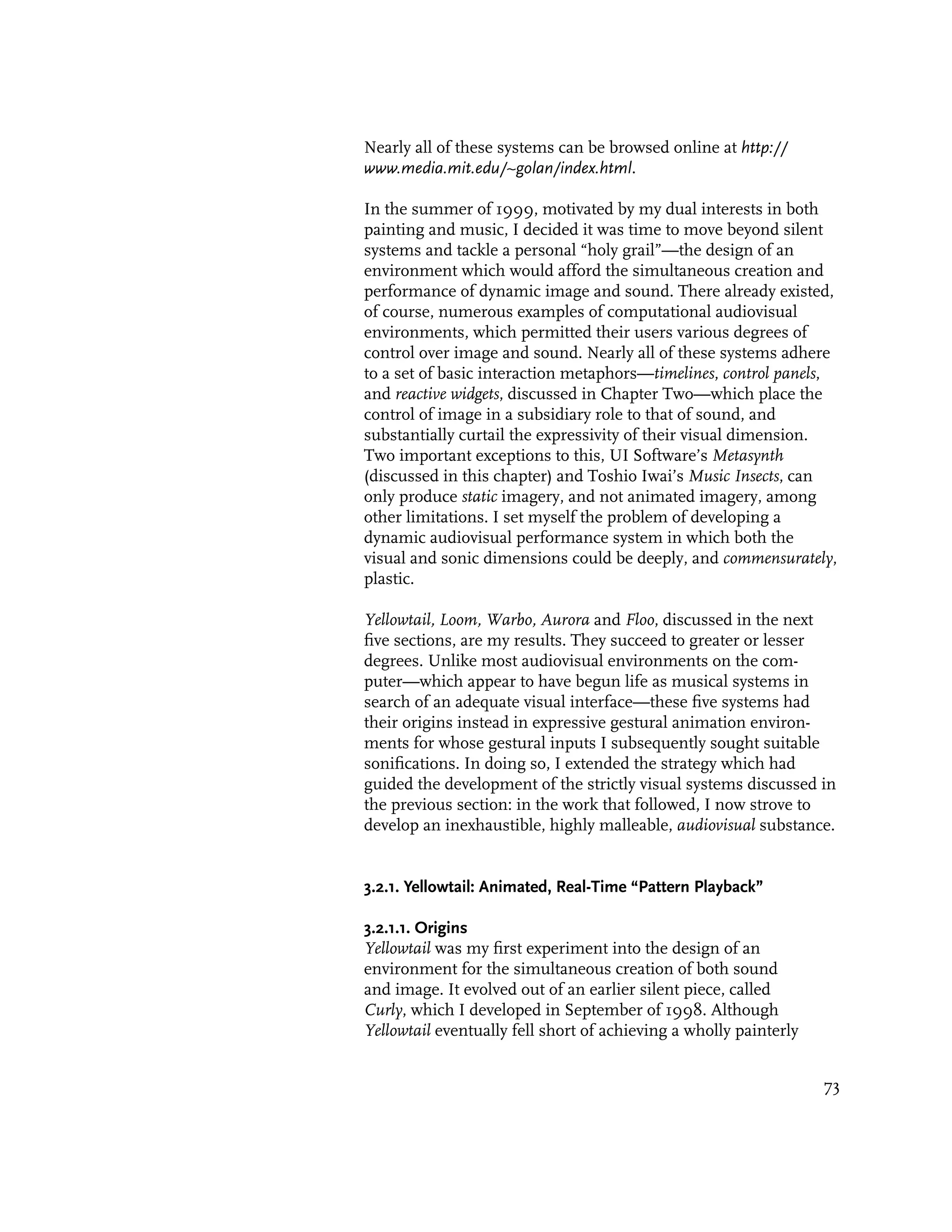
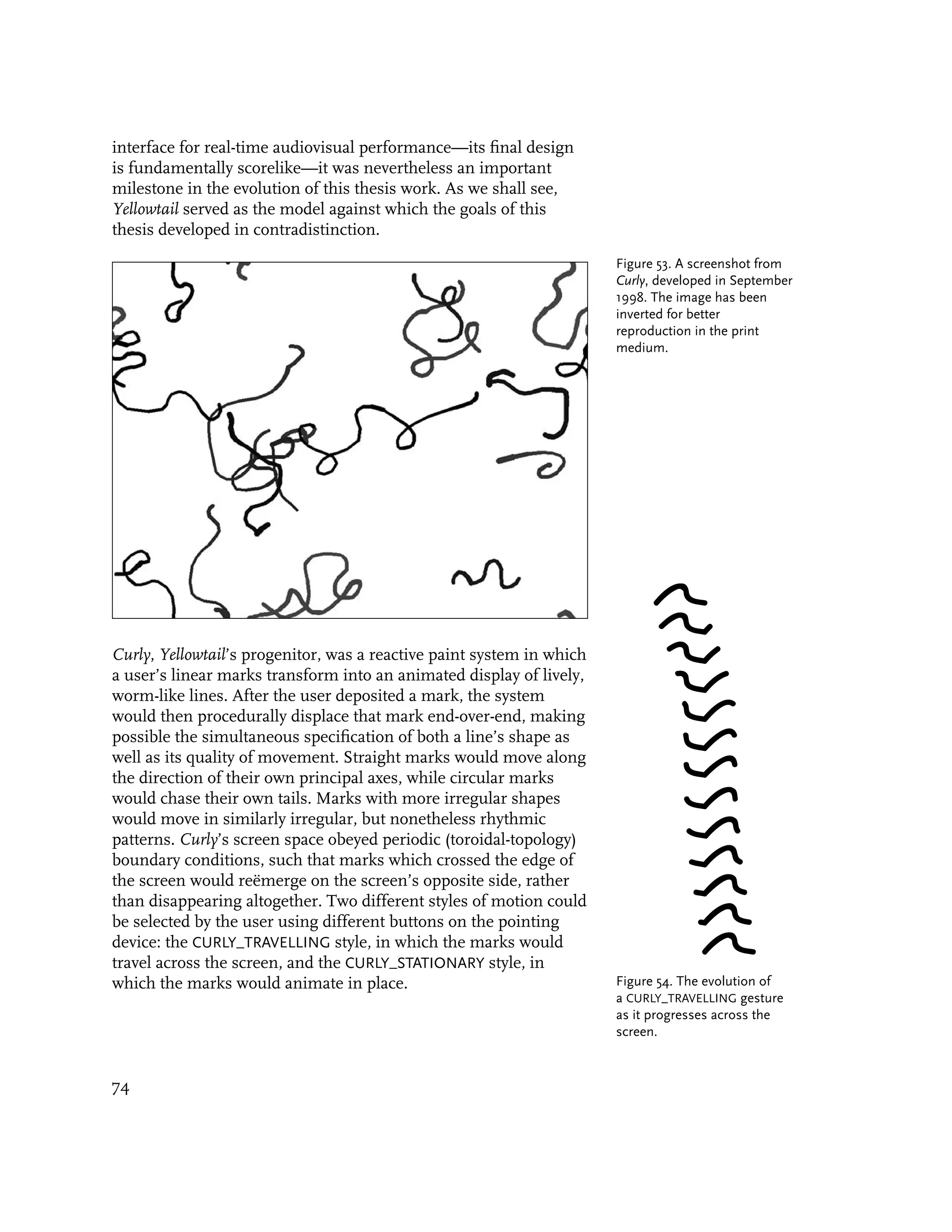
![Figure 55. The marks in Curly
can obey one of two different
styles of animation. On the
left is the CURLY_TRAVELLING
style, in which a mark
propagates along an axis of
movement defined by its
endpoints. On the right is
the CURLY_STATIONARY style, in No randomness was employed in the procedural animation of the
which a mark animates in place “curlies.” Instead, their animated behavior is strictly determined
by cycling its shape through by the shape and speed of the mark when it was drawn.
the stationary positions initially Nevertheless, because each line repeats according to its own
established by its original
endpoints.
natural period, the complex phase relationships of the different
marks produce the effect of an ever-changing yet coherent
animated texture.
3.2.1.2. Sonification
In June of 1999, I had the idea of sonifying Curly by treating
its animating canvas as an “inverse spectrogram.” Ordinarily,
a spectrogram is a diagrammatic image used to visualize the
frequency content of sound data. In a typical spectrogram, Short-
Time Fourier Transforms (STFT) are applied to extremely small
portions of a waveform, and represent the time-based information
of the wave segment as components in the frequency domain.
Transforms from adjacent windows of sound data are then
rendered as a picture to create an image of the sound’s frequency
content versus time.
Spectrograms were originally developed to analyze sounds, such
as speech, but took on provocative new possibilities when used in
reverse, as a means of synthesizing sound. This technique, called
pattern playback, was first developed by the speech researcher
Frank Cooper in the early 1950’s [Cooper 1953]. Cooper showed
that it was possible to draw a pattern of paint splotches on plastic,
and then use a machine of his own design to play back the sound.
This made it possible for his lab to do many psychoacoustic
experiments, and it also helped validate the use of a spectrogram
as an analysis tool [Slaney 1995]. Cooper’s machine used an array
of light sources, each modulated at one of the fifty harmonics of
120Hz, to illuminate a strip of acetate tape. Patterns were painted
on the film, and the light that was reflected from the pattern
was transformed by photoresistors into a varying voltage and then
amplified for auditory playback. The result, according to Cooper,
was “highly intelligible” speech [Slaney 1995].
75](https://image.slidesharecdn.com/painterlyinterfacesforaudiovisualperformance-110920201619-phpapp01/75/Painterly-interfaces-for-audiovisual-performance-75-2048.jpg)
![Since then, a number of researchers and companies have
developed spectrogram-based drawing systems for the analysis
and resynthesis of sound. In these systems, a digital image
representing the intensity of different audio frequencies over time
is used as a “score” for an additive or inverse-FFT synthesizer
(a sound synthesizer in which a large number of weighted
sinusoids are summed to produce complex tones). Examples
of such systems include John Strawn’s eMerge (1985), Gerhard Figure 56. “Pattern Playback”
of hand-painted spectrograms
Eckel’s SpecDraw (1990), B. Holloway’s LemurEdit (1993), and made by Frank Cooper in the
Malcolm Slaney’s Pattern Playback Plugins (1995), the last of early 1950’s: (a) the original
which embedded sound spectrogram technologies in an Adobe spectrogram pattern, (b)
Photoshop plugin [Roads 1993, Slaney 1995]. Perhaps the most spectrogram of the inverted
signal, (c) original spectrogram
popular spectrogram resynthesizer, however, is UI Software’s
with pitch harmonics, (d)
Metasynth for the Macintosh [UI Software 1998], which merges spectrogram of inverted signal
an additive sound synthesis engine with a variety of spectrogram- with pitch harmonics [Slaney
specific image editing tools and filters. 1995].
Figure 57. An interface from
UI Software’s Metasynth, a
spectrogram-based synthesizer
[UI Software 1998].
As powerful as such systems are, I felt that they could be
improved or extended in two important ways. Firstly, none of
the pattern playback systems were designed with the capacity to
support real-time performance. In all cases, including Metasynth,
the metaphor of interaction has been modeled after that of a
traditional music sequencer: users paint into the spectrogram,
click on the tapedeck-style “play” button, evaluate the sonic
results, stop the playback, and then paint some more. This slow
feedback loop of painting and audition is suitable for a meticulous
style of composition, but makes improvisatory performance
difficult or impossible. In sonifying Curly with pattern playback
technology, I sought to collapse the duration of this feedback
loop in order to produce an effective simultaneity of creation
76](https://image.slidesharecdn.com/painterlyinterfacesforaudiovisualperformance-110920201619-phpapp01/75/Painterly-interfaces-for-audiovisual-performance-76-2048.jpg)
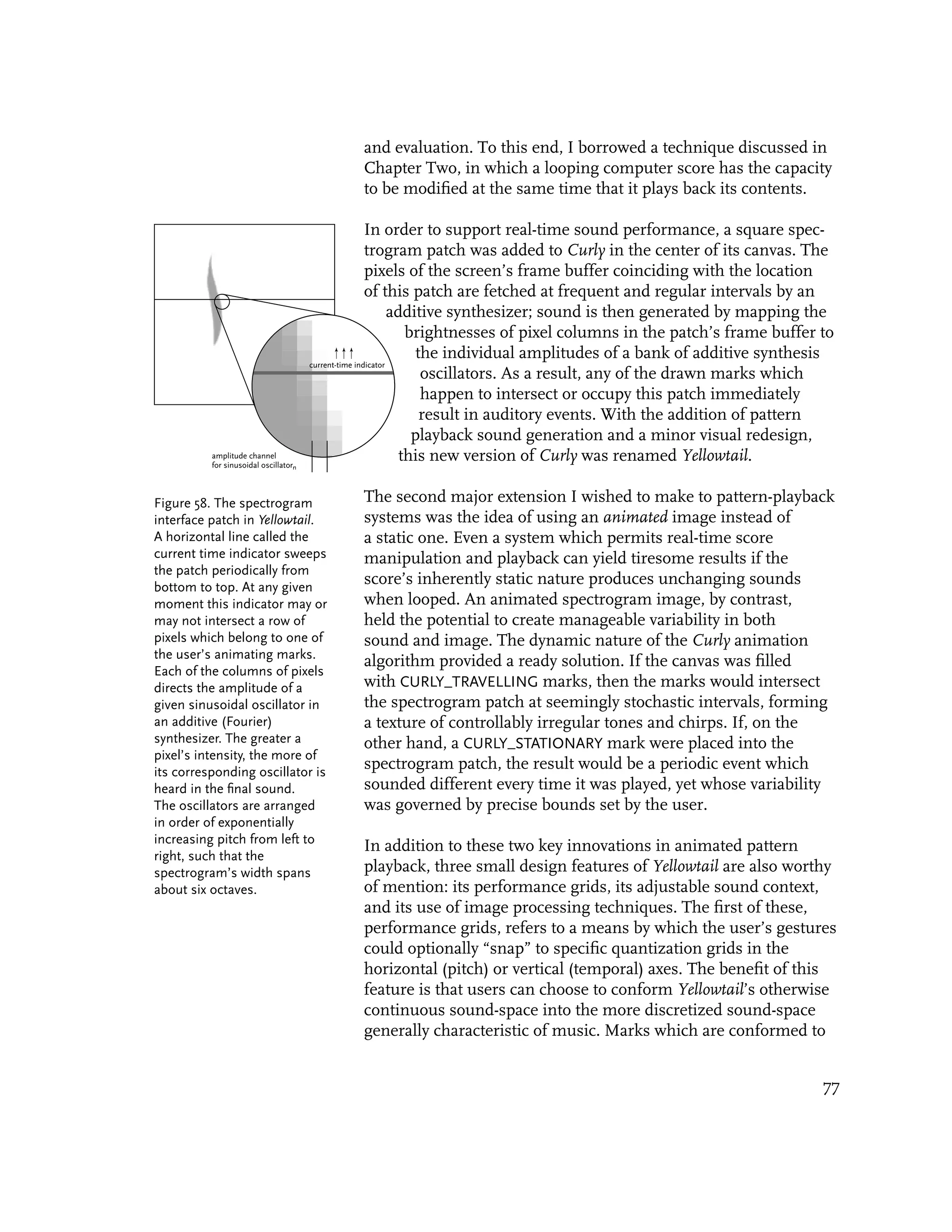
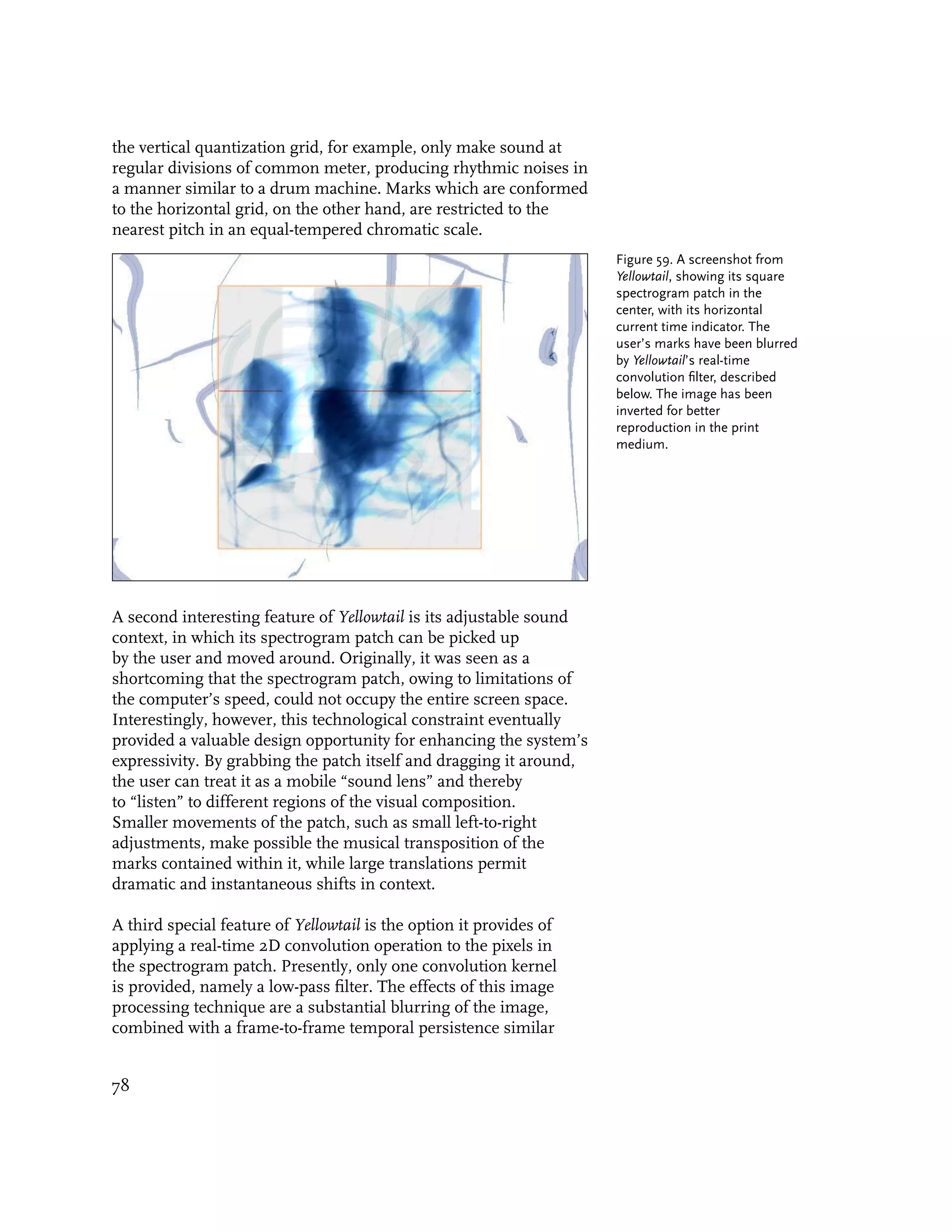
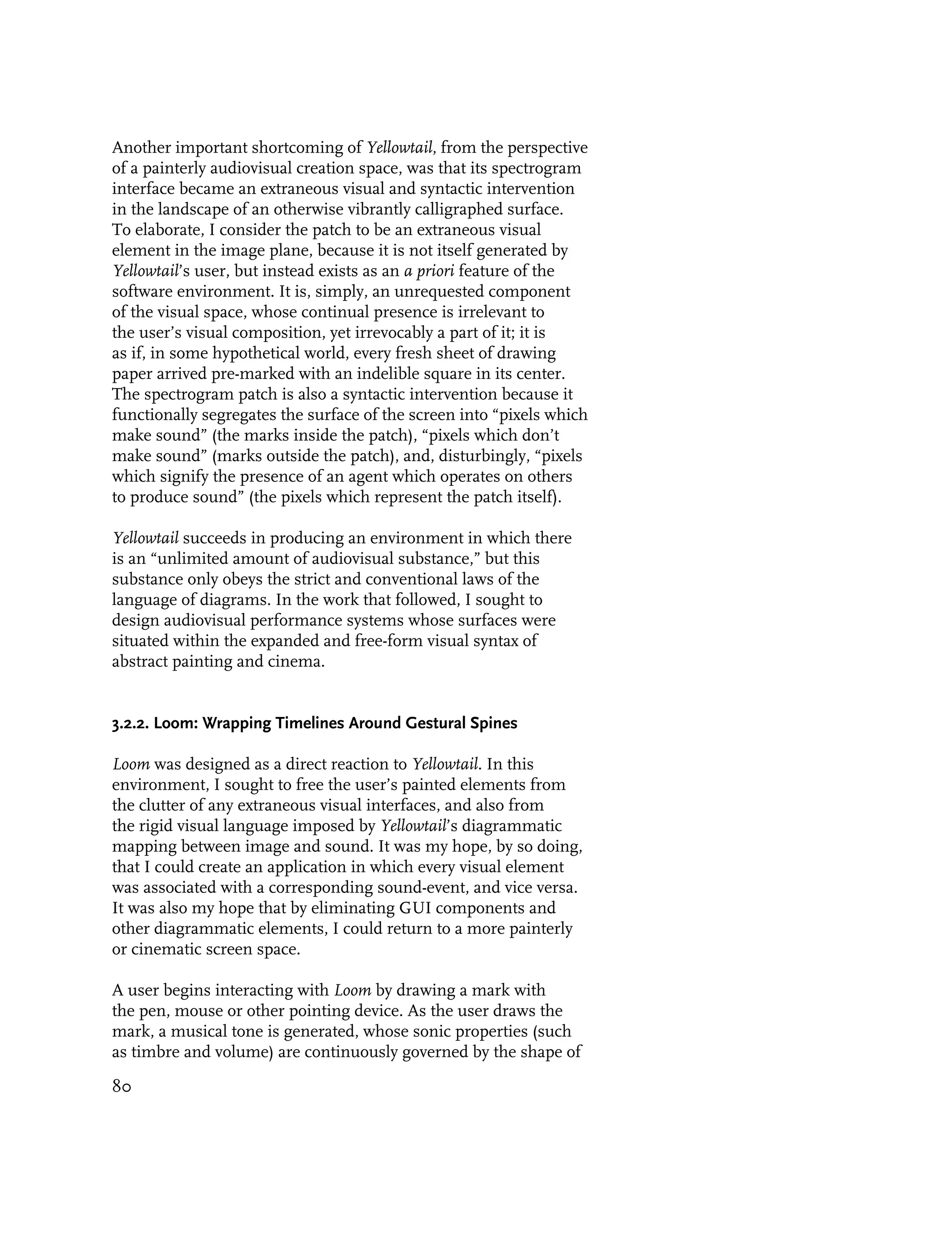
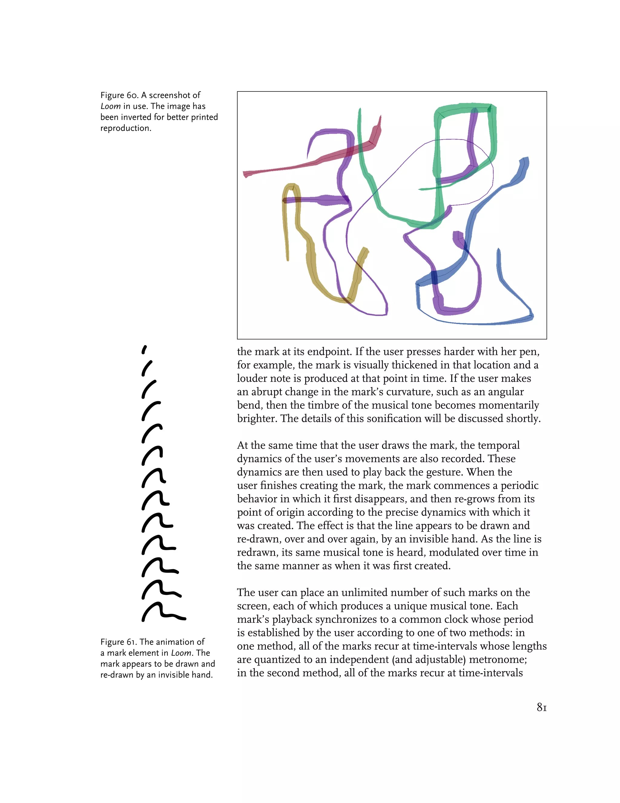
![whose lengths are integral multiples of the first mark that the Figure 62. The user’s gestures
user deposited. Even though it is possible (in either method) for recur periodically in Loom. All
of the marks have periods
all of the visible marks to have periods of the same duration, which are an integral multiple
their phases may differ considerably according to how they were of some base length. In the
temporally placed by the user. As a result it is possible to perform example shown here, the lower
marks which yield interesting rhythmic textures, interlocking two marks have the same
period, while the uppermost
polyrhythms, and call-and-response patterns.
mark has a period exactly
twice as long (that is, it
recurs exactly half as often).
Although the marks recur in
lock-step with each other, an
important feature of the Loom
environment is that each mark
time can have its own, independent
Loom’s sonification is based on the idea that a score or timeline phase in the common rhythmic
can be “wrapped around” a user’s mark. Unlike traditional cycle.
timeline diagrams, which have straight abscissas, Loom treats a
user’s gesture as a curved spine around which the “time” axis
of a score is wrapped. The data contained in a Loom timeline is the
database of time-stamped information associated with a gestural
mark, including its position, velocity, pen pressure, and local
curvature, taken over its length (and duration). When a mark is
“re-drawn” in an animated fashion, the Loom software uses these
streams of information to drive the continuous control parameters
of a Frequency Modulation (FM) synthesizer. Figure 63. A fictitious example
of a timeline wrapped around
the spine of a gesture. In this
Frequency Modulation is an extremely versatile and efficient case, a diagram representing
method of generating musically useful complex waveforms a positive, noisy scalar value
[Moore, 1990]. The musical possibilities of FM were first explored over time has been wrapped
around a mark. In Loom,
by John Chowning at Stanford University in the early 1970’s;
there are several such streams
since then, the technique has since become very well known, due of continuous information
to its adoption in 1983 by the Yamaha corporation in their popular defined over the length of each
DX7 family of synthesizers. In Chowning’s basic FM technique, mark; these are used to drive
a carrier oscillator is modulated in frequency by a modulator the parameters of the audio
synthesizer.
oscillator, according to the equation:
y = A sin (Cx + IsinMx)
where A is the peak amplitude of the resulting waveform, C is the
carrier frequency (in radians/sec), M is the modulator frequency
(in radians/sec), and I is the index of modulation. The specific
ratio of C:M defines the set of possible side-bands (harmonics and
other spectral partials) that are generated by the equation. The
index of modulation I, on the other hand, controls the bandwidth
of the resulting waveform; in other words, it controls the depth
82](https://image.slidesharecdn.com/painterlyinterfacesforaudiovisualperformance-110920201619-phpapp01/75/Painterly-interfaces-for-audiovisual-performance-82-2048.jpg)
![of the modulation, or the amount of these sidebands added to
the original waveform. Figure 64 shows the effects of increasing
the index of modulation in an FM wave when the C:M ratio is
held constant. Generally speaking, a higher index of modulation
yields more complex waveforms, which result in brighter, harsher
sounds.
Figure 64. This diagram
demonstrates the effects of
increased FM modulation on
a sine wave. Each cell
represents the appearance of
the waveform at integral
increments of I, the index of
modulation, in the standard
FM equation
y = A sin(Cx + IsinMx).
In this set of examples, A, C
and M are 1, and I ranges
from zero to 14. Generally
speaking, a higher index of
modulation yields more
complex waveforms, which
result in brighter, harsher
sounds [Adapted from Moore,
1990].
In Loom, several properties of a gestural mark are used to control
the parameters of the FM synthesis equation. The local velocity
of the mark, determined by taking the Euclidian distance between
the user’s mouse samples, controls the overall amplitude A of the
FM voice associated with that mark, as well as the mark’s visual
width. The user’s pressure (from a Wacom tablet or similar pen-
based device, if such is available) also contributes to the control
of the amplitude, in addition to affording control over a small
amount of vibrato. The most interesting and noticeable mapping,
however, is that established between the local curvature of the
mark and the index of modulation I. According to this scheme,
a section of the mark which is straight will produce a smooth
tone, similar to a sine wave, because its curvature is zero. A
section of the mark which is curved will generate a brighter
sound, proportional to the tightness of its curve. When the mark
traces out an abrupt angle, however—that is, a tiny location where
the curvature is “infinite”—it produces a momentary burst of
brash harmonics. The result is that a user can create percussive or
rhythmic modulations in the tone’s timbre by drawing angles or
knuckles in the gestural mark.
83](https://image.slidesharecdn.com/painterlyinterfacesforaudiovisualperformance-110920201619-phpapp01/75/Painterly-interfaces-for-audiovisual-performance-83-2048.jpg)
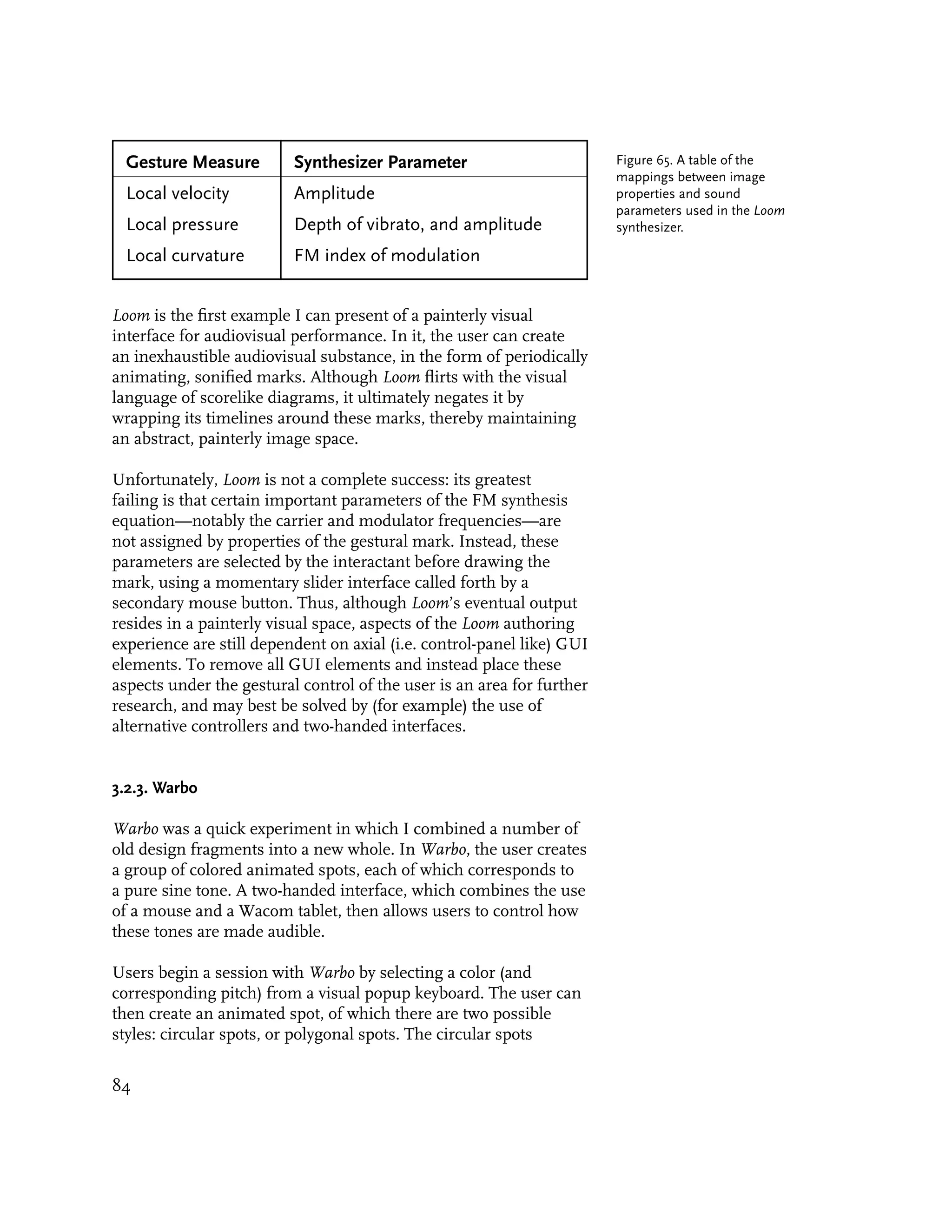
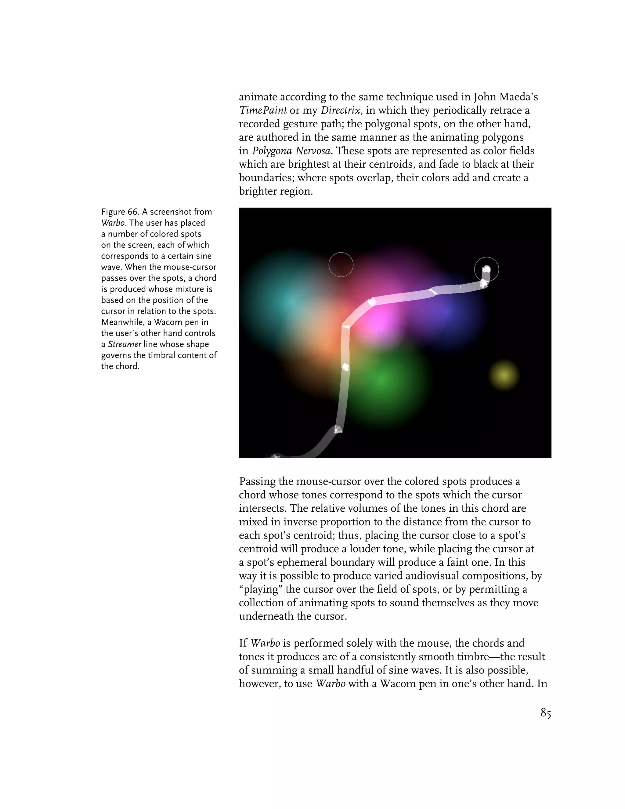
![this case, the pen controls a second, independent cursor; drawing Figure 67. The waveshaping
with the pen brings to life a Streamer trail (see Section 3.1.1) whose synthesis used in Warbo. A
pure cosine source wave in
shape is used to govern the timbre of the chord played by the the lower left is shaped by
user’s other hand. one of the Chebyshev shaping
functions, 4x3 - 3x, in the upper
The Streamer trail modulates the timbre of the user’s chord left. The final output wave is
shown in the upper right.
according to an audio synthesis technique called nonlinear
waveshaping. This technique was first developed by Jean-Claude
Risset in the late 1960’s, and is musically interesting because, as
in FM synthesis, it provides a simple handle on the time-varying
spectrum and bandwidth of a tone in a computationally efficient
way [Roads 1996]. According to Curtis Roads, the fundamental
idea behind waveshaping is to pass a sound signal x through
a distorting function w (also called the shaping function), which
maps any input value x in the range [-1, +1] to an output value
w(x) in the same range. If the shaping function w is a straight
diagonal line from -1 to +1, the output of w is an exact replica of
its input x. If it is anything else, however, then x is distorted by the
shaping function w, producing an enormous variety of musically
useful results.
Warbo uses a special class of waveshaping functions called Figure 68: A table of the first
Chebyshev polynomials, which have the special property that each seven Chebyshev waveshaping
polynomial only emphasizes a specific harmonic of the x input functions:
wave. As a result, the use of Chebyshev shaping functions T0 = 1
produces predictable, band-limited, well-behaved results. In T1 = x
Warbo, the curvature of each segment in the Streamer trail is T2 = 2x2 - 1
mapped to the amount of a given Chebyshev waveshaper that is T3 = 4x3 - 3x
T4 = 8x4 - 8x2 + 1
applied to the current musical chord. As the shape of the trail T5 = 16x5 - 20x3 + 5x
evolves in response to the user’s gesture, shimmering harmonics T6 = 32x6 - 48x4 + 18x2 - 1
brighten or dull the chord. In this way the mouse-hand controls
the current pitch(es) and volume(s), while the pen-hand controls Chebyshev polynomials are
the timbre. defined by the recurrence
relationship:
Tn+1(x) = 2xTn(x) - Tn-1(x).
Warbo is another example of an environment in which a
user can create and manipulate an inexhaustible, dynamic
audiovisual substance. Nevertheless, although Warbo produces
musically interesting and expressive results, its visual dimension
is something of an aesthetic hodge-podge: the visual relationship
between its Streamer trail and its colored spots, for example,
seems unmotivated. I include Warbo in this chapter because,
although it was quickly hacked together from older components,
its use of a two-handed interface points the way towards the future
direction of this work. Warbo’s greatest contribution is precisely
86](https://image.slidesharecdn.com/painterlyinterfacesforaudiovisualperformance-110920201619-phpapp01/75/Painterly-interfaces-for-audiovisual-performance-86-2048.jpg)
![that each hand can control different and complimentary aspects of
an audiovisual expression.
3.2.4. Aurora: a “Swirling Cloud of Shimmering Gas”
3.2.4.1. Origins
In January of 1999 I began to study the means by which dynamic
graphical lines might become able to convey a plausible sense of
physicality. After some experimentation I developed a model for
representing the underlying structure of “physical” lines, in which
Figure 69. The inner mechan- a finite-element, mass-spring-damper simulation is composed of
ics of a finite-element model virtual particles connected by alternating linear and torsional
for physically simulating a hair- springs. The model I developed has the effect of simulating the
like filament: linear springs
alternate with torsional ones.
tensile properties of thin physical filaments, such as hairs or
twigs.
Figure 70. A portrait of my
colleague Paul Yarin created
with Brillo. In the Brillo system,
hairlike filaments descend or
ascend gradients of brightness
in a grayscale photograph.
I developed two reactive drawing systems, Brillo and Floccus,
which permit a user to construct images out of lines structured
according to this physical simulation. In Brillo, lines drawn by
the user are buffeted by forces derived from a hidden but underly-
ing photograph. Light-colored filaments are attracted to bright
regions of the photograph, while dark filaments are attracted
to dark regions. I used these simple rules to coalesce piles of
casual scribbles into several portraits of my colleagues. The results
are wispy, organic and sometimes unsettling transformations:
chiaroscuros in hair. Later, I learned that a similar technique, of
compelling lines to perform lateral gradient descents on an image,
had been developed as an edge-detection algorithm in the field
of computer vision, where the method is called active contours or
snakes [Kass 1987].
87](https://image.slidesharecdn.com/painterlyinterfacesforaudiovisualperformance-110920201619-phpapp01/75/Painterly-interfaces-for-audiovisual-performance-87-2048.jpg)
![While Brillo was chiefly intended as a filter for photographic
images, the software application Floccus was designed less for the
sake of its final product—gooey balls of simulated hair—than for
the enjoyable process of its interaction. In Floccus (the name is
a Latin term for “hairball”), ductile filaments drawn by the user
swirl around a shifting, imaginary drain centered at the user’s
cursor. The force mechanism which propels the filaments is based
on a simplified model of gravity and is similar to that used
in Scott Snibbe’s Gravilux: an attractive force centered at the
cursor attracts the simulation’s particles with a strength inversely
proportional to the square of the particles’ distance [Snibbe and
Levin 2000]. Whereas Snibbe’s particles dramatically “slingshot”
the cursor’s location, however, filament elements in Floccus
lines are so strongly coupled to one another by their own
spring forces that they cannot overshoot the cursor without
mutual interference. Instead—torn by conflicting impulses to
simultaneously preserve their length, yet also move towards or
away from the cursor—the filaments find an equilibrium by
forming gnarly, tangled masses.
Figure 71. Simulated filaments
in Floccus form tangled masses
of curly hair.
One day in February 1999, while playing with the Floccus without
my eyeglasses on, it occurred to me that the density map of
Floccus’ constituent particles might itself make an interesting
display. Thus was born Aurora, a reactive system whose structural Figure 72. A line and its density
field. Note how the field is
“underpainting” is a floccular simulation, but whose visual
darker where the line is coiled;
display consists instead of a blurry, shimmering, nebulous cloud. this is a region of greater line-
Aurora’s glowing formlessness rapidly evolves, dissolves and length per unit area.
disperses as it follows and responds to the user’s movements.
88](https://image.slidesharecdn.com/painterlyinterfacesforaudiovisualperformance-110920201619-phpapp01/75/Painterly-interfaces-for-audiovisual-performance-88-2048.jpg)
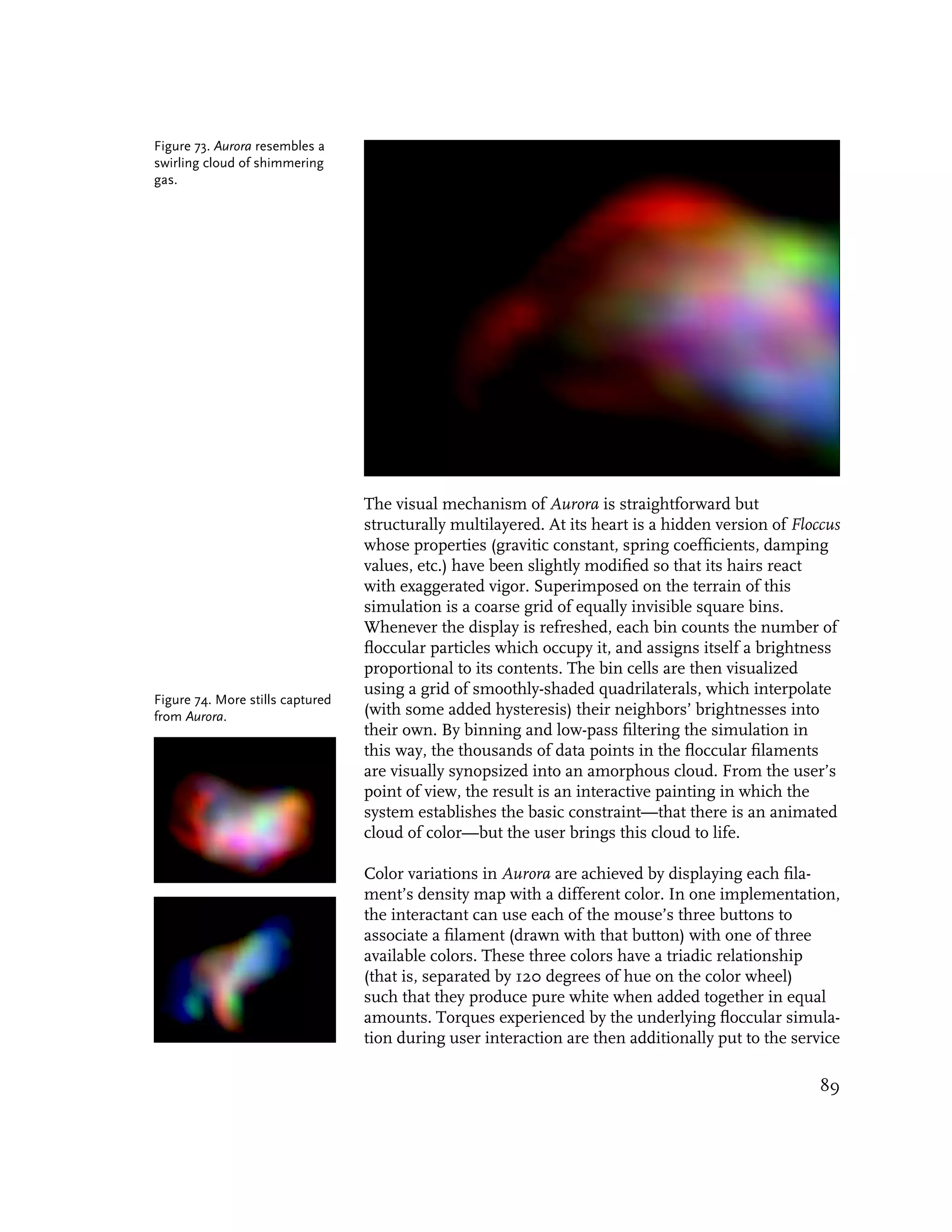
![of rotating the system’s color triad through the hue-space of the
color wheel. It is possible to create nearly any color of cloud by
carefully selecting and balancing the proportions of the colored
strokes, “tuning” the colors if so desired by applying twirling
forces to the simulation.
3.2.4.2. Sonification
The sonification of Aurora was undertaken in March of 2000,
and was inspired by Curtis Roads’ magnificent cookbook of digital
audio techniques, his Computer Music Tutorial [Roads 1996].
Scanning through Roads’ book, I was struck by what seemed to
be fertile similarities between Aurora’s floccular simulation and
an audio technique called granular synthesis, in which a complex
sound is built up from thousands of minute sound particles.
Curtis Roads explains granular synthesis thus:
“Granular synthesis builds up acoustic events from thousands of
sound grains. A sound grain lasts a brief moment (typically 1
to 100 milliseconds), which approaches the minimum perceivable
event time for duration, frequency, and amplitude discrimination.
Granular representations are a useful way of viewing complex
sound phenomena—as constellations of elementary units of
energy, with each unit bounded in time and frequency....The
grain is an apt representation for sound because it combines time-
domain information (starting time, duration, envelope shape) with
frequency-domain information (the period of the waveform inside
the grain, spectrum of the waveform)” [Roads 1996].
Figure 75. An example of a
simple sonic grain, consisting
Roads’ description of granular synthesis suggested a self-evident of a sinusoidal tone-burst
yet provocative opportunity to create a mapping between Aurora’s whose amplitude has been
underlying floccular simulation—which can consist of as many enveloped by a Hanning
as thirty thousand interconnected filament particles—and the (cosine) window.
thousands of sound-particles typically used in the granular
synthesis technique. I chose to implement a straightforward
variety of the technique called Quasi-Synchronous Granular
Synthesis (QSGS), which generates one or more streams of grains,
one grain following another, with a variable delay between the
grains [Roads 1996]. I decided to associate each stream of sound
grains with one of the floccular filaments produced by a user’s
gesture. Then I set about the problem of finding satisfactory,
and hopefully well-motivated, mappings between the granular
synthesizer’s control parameters and the knowable features of the
filaments’ particles.
Granular synthesis makes a vast, malleable sonic terrain available
to the instrument designer, at the cost of requiring the designer
90](https://image.slidesharecdn.com/painterlyinterfacesforaudiovisualperformance-110920201619-phpapp01/75/Painterly-interfaces-for-audiovisual-performance-90-2048.jpg)
![to stipulate a correspondingly enormous number of synthesizer
control parameters. Roads observes: “If n is the number of
parameters for each grain, and d is the average grain density
per second of sound, it takes d * n parameter values to specify
one second. Since d typically varies between a few dozen and
several thousand, it is clear that for the purposes of compositional
control, a higher-level unit of organization for the grains is
needed” [Roads 1996]. Much of the granular synthesis literature
discusses techniques for higher-level organization based on the
idea of stochastic or statistical control. According to this schema, the
parameters of individual grains are specified by randomization
functions whose means, bounds and standard deviations are
precisely and tightly controlled by the user’s performance. The
Figure 76. A pictorial effect of statistical control, then, is the reduction of synthesizer
representation of granular control parameters from a few thousand per second to a
synthesis parameters. From
[Roads 1996]. considerably more manageable handful.
The decision to statistically control Aurora’s granular synthesizer
was only half of the solution towards the environment’s eventual
sonification. A second unanswered question was the problem
of how the behavior of the thousands of particles in Aurora’s
underlying floccular simulation could be synopsized in order to
control each grain’s handful of “knobs.” Some method of data
reduction was necessary. The solution I developed—in which
statistical measures drive statistical controls—became one of the
chief innovations of the Aurora synthesizer.
In Aurora, numeric measures derived from statistical analyses of
the floccular simulation are mapped to the statistical properties of
the randomization functions which govern the control parameters
of the granular synthesis engine. A clear example of this is
the manner in which the spatial distribution of the simulated
particles is used to control the stereo placement of sound grains.
Consider a relatively typical case in which the granular synthesizer
is producing ten simultaneous streams of grains, and the duration
of each grain is approximately 30 milliseconds. This means that
L R the synthesizer will generate 300 sound grains per second, or
mean
about 10 sound grains during each frame of animation (at 30
frames per second). The question is, how shall these 10 grains
standard deviation be positioned in the stereo field, such that the location of the
sound they produce during that frame is perceived to correspond
Figure 77. Mapping between with the visual cloud of particles? A simple answer would be
the spatial distribution of
to compute the horizontal centroid of the simulated particles,
particles, and the stereo
placement of sound grains. express that centroid as a percentage of the visual display’s width,
91](https://image.slidesharecdn.com/painterlyinterfacesforaudiovisualperformance-110920201619-phpapp01/75/Painterly-interfaces-for-audiovisual-performance-91-2048.jpg)
![Aurora Synthesizer Particle Simulation Property
Control Parameter
grain carrier center frequency Each grain’s carrier wave is assigned a pitch which falls within a specific
the mean frequency of the Gaussian distribution. This distribution’s mean is centered at the grain carrier
waveforms inside each grain. center frequency, and has a standard deviation equal to the grain carrier
bandwidth. The center frequency is functionally dependent on both the mean
velocity of a filament’s particles, and the average amount of distension
experienced by the filament’s linear springs. The effect is that a more vigorously
moving cloud of particles produces a generally higher-pitched sound.
grain carrier bandwidth The frequency range or grain carrier bandwidth is proportional to the standard
the range of possible deviation of the particle velocities, plus a small term proportional to the mean
frequencies within which the torque experienced by the particles. The effect is such that when there is a lot of
grains’ carrier tones vary, variation in how particles are moving, a greater variety of pitches are heard.
centered on the carrier center
frequency.
grain duration floor Each grain is a assigned a random duration. This duration can be as short as
the shortest possible duration the grain duration floor, or it can be as long as the floor plus the grain duration
of any grain. range. The floor is functionally related to a measure of the particles’ vigor, such
that a less vigorous cloud of particles will tend to produce grains which are
longer and more easily perceptible as discrete sonic events. The measure of
vigor is derived from a weighted combination of the particles’ mean velocity
and mean distension.
grain duration range The grain duration range is a function of the number of particles in each
the range within which the filament. Longer filaments produce a narrower range of durations. The effect is
grains’ durations may vary, that large clouds (those made from longer filaments) sound smoother, while
above the minimum grain smaller clouds sound more irregular in a manner which corresponds with their
duration. commensurately more visible inhomogeneities.
stereo placement Each grain’s stereo location is positioned within a Gaussian distribution whose
the left/right balance of a given first and second moments are exactly equal to the mean and standard deviation
grain’s position in the stereo of the particles’ horizontal positions in the floccular simulation.
field.
grain carrier waveform mixture Each grain’s carrier waveform can be a blend between a sine wave and a square
the relative mixture between a wave. The waveforms are assigned to be more squarelike in proportion to
sine wave and a square wave, the mean velocity of the particles in the simulation, thus producing spectrally
that a given grain’s carrier brighter sounds when the cloud of particles moves vigorously.
tone.
delay between grains The delay between grains is extremely short, and is slightly randomized in
the amount of time between order to prevent artifacts of over-regularity such as extraneous formants. The
the completion of one grain’s delay decreases mildly as the number of points in the simulation increases,
envelope and the onset of producing a smoother sonic texture for large clouds, and a more irregular
the subsequent grain in that texture for lumpy clouds. The effect of the irregular delay times is a controllable
stream. thickening of the sound texture through a “blurring” of the formant structure
[Roads 1996].
Figure 78. A table of the specific mappings between the analyzed simulation
measures, and the granular synthesis parameters, used in the Aurora synthesizer.
93](https://image.slidesharecdn.com/painterlyinterfacesforaudiovisualperformance-110920201619-phpapp01/75/Painterly-interfaces-for-audiovisual-performance-93-2048.jpg)
![we create mappings should be of approximately commensurate
dimensionality. With this principle in mind, I selected granular
synthesis as Aurora’s sonification technique because it produces
large-scale sonic events in an analogous way to that in which
Aurora’s graphic system generates macroscopic visual effects: by
aggregating the individual contributions of a myriad of infinitesi-
mal “atoms.”
Although the sheer numbers of floccular-simulation data points
and granular synthesis knobs were roughly commensurable, it
was nevertheless not possible, nor even sensible, to directly map
each number in the simulation to a specific numeric control in
the synthesizer: the fact remained that each body of variables
described a different domain—one of space, the other of time.
To bridge the two domains, I adopted the statistical distribution
as an intermediate representation. Although this representation
had the unfortunate effect of collapsing the dimensionality of
both the simulation’s information and the synthesizer’s control
parameters, it worked remarkably well at translating the subtle
dynamics of one domain into the behavior of the other. Aurora
achieves an extremely tight connection between sound and image
because the aggregate behaviors of both have been carefully
matched.
In sum, Aurora presents an audiovisual environment in which a
user is able to create and manipulate an inexhaustible, dynamic,
Figure 79. The relationship
particle simulation
of Aurora’s image and audio
generators to its underlying
particle simulation. The
functional couplet of [statistical
analysis] and [statistical control]
is used to conform the
dynamic behavior of the audio
to that of the visual simulation.
statistical analysis
binning and
statistical control lowpass filtering
audio cloud visual cloud
94](https://image.slidesharecdn.com/painterlyinterfacesforaudiovisualperformance-110920201619-phpapp01/75/Painterly-interfaces-for-audiovisual-performance-94-2048.jpg)
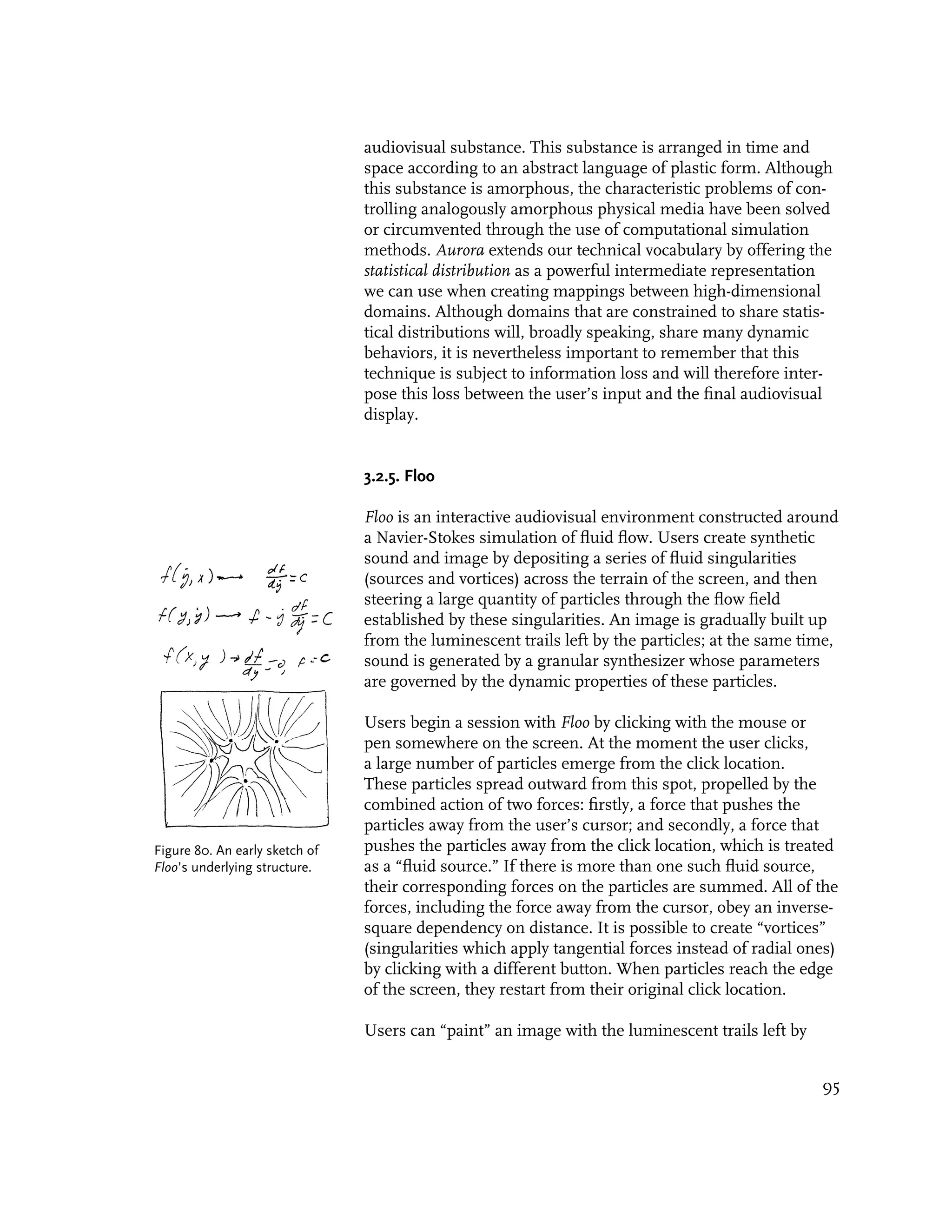
![Figure 81. A screenshot of Floo
in use.
the particles. The shapes of these trails are entirely a result of the
radial and tangential forces originating from the user’s cursor and
singularities. As the particles tread again and again over a given
location, that spot becomes brighter and brighter.
The sound in Floo is generated by a granular synthesizer.
Certain aspects of this synthesizer are similar to the granular
synthesizer used in Aurora; for example, all of the grains use
a Hanning window (a raised inverted cosine shape) for their
amplitude envelope. One difference, however, is the number of
simultaneous streams of sound grains: while Aurora allocates one
stream per filament (on the order of ten), Floo allocates one per
particle (on the order of hundreds).
The most important difference between the Floo and Aurora
granular synthesizers is the shape of the waveform with which
Floo fills its grains. While Aurora fills its grain envelopes with
simple waves like sine tones and square tones, Floo uses a unique
Figure 82. The spectrum
and complex kind of sound called a Shepard tone. Shepard tones amplitude envelope of Shepard
are a form of “audio illusion” discovered in the 1960s by Roger tones. As spectral component
Shepard, a research psychologist at the AT&T Bell Laboratories. amplitudes fall to zero (moving
According to Richard Moore, “these tones exhibit the peculiar either upward or downward)
at one end of the spectrum,
property of “circular pitch,” in the sense that if one constructs a
they are replaced by new ones
musical scale out of them, the notes eventually repeat themselves entering at the other end. From
when the notes are played consecutively upward or downward. [...] [Moore 1990].
96](https://image.slidesharecdn.com/painterlyinterfacesforaudiovisualperformance-110920201619-phpapp01/75/Painterly-interfaces-for-audiovisual-performance-96-2048.jpg)
![A visual analogy of Shepard tones might be the optical barber pole
C D illusion, in which helical stripes painted on a rotating cylinder
B appear to move up or down as the cylinder rotates without ever
moving off the ends of the pole” [Moore 1990]. Shepard tones can
E
thus be used to create the illusion of a continually increasing or
A
F continually decreasing pitch.
G
Floo’s granular synthesizer maps the orientation of a particle’s
Figure 83. Floo’s granular velocity to the pitch of a Shepard tone used in a stream of grains.
synthesizer maps a particle’s Thus, the sonified particles move in a seamlessly circular pitch
orientation to the pitch of a space. Particles which move in opposite or different directions will
Shepard tone in a grain. In this
way, the particles can move in a
create chords, while particles which move in similar directions
seamlessly circular pitch space. will create thick, chorused drones. This mapping and others are
discussed further in the table below.
Figure 84. A table of the specific mappings between the particle simulation and
the granular synthesis parameters used in the Floo synthesizer.
Floo Synthesizer Control Particle Simulation Property
Parameter
grain carrier pitch Each grain’s carrier wave is assigned a Shepard tone whose pitch in the tone
the apparent pitch of the wheel is directly derived from the orientation of the particle’s bearing. The effect
Shepard tone inside each is that the user can control the pitch of a particle by steering it in one direction
grain. or another.
grain duration The grain duration is a constant. The result of this is that the overall sound has
the duration of the grains. a dronelike quality, whose fundamental is a function of the grain duration, and
whose formants and harmonics are a function of the grain’s carrier wave.
stereo placement Each grain’s stereo location is positioned at its corresponding particles’
the left/right balance of a given horizontal position in the display.
grain’s position in the stereo
field.
delay between grains The delay between grains is extremely short, and is slightly randomized in order
the amount of time between to prevent artifacts of over-regularity such as extraneous formants.
the completion of one grain’s
envelope and the onset of
the subsequent grain in that
stream.
grain volume Each grain’s amplitude is functionally related to the speed of its corresponding
the amplitude of a given grain particle, as well as the distance from its particle to the cursor.
97](https://image.slidesharecdn.com/painterlyinterfacesforaudiovisualperformance-110920201619-phpapp01/75/Painterly-interfaces-for-audiovisual-performance-97-2048.jpg)
![used to represent the speed of the user’s trace, while Aurora brings
into relief those regions of the canvas to which the user has added
more material, while de-emphasizing the exact positions of the
user’s marks.
4.2. Challenges and Pitfalls.
In the course of surveying the current state of audiovisual
performance systems, and in developing the set of software
applications which support this thesis, I have come to identify a
set of challenges and pitfalls which seem to crop up again and
again in the design of such systems. Of course, it is not strictly
the case that my thesis applications succeed in avoiding all of
these pitfalls. In this section, I describe these snares, discuss the
examples in which my own applications succumb to them, and
make an effort, where possible, to suggest ways around them.
4.2.1. rANdOmNeSs
Of all of the pitfalls facing a designer of audiovisual performance
systems, the use of computationally-generated randomness is one
of the surest. John Maeda puts the matter plainly in Design by
Numbers, his primer for novice programmers:
“The amateur may be tempted by the cheap thrills of randomness.
Random numbers, noise, stochastics, or whatever you want to call
the complete lack of control that serves as the root of techno-styled
graphics, is a form of profanity that you should generally avoid.
But in many ways, resistance may prove futile because complete
control of a complex computational process is still something of a
faraway goal and the allure of randomness can be overpowering.
My personal philosophy has been that if you are going to use
randomness, you should at least know where it comes from.”
[Maeda 1999]
The appeal of randomness, in theory, is that it can be used to
introduce new “information” in order to keep an interaction fresh.
Unfortunately, the problem with randomness is that it contains
no information at all—and can therefore be misinterpreted as
actual information by an unsuspecting human user. The user
suffering from a random system may ask: “Did I just do x, or did
it just happen by itself?” “Am I controlling this, or is this behavior
a coincidence?” In such cases, randomness is a confusing
distraction which makes it more difficult for a user to understand
and master an interactive system. This is especially problematic
107](https://image.slidesharecdn.com/painterlyinterfacesforaudiovisualperformance-110920201619-phpapp01/75/Painterly-interfaces-for-audiovisual-performance-107-2048.jpg)
![non-orthogonal? The answer is of course that they can, because
these assignments are the completely arbitrary products of the
visual language of diagrams. The commonplace decision to map
x or y input coordinates to simulation parameters is one which
relies on an abstract and artificial convention, rather than on
geometric intuitions that are more analogous to the natural world
[Snibbe and Levin 2000]. Although Cartesian coordinates may be
computationally and electromechanically convenient for input and
output on raster-based systems, the reactions and processes of
nature obey an organic logic which is often poorly described by
relationships to a Cartesian grid. In designing the systems which
support this thesis, I therefore adopted the more perceptually-
oriented primitives of pre-Cartesian geometry, such as direction,
velocity, orientation, and curvature, as the building blocks of these
environments. These primitives are “read” directly by the eye,
requiring no recourse to the labels of some axis for interpretation.
By basing the visual dynamisms and aural sonifications on these
intrinsic properties of gestural marks—as opposed to the extrinsic
properties of some axis or grid—an extremely tight relationship
between gesture, animation and sound can be the result.
Pitch is one of the most fundamental perceptual dimensions of
sound. Because the spectrum of audible pitch is continuous and
scalar, it is often convenient to map pitch to a linear axis in
physical and graphic interfaces. Such a design strategy, motivated
by basic physical principles (i.e., shorter strings and pipes produce
higher pitches) has become a de facto pattern for physical musical
instruments, and we therefore witness linearly-spatialized pitch
interfaces in almost all classes of musical devices, such as key-
boards, guitar necks, and the bores of wind instruments. Because
these traditions are so deeply ingrained, the search for alternative
interface organizations for pitch control is a difficult one. One
alternative that this thesis work points to, however, is the sub-
stitution of spatialized interfaces with temporalized ones. Thus
Aurora, for example, controls pitch with force and velocity—both
time-based quantities. And, in fact, there are precedents for this in
the real world, such as the holeless shakuhachi flute, on which dif-
ferent pitches are achieved by more forceful blowing. In mapping
parameters to temporal controls instead of spatial ones, lies the
possibility of freeing up the meaning-making affordances of the
visual space itself.
Of the five audiovisual systems presented in Chapter Three, only
one, Yellowtail, stoops to the use of an explicit, diagrammatic,
110](https://image.slidesharecdn.com/painterlyinterfacesforaudiovisualperformance-110920201619-phpapp01/75/Painterly-interfaces-for-audiovisual-performance-110-2048.jpg)
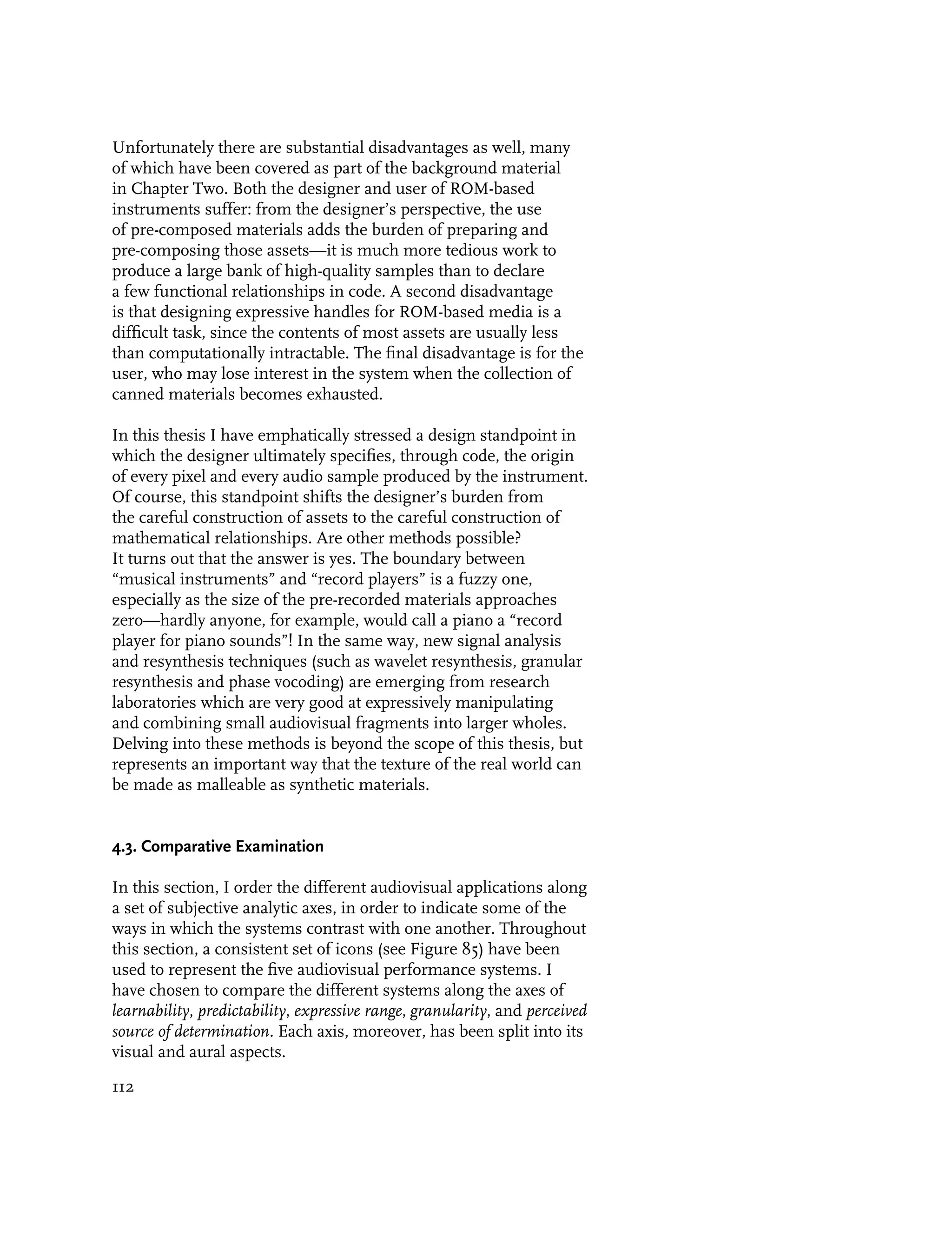
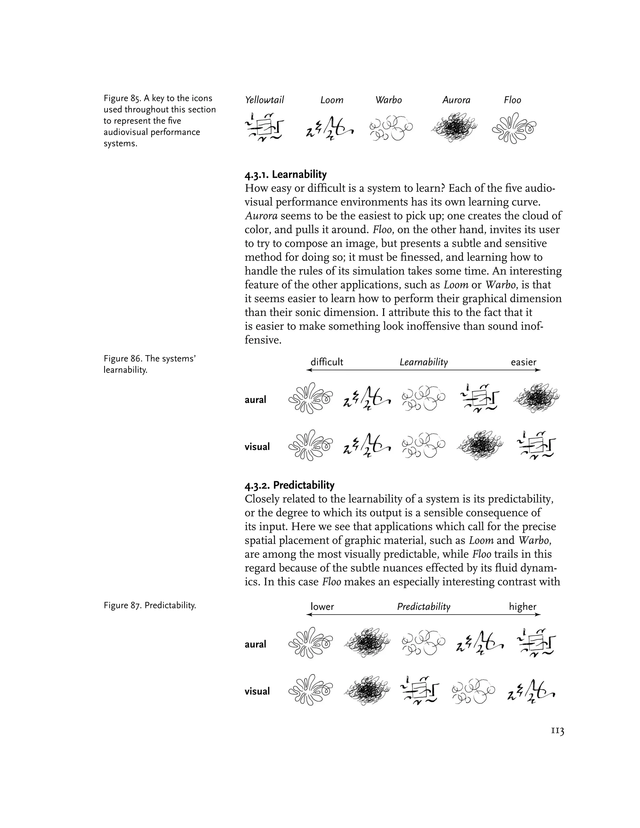
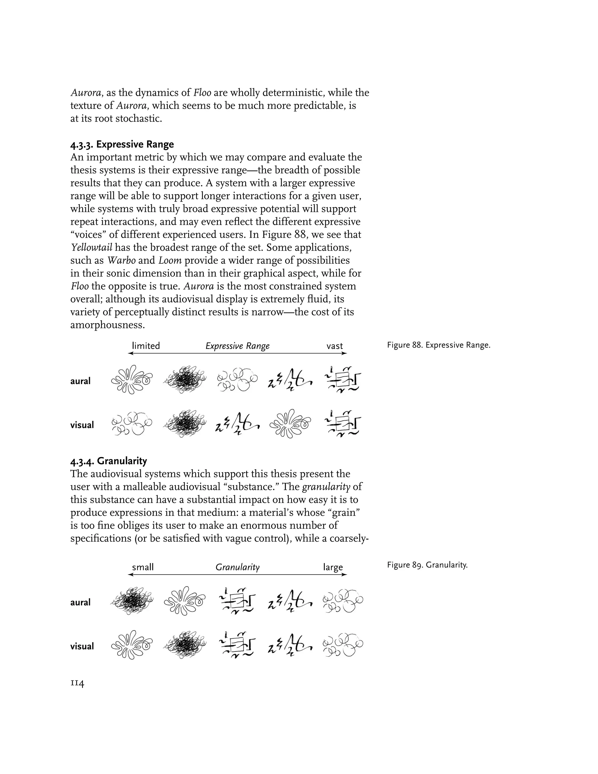
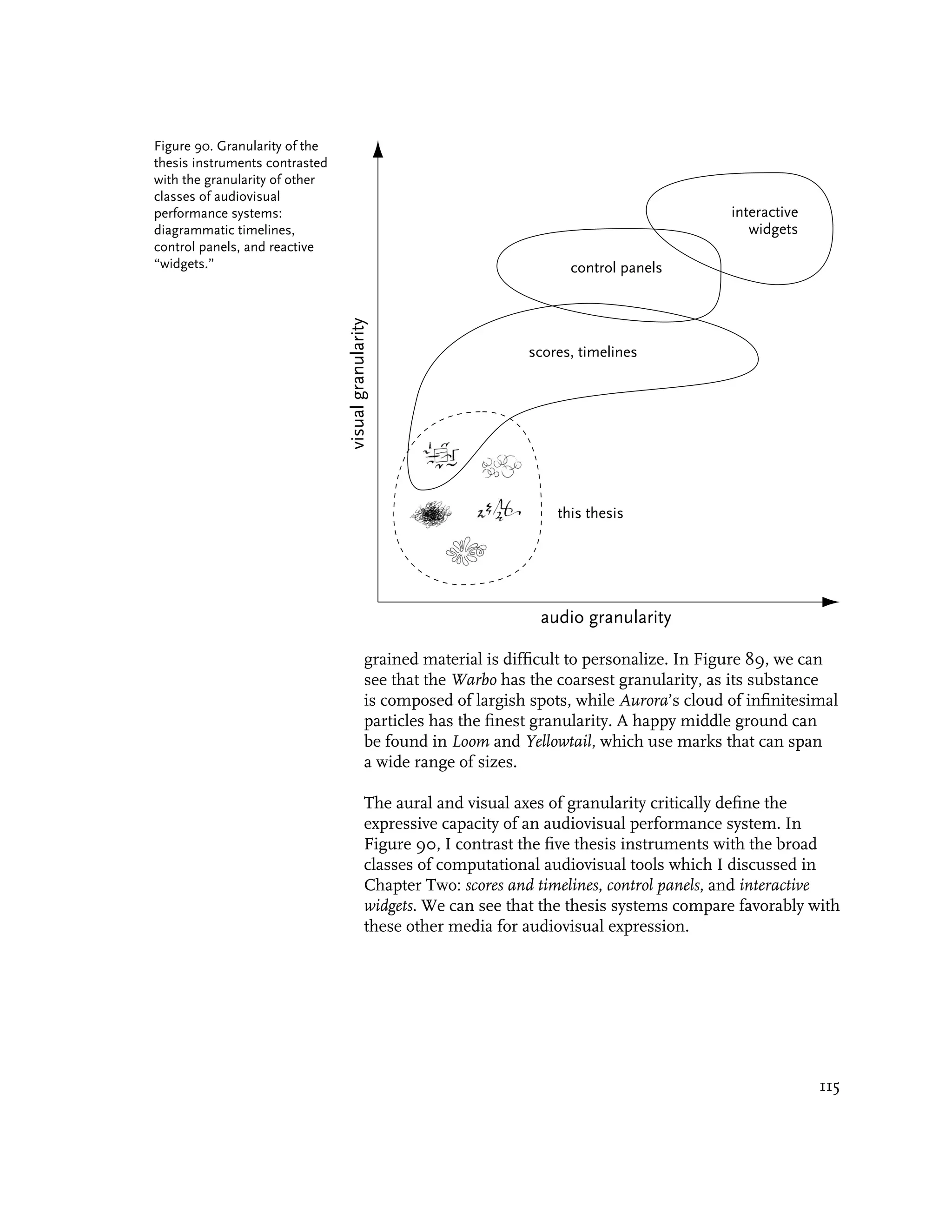
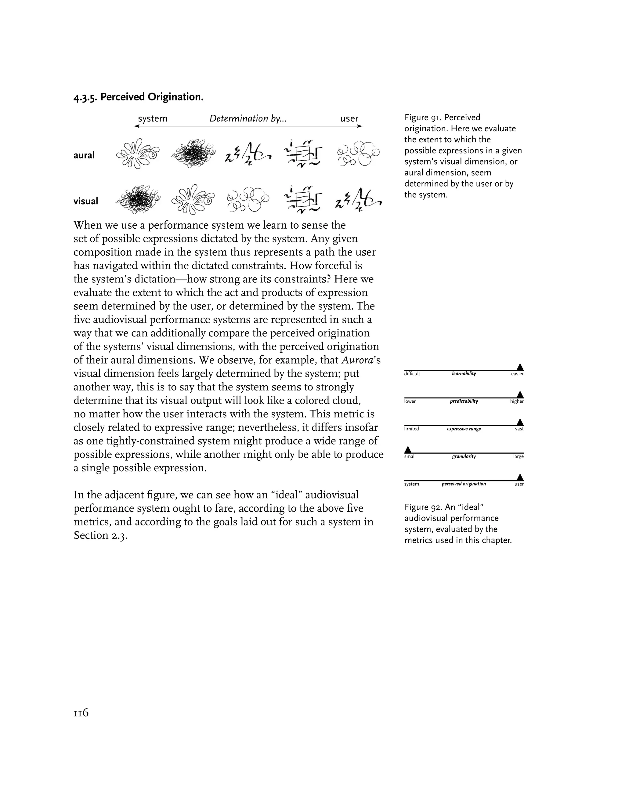

![Appendix A.
A Timeline of Instruments for Color-Music Performance
Date Inventor Device Description
1734 Louis-Bertrand Clavecin Oculaire Father Louis-Bertrand Castel, a Jesuit priest
Castel (1688-1757) and mathematician, designed and constructed
the first known “color organ”, his Clavecin
Oculaire (Ocular Harpsichord). Motivated by
both natural philosophy and a spiritual mys-
ticism, Castel augmented a traditional harp-
sichord with mechanically-exposed colored
tapes backlit by a series of candles. [Peacock
1988][Popper 1968]. A more complete descrip-
tion of Castel’s device is given in the body of
the thesis text.
1789 Erasmus Darwin oil-lamp device The physician and inventor Erasmus Darwin (a
(1731-1802) grandfather of Charles Darwin) suggested that
visual music could be produced by projecting
light from oil lamps through pieces of colored
glass [Peacock 1988].
1791 Karl von colored-liquid Karl von Eckartshausen, in his Disclosures of
Eckartshausen clavichord Magic from Tested Experiences of Occult Phil-
osophic Sciences and Veiled Secrets of Nature,
acknowledged the influence of Castel in his
design of a modified clavichord. Eckartshausen
wrote that he “had cylindrical glasses, about
half an inch in diameter, made of equal size,
and filled them with diluted chemical colors.
Behind these glasses I placed little lobes of
brass, which covered the glasses so that no
color could be seen. These lobes were con-
nected by wires with the keyboard of the clavi-
chord, so that the lobe was lifted when a key
was struck, rendering the color visible....The
clavichord is illuminated from behind by wax
candles. The beauty of the colors is indescrib-
able, surpassing the most splendid of jewels.
Figure 93. A schematic diagram of von Eckartshausen’s Nor can one express the visual impression
colored-liquid clavichord. awakened by the various color chords” [von
Eckartshausen 1791].
1844 D. D. Jameson colored liquid device Possibly inspired by Darwin or Eckartshausen,
Jameson’s instrument also filtered light
through “glass receptacles containing liquids
127](https://image.slidesharecdn.com/painterlyinterfacesforaudiovisualperformance-110920201619-phpapp01/75/Painterly-interfaces-for-audiovisual-performance-127-2048.jpg)
![of various colors,” and projected the resulting
colored light onto a wall covered with reflective
metal plates. In addition to developing the
device, Jameson also published a pamphlet,
“Colour-Music,” in which he described a
system of notation for the new art form
[Popper 1968].
1869-73 Frederic Kastner Pyrophone; Singing Frederic Kastner’s 1869 Pyrophone produced
Lamp both sound and image by opening flaming
gas jets into crystal tubes. Essentially a
gas-activated pipe organ, the device made
sounds comparable to “the human voice,
the piano, and even the full orchestra.” His
larger Singing Lamp, made in 1874, added
an electrical actuation mechanism to the
Pyrophone, permitting the instrument to be
played from a considerable distance away
[Popper 1968].
Figure 94. Kastner’s
Pyrophone. From
[Popper 1968].
128](https://image.slidesharecdn.com/painterlyinterfacesforaudiovisualperformance-110920201619-phpapp01/75/Painterly-interfaces-for-audiovisual-performance-128-2048.jpg)
![1877 Bainbridge Bishop color organ Bainbridge Bishop was an American interested
in the concept of “painting music.” He
modified a small pipe organ, such that
combinations of colored light were rear-
projected onto a small screen when music was
performed. His projections used daylight at
first, and later an electric arc. [Peacock 1988]
[Popper 1968].
Figure 95. Bishop’s
color organ. From
[Popper 1968].
1893 Alexander Wallace Color Organ It is to the British painter Alexander Wallace
Rimington Rimington that we owe the term “color organ”,
(1854-1918) which he patented along with his device
in 1893. He later described its mechanism
(essentially a bellows organ coupled to an
electric colored light projection system) in
his 1911 book, Colour-Music: The Art of
Mobile Colour. Rimington had considerable
success in concert halls with his color-music
performances of compositions by Wagner,
Chopin, Bach and Dvorak [Popper 1968].
In the design of his instruments, according
to [Peacock 1988], “Rimington was keenly
aware of the ‘executant’, and wished to
create instruments that could be played in
performance as well as composed for. Form
played little role in Rimington’s work; he
recognized it as a factor that might be
explored, but felt that colour by itself could be
satisfying for an immense number and variety
of compositions.”
129](https://image.slidesharecdn.com/painterlyinterfacesforaudiovisualperformance-110920201619-phpapp01/75/Painterly-interfaces-for-audiovisual-performance-129-2048.jpg)
![1895 William Schooling vacuum-tube William Schooling constructed a device in
instrument which the illumination of variously-shaped
vacuum tubes was controlled with a keyboard
and set of foot-pedals [Peacock 1988].
1911 Alexander Scriabin Tastiera per Luce For his symphony Poem of Fire (Prometheus),
(1872-1915) the Russian composer Alexander Scriabin
devised an accompaniment of changing
colored lights. Scriabin’s score called for a
keyboard-based color organ he named the
Tastiera per Luce, which was probably based
on the design of Rimington’s instrument.
Scriabin wanted everyone in the audience
to wear white clothes so that the projected
colors would be reflected on their bodies and
thus possess the whole room [Moritz 1997].
Unfortunately, Scriabin was disappointed by
the performances of the Poem of Fire, owing
to the deplorable state of the light projectors
available at the time [Gerstner 1968], [Peacock
1988], [Popper 1968].
1912 Alexander Hector sound-color Referenced in [Peacock 1988].
instrument
1915 Modest Altschuler Chromola Referenced in [Peacock 1988].
and Preston S. Millar
1919 Thomas Wilfred Clavilux Thomas Wilfred completed his first
(1889-1968) instrument for the production of visual
compositions in 1919. He called his
instrument the Clavilux, and chose the term
“lumia” to describe the new art form of silent
color-music projections. More information
about Wilfred and his instruments is provided
in the thesis text [Scattergood-Moore 1998].
Figure 96. Images produced by
a Wilfred Home Clavilux. From
[Scattergood-Moore 1998].
130](https://image.slidesharecdn.com/painterlyinterfacesforaudiovisualperformance-110920201619-phpapp01/75/Painterly-interfaces-for-audiovisual-performance-130-2048.jpg)
![1919 Mary Hallock- Sarabet; Visual-Music Mary Hallock Greenewalt was a classically-
Greenewalt Phonograph trained pianist with an illustrious concert
career, before her desire to control the
ambience in a concert hall led her to
experiment with light modulation. Greenewalt
was chiefly interested in how variations in
luminosity could parallel nuances in music,
and so she designed a large color-organ, the
Sarabet, to put 1500 watts of power at the
service of up to 267 shades of color [Popper
1968]. According to historian William Moritz,
Greenewalt “invented the rheostat in order to
make smooth fade-ups and fade-outs of light,
and the liquid-mercury switch, both of which
have become standard electric tools. When
other people (including Thomas Wilfred)
began infringing on her patents by using
adaptations of the rheostat and mercury
switch, she tried to sue, but a judge ruled that
these electric mechanisms were too complex
to have been invented by a woman, and
denied her case.” [Moritz 1997] Although she
was unquestionably a victim of foul play,
Greenewalt’s claims show that she may have
also been unfamiliar with her history, for on
the general matter of an instrument for color-
Figure 97. Mary Hallock Greenewalt
with her Visual-Music Phonograph music, she wrote in her 1946 book, “It is
(1919). Photo by Shewell Ellis. I who conceived it, originated it, exploited
it, developed it, and patented it.” [Greenewalt
1946]. Greenewalt continued to accompany
orchestras on her Sarabet for many years,
during which time she designed a special
notation system that recorded the intensity and
deployment of various colors during any given
musical composition.
1920 Wladimir Baranoff- Piano Optophonique The Ukrainian artist Wladimir Baranoff-
Rossiné (1888-1944) Rossiné appears to have been largely
overlooked in the English-language literature
on color organs. Around 1916, Baranoff-
Rossiné began development of his Piano
Optophonique, a light-projection performance
machine. Baranoff-Rossiné’s machine
operated by passing a bright white light
through a variety of keyboard-controlled
Figure 98. Images produced by the
“luminous filters: simply coloured ones;
Piano Optophonique.
optical elements such as prisms, lenses or
mirrors; filters containing graphic elements
and, finally, filters with coloured shapes
131](https://image.slidesharecdn.com/painterlyinterfacesforaudiovisualperformance-110920201619-phpapp01/75/Painterly-interfaces-for-audiovisual-performance-131-2048.jpg)
![and defined outlines.” At the heart of the
instrument were a series of “Optophonic
Disks”: circular glass filters covered by
translucent paintings, and made to spin
inside the projector by the action of electric
motors. The machine’s resulting projections
are lush and kaleidoscopic. Baranoff-Rossiné
gave notable Optophonic performances at the
Meyerhold (Berlin) and Bolshoi (Moscow)
theaters in 1924, and at the Parisian Studio
des Ursulines theater in 1928. The Piano
Optophonique stands out as important because
of the interesting relationship it establishes
between the freedom afforded by its
Figure 99. The Piano Optophonique. improvisational controls, and the immutable
From [Baranoff-Rossiné 1997]. playback of its pre-recorded optical media.
[Baranoff-Rossiné 1997], [Gerstner, 1986],
[Popper 1968].
1922 Ludwig Hirschfeld- colored shadow The Weimar Bauhaus of the early 1920’s
Mack shows was a hotbed of experimentation in kinetic
sculpture. In the summer of 1922, Ludwig
Hirschfeld-Mack, Joseph Hartwig and Kurt
Schwerdtfeger developed a new mode of
expression involving mobile light bulbs of
different colors. Hirschfeld-Mack and his
group composed a number of scored shadow
show performances, such as his Lichtsonate
and Farbensonatine, which were accompanied
by piano music.[Peacock 1988], [Popper 1968].
1922 Kurt Schwerdtfeger Reflektorische Kurt Schwerdtfeger created his Reflektorische
Farblichtspiele Farblichtspiele at the Weimar Bauhaus. In
this system, “colored rays from mobile light
sources shone through forms cut in cardboard,
thus producing staggered projections on the
screen.” Schwerdtfeger evidently adapted his
instrument to both abstract and figurative
forms. [Popper 1968].
Figure 100. An image produced by
Schwerdtfeger’s instrument. From
[Popper 1968].
132](https://image.slidesharecdn.com/painterlyinterfacesforaudiovisualperformance-110920201619-phpapp01/75/Painterly-interfaces-for-audiovisual-performance-132-2048.jpg)
![1925 Sandor (Alexander) Sonchromatoscope In 1925, the Hungarian composer Alexander
Laszlo (1895-1970) Laszlo wrote a theoretical text on the
relationship of color to music, Die
Farblichtmusik, which became an influential
text among many European color-organ
designers [Popper 1968]. Laszlo also
constructed his own instrument, the
Sonchromatoscope, which contained switches
for colored spotlights and slide projections
on the stage above his piano. According
to William Moritz, “When the first reviews
complained that the visual spectacle was
much tamer than the Chopin-like dazzle
of Laszlo’s virtuoso piano compositions,
he contacted Oskar Fischinger to prepare
some filmed abstract images of greater
complexity and vibrancy. Fischinger prepared
a dazzling spectacle with three side-by-side
movie projections that were augmented by
two more overlapping projectors to add
extra colors to the finale, and some
complementary changing slide-projections
around the borders of the film projection.
Much to Laszlo’s chagrin, the reviews flip-
flopped: the astonishing visual imagery was
much livelier and more modern that the old-
fashioned Chopin-style piano music.” [Moritz
1997] In later decades, Laszlo became a well-
known composer of film and TV music,
including themes for Charlie Chan and Attack
of the Giant Leeches.
1927 Raoul Hausmann Optophone Raoul Hausmann, also known for his Dada
(1886-1971) poetry and writings, and husband for a time
of photomonteur Hannah Höch, developed a
keyboard-based Optophone in the early 1920’s.
[Popper 1968].
Figure 101. Hausmann’s
drawings for his Optophone.
133](https://image.slidesharecdn.com/painterlyinterfacesforaudiovisualperformance-110920201619-phpapp01/75/Painterly-interfaces-for-audiovisual-performance-133-2048.jpg)
![1928 Zdenek Pesanek colour keyboard Zdenek Pesanek, a Czech master of glass
(1896-1965) sculpture, was also interested in light-play and
worked on a color keyboard during the 1920’s
[Popper 1968].
1930 Baron Anatol Chromatophon Referenced in [Moritz 1997].
Vietinghoff-Scheel
1930 Laszlo Moholy-Nagy Lichtrequisit (Light- Moholy-Nagy’s Light-Space Modulator is an
(1895-1946) Space Modulator) important work of performable kinetic art,
which is still performed regularly at the
Harvard art museum where it resides. The
sculpture is a twofold installation piece: on
the one hand, it could function as a self-
contained installation, “to be enclosed in a
box with an opening through which spectators
could look at the lighting effects within.
On the other hand, it functioned as an
interactive, site-modifying work, transforming
its surroundings with revolving rays of
projected and filtered light.” [Malina 1974].
Figure 102. Moholy-Nagy’s
Light-Space Modulator.
1930s George Hall Musichrome According to [Peacock 1988], Hall created a
Musichrome device which used eight keys to
control two sets of four colors each.
1931 Morgan Russell Kinetic Light Machine Morgan Russell and Stanton Macdonald-
(1886-1953) and Wright, abstract painters, experimented with
Stanton Macdonald- their Kinetic Light Machine as a way of
Wright (1890-1972) animating “synchromies,” their own term for
color harmonies [Kushner 1990].
134](https://image.slidesharecdn.com/painterlyinterfacesforaudiovisualperformance-110920201619-phpapp01/75/Painterly-interfaces-for-audiovisual-performance-134-2048.jpg)
![1933 Adrien-Bernard color projector Klein’s book Colour-Music: The Art of Light,
Klein written in 1927, is a classic text on the
subject [Klein 1927]. Klein felt strongly that the
frequencies of colored light “provide a scale of
wave lengths whose ratios may be compared
directly to the twelve equally spaced intervals
of the chromatic scale.” According to [Popper
1968], Klein put his theories into practice a
few years later, with the design of a “colour
projector for the theater...Klein gave showings
of his projections in 1993 at the Astoria
Cinema, London.”
1940’s Cecil Stokes Auroratone films Stokes designed special time-lapse devices to
(1910-1956) capture the color effects of crystal formations
as they grew under polarized light. He
accompanied his films with “slow sedative and
mildly sad music,” and hoped that his films
would help mentally ill souls “ventilate their
pent-up tensions resulting from conflicts and
frustrations” [Collopy 1999].
1940’s Charles Dockum MobilColor Projector Charles Dockum began to build color-organs
in the late 1930s. His MobilColor Projector was
capable of producing both hard-edged or soft
imagery, since it used prepared image sources;
the movements and colors of these elements,
moreover, could be “programmed” in advance
to produce complex temporal patterns [Russet
& Starr 1988]. A later, larger version of
the MobilColor permitted multi-layered motion
in several directions, but met with practical
difficulties because its use demanded two
Figure 103. An image produced by
operators [Moritz 1997]. More information on
Dockum’s MobilColor Projector.
Dockum’s work is included in Chapter Two.
1950 Oskar Fischinger Lumigraph Oskar Fischinger’s career in abstract moving
(1900-1967) images spanned several decades. Although
he was chiefly known for his animation,
Fischinger’s ingeniously simple Lumigraph
stands as a monumental statement about the
degree of subtlety and expressivity attainable
with a visual performance device. A more
complete description can be found in Chapter
Two of the thesis text.
Figure 104. An image produced by
Fischinger’s Lumigraph.
135](https://image.slidesharecdn.com/painterlyinterfacesforaudiovisualperformance-110920201619-phpapp01/75/Painterly-interfaces-for-audiovisual-performance-135-2048.jpg)
![1953 Gordon Pask and Musicolour Machine Gordon Pask was a cybernetician concerned
McKinnon Wood with the psychology of aesthetic pleasure.
Between 1953 and 1957, Pask and his
collaborator McKinnon Wood designed a
Musicolour Machine that used musical input to
create visual output. By incorporating simple
“learning” strategies (automatic parameter
adjustment) into their machine, Pask and
Wood were able to investigate human
performers, and audiences, in cybernetic
feedback loops [Pask].
1956 Nicholas Schöffer Musiscope Schöffer’s Musiscope was an instrument for
(1912-) performing visual music, operated by an
electronic keyboard. Schöffer described his
machine as having “a complete range of
buttons...[which] enable the performer to
obtain on the screen -- simultaneously or
successively -- a considerable number of
families of images, colours and light effects,
and to combine them or vary their degree of
definition or intensity. Besides this, there is
a rheostat which works upon the respective
speeds of rotation of the coloured filters and
the sculptural element, allowing the enactment
of the images in time to accelerate, slow down,
or stop completely.” [Popper 1968].
1957-61 Jordan Belson Vortex Concerts According to William Moritz, “the composer
(1926-) and Henry Henry Jacobs convinced the Morrison
Jacobs Planetarium in San Francisco to let him use
their newly renovated four-track surround-
sound system for a series of concerts.
Jacobs commissioned new pieces of electronic
music from international composers and asked
Jordan Belson to prepare visual imagery that
could be projected on the dome during each
number. Having access to the planetarium
“starscape” projectors, as well as conventional
film and slide projectors, opened for Belson
the possibility of rivaling Thomas Wilfred’s
light projections, which had impressed him
years earlier in New York.” [Moritz 1996].
Figure 105. A still from one of
Belson’s Vortex Concerts.
136](https://image.slidesharecdn.com/painterlyinterfacesforaudiovisualperformance-110920201619-phpapp01/75/Painterly-interfaces-for-audiovisual-performance-136-2048.jpg)
![1960’s Lloyd G. Cross Sonovision The holographer Lloyd Cross was quick
to see the visual-music potential of the
newly-invented laser in the late 1960’s.
His Sonovision system for the visual display
of sound directly coupled the mechanical
deflection of a laser beam to audio pressure
variations. In this device, a thin flexible
membrane was stretched over the front of an
ordinary audio speaker cone; a small Mylar
mirror was then cemented in the center of the
membrane. When a laser beam was reflected
off the mirror, the result was a complex set
of highly responsive Lissajous-type figures, in
sync with the music, cast on the walls and
ceiling. [Malina 1974][Fairstein 1997].
1963 Frank Malina Lumidyne, Frank Malina developed a number of systems
(1912-1981) Reflectodyne in the 1960’s to explore dynamic lightforms.
The Lumidyne and Reflectodyne were
manipulable kinetic sculptures which
modulated light with a set of rotating painted
acrylic disks. Frank Malina was also notable as
an historian of kinetic art and as the founder
of the Leonardo journal of arts and sciences.
[Popper 1968],[Malina 1974].
1966 Richard I. Land Chromara Land’s easy-to-reproduce Chromara color organ
became one of the “standard” designs
popularized in ‘Sixties psychedelic culture.
His device applied a bank of differently-tuned
passband filters to incoming audio, and used
the responses of the filters to determine the
intensity of a corresponding set of colored
lights. Land’s writings further proposed the
introduction of manual controls and rhythm-
sensing circuits. [Malina 1974].
1974-79 Laurie Spiegel VAMPIRE Laurie Spiegel at Bell Labs created VAMPIRE
(Video and Music Program for Interactive
Realtime Exploration), a performance system
for the simultaneous synthesis of video images
and electronic sound. Spiegel’s system built on
the GROOVE computer music system created
by Max Matthews, by combining it with paint-
program-like graphic algorithms by Kenneth
Knowlton. The VAMPIRE system offered real-
time, gestural control of both sound and video
image, through a variety of continuous input
Figure 106. Laurie Spiegel
with the VAMPIRE system.
devices [Spiegel 1998].
137](https://image.slidesharecdn.com/painterlyinterfacesforaudiovisualperformance-110920201619-phpapp01/75/Painterly-interfaces-for-audiovisual-performance-137-2048.jpg)

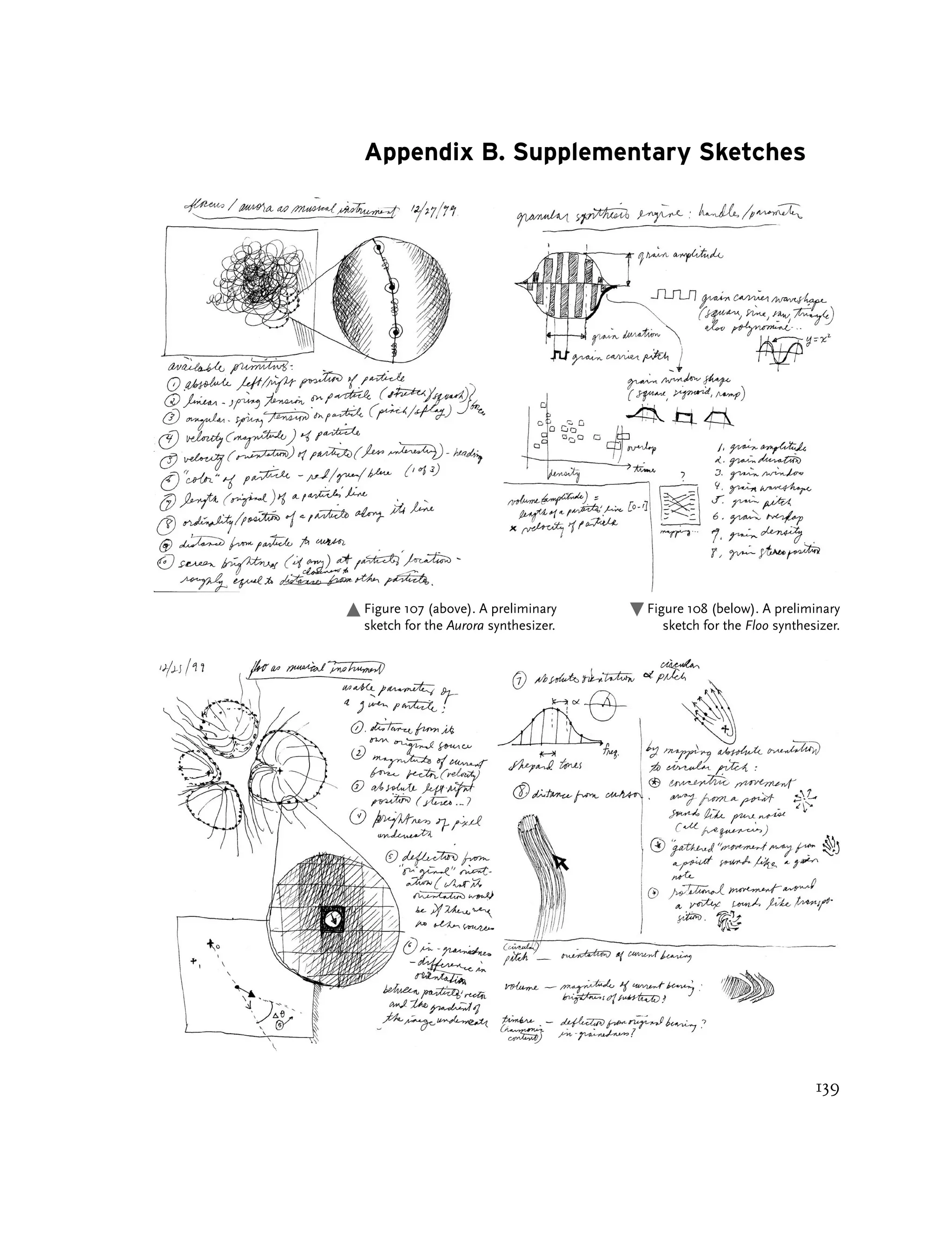

![C.1. Additive Synthesis in Yellowtail
int nsam = numberOfSamplesInOutputBuffer;
bool soundThreadActive; // whether we’re making sound
oat sampleRate; // samples per second, e.g. 44100
oat curTime; // current time, in seconds
int nosc = number of additive synthesis oscillators
oat noct = number of octaves of oscillators
oat lowf = lowest oscillator frequency
oat base = noct/nosc;
do {
if (determineIfSoundBufferNeedsFilling()){
for (int s=0; s<nsam; s++){
oat output = 0;
for (int i=0; i<nosc; i++){
oat amp = brightness of pixel[i]; // 0...1
oat freq = lowf * pow (base, i);
output += amp * sin(twoPi * freq * curTime);
}
soundOutputBuffer[s] = output;
curTime += (1.0/sampleRate);
}
}
} while (soundThreadActive);
C.2. FM Synthesis in Loom
int nsam = numberOfSamplesInOutputBuffer;
bool soundThreadActive; // whether we’re making sound
oat sampleRate; // samples per second, e.g. 44100
oat curTime; // current time, in seconds
int nstr = numberOfActiveLoomStrokes;
oat val;
// each Loom stroke has a carrier frequency and a
// modulator frequency associated with it by the user
do {
if (determineIfSoundBufferNeedsFilling()){
for (int s=0; s<nsam; s++){
oat output = 0;
for (int i=0; i<nstr; i++){
oat I = stroke[i]->getCurrentCurvature();
oat A = stroke[i]->getCurrentPressure();
oat C = stroke[i]->carrierFrequency;
oat M = stroke[i]->modulatorFrequency;
// the FM equation is A*sin(Ct + I*sin(Mx))
val = A* sin ( C*twoPi*curTime +
I*sin(M*twoPi*curTime));
output += val;
}
soundOutputBuffer[s] = output;
curTime += (1.0/sampleRate);
}
}
} while (soundThreadActive);
142](https://image.slidesharecdn.com/painterlyinterfacesforaudiovisualperformance-110920201619-phpapp01/75/Painterly-interfaces-for-audiovisual-performance-142-2048.jpg)
![C.3. Granular Synthesis in Aurora and Floo
int nsam = numberOfSamplesInOutputBuffer;
bool soundThreadActive; // whether we’re making sound
oat sampleRate; // samples per second, e.g. 44100
oat curTime; // current time, in seconds
int ngrn = numberOfActiveGrains;
do {
// update the status of each grains
for (int g=0; g<ngrn; g++){
bool grainFinished = ((curTime - grain[g]->startTime) >
grain[g]->duration);
if (grainFinished) {
grain[g]->setDurationBasedOnGraphics();
grain[g]->setFrequencyBasedOnGraphics();
grain[g]->setPanBasedOnGraphics();
grain[g]->setStartTime(curTime);
}
}
// generate audio samples from grains
if (determineIfSoundBufferNeedsFilling()){
for (int s=0; s<nsam; s++){
oat output = 0;
for (int g=0; g<ngrn; g++){
oat envelopeLoc = (curTime - grain[g]->startTime)
/grain[g]->duration;
oat amp = hanningWindow (envelopeLoc);
oat freq = grain[g]->frequency;
oat grainOutput = amp * sin(twoPi*freq*curTime);
output += grainOutput;
}
soundOutputBuffer[s] = output;
curTime += (1.0/sampleRate);
}
}
} while (soundThreadActive);
C.4. Chebyshev Waveshaping Synthesis in Warbo
int nsam = numberOfSamplesInOutputBuffer;
bool soundThreadActive; // whether we’re making sound
oat sampleRate; // samples per second, e.g. 44100
oat curTime; // current time, in seconds
int nspt = numberOfActiveWarboSpots;
int nseg = numberOfStreamerSegments;
143](https://image.slidesharecdn.com/painterlyinterfacesforaudiovisualperformance-110920201619-phpapp01/75/Painterly-interfaces-for-audiovisual-performance-143-2048.jpg)
![do {
if (determineIfSoundBufferNeedsFilling()){
for (int s=0; s<nsam; s++){
oat output = 0;
for (int i=0; i<nspt; i++){
oat F = spotArray[i]->getPitch();
oat A = spotArray[i]->getCurrentAmplitude();
oat val = sin (F*twoPi*curTime);
for (int j=1; j<nseg; j++){
oat amp = streamerSegs[j]->getCurvature();
// amplitudes are scaled 0...1
val = Chebyshev(j, amp*val);
// the j’th Chebyshev waveshaping function,
// see Figure 68
}
output += A * val;
}
soundOutputBuffer[s] = output;
curTime += (1.0/sampleRate);
}
}
} while (soundThreadActive);
C.5. A Simple Spring
bool simulationIsActive;
oat initialPosition;
oat position = initialPosition;
oat velocity = initialVelocity;
oat damping = 0.975; // for example. must be < 1.0
oat mass = 1.0; // particle mass
oat K = 1.0; // spring constant
do {
// use Euler integration to move a springy particle.
oat distension = position - initialPosition;
oat force = K*distension; // Hooke’s Law: f=-kx
oat acceleration = force/mass;
velocity += acceleration; // integrate once
velocity *= damping; // apply friction
position += velocity; // integrate again
object->render(position);
} while (simulationIsActive);
144](https://image.slidesharecdn.com/painterlyinterfacesforaudiovisualperformance-110920201619-phpapp01/75/Painterly-interfaces-for-audiovisual-performance-144-2048.jpg)


This thesis by Golan Levin presents a novel computer interface for the real-time performance of dynamic imagery and sound, conceptualized as a malleable audiovisual 'substance.' It discusses five interactive audiovisual synthesis systems that exemplify this approach, alongside their design principles and performance evaluation. The work aims to create an expressive and flexible medium for artistic expression through the simultaneous manipulation of visual and auditory elements.


![Coded Agents – with UiPath SDK + LangGraph [Virtual Hands-on Workshop]](https://cdn.slidesharecdn.com/ss_thumbnails/codedagentsdeck-251215155422-5497c599-thumbnail.jpg?width=640&height=640&fit=bounds)


