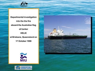
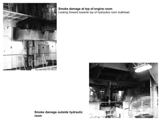
On October 17, 1998, a fire broke out aboard the Australian oil tanker Helix while discharging cargo at a terminal in Brisbane, Queensland. The fire originated in the ship's hydraulic machinery space, where hydraulic pumps powered the cargo and ballast pumps. Three crew members in the engine room at the time felt and heard an explosion and saw a fireball, escaping through the steering flat and an enclosed escape. Smoke quickly filled the accommodation stairwell and engine room. The cargo pumps automatically shut down and crew closed cargo valves. After the crew mustered, two entered the engine room in breathing apparatus and extinguished isolated fires in lagging and a hydraulic pump sump. The fire was contained and ship declared safe by responding firefighters within
The document summarizes the recovery of an EP-3 aircraft in China following an incident in 2001. A Russian AN-124 aircraft was used to transport sections of the disassembled EP-3 from a naval airbase in China to bases in the US. Over several flights, Lockheed Martin personnel carefully dismantled and loaded the aircraft onto the AN-124 under monitoring by the Chinese military, dealing with heat and logistical challenges. Their recovery efforts were successful, with the fuselage ultimately delivered to Dobbins Air Reserve Base in Georgia.
The document summarizes the logistics and operations of recovering an EP-3 aircraft at Lingshui Air Base in China using an AN-124 aircraft over several flights between June and July 2001. The AN-124 flights transported salvaged parts and sections of the disassembled EP-3 out of China. Strict controls were put in place on cargo weights and fuel to avoid further damaging the airfield not designed for large aircraft. Lockheed Martin led the recovery efforts and had medical and evacuation plans in place given the hot working conditions. The Chinese military closely monitored operations and had many rules in place.
The Centennial of Naval Aviation Heritage Paint Project aims to create living history and public awareness of the Navy's heritage by painting active duty aircraft in historic paint schemes from different eras. Originally targeting 18 aircraft, the project grew to include 28 aircraft from both fleet and training command units. The aircraft represent various types and eras from 1914 to 1950, and underwent painting at various maintenance facilities as part of scheduled overhauls while minimizing additional costs. The project helps appreciate Naval Aviation history while the aircraft continue operational missions.
This document discusses MARPOL Annex VI and emissions control from ships. It provides information on key regulations including the ratification process for Annex VI, regulated emissions from ships, and regulations on ozone depleting substances, nitrogen oxides, sulfur oxides, and reception facilities for ship emissions. It also summarizes certification and compliance requirements for ships and engines.
Hugh D. Curran has over 50 years of experience in marine engineering, having served as chief engineer on numerous commercial and government vessels. He currently teaches marine engineering subjects and helps certify personnel. Curran holds numerous licenses and certifications in engineering and has extensive leadership experience from his military career in the US Navy and Air Force.
The document summarizes fuel operations at several Department of Defense fuel terminals and facilities in the Norfolk, Virginia region. It details fuel storage capacities and throughput at Craney Island, Sewells Point, and Yorktown terminals. It also provides an overview of retail fueling facilities at Chambers Field and Naval Amphibious Base Little Creek.
ELT progam at PetroChina Halfaya oilfield, Iraq 2018Edumax Solutions
I designed and managed an ELT program at PetroChina's Halfaya oilfield. We had 150 Iraqi graduate engineers who took part wit trainers from Iraq, Britain, and Egypt. These slides highlight my work at the Training centre and my stay at the base camp.
Transcript of CVR tape in Colgan Air Q400 crashKieran Daly
The transcript summarizes 58 minutes and 32 seconds of cockpit voice recorder audio from Colgan Air flight 3407, which crashed on approach to Buffalo Niagara International Airport on February 12, 2009. It includes discussions between the pilots and air traffic control communications during the takeoff from Newark, climb to cruise altitude, and descent and approach into Buffalo. The recording captured excellent quality audio and ended as the aircraft crashed during the accident sequence.
The STCW establishes standards for watchkeeping on ships. It requires the chief engineer to assign watchkeeping duties and establish standards. It aims to improve training requirements and make countries accountable for enforcing training standards. Countries must provide information to IMO about their training programs and are subject to quality assurance requirements to ensure the proper implementation of the Convention.
This document discusses marine diesel engine exhaust gas emissions and control technologies. It provides background on the types of emissions from diesel engines including NOx, SOx, and particulate matter. The document then examines regulations for emissions including Tier I, II, and III NOx limits as well as sulfur content limits for fuel. It discusses various technologies that can be used to reduce NOx and SOx emissions such as water injection, selective catalytic reduction, and scrubbers.
The document summarizes the logistics and operations of recovering an EP-3 aircraft at Lingshui Air Base in China using an AN-124 aircraft over several flights between June and July 2001. The AN-124 flights transported salvaged parts and sections of the disassembled EP-3 out of China. Strict controls were put in place on cargo weights and fuel to prevent further damage to the airfield from the large AN-124 aircraft. US recovery teams faced challenging work conditions but completed the recovery without injuries. Chinese military personnel closely monitored the operations.
This document summarizes key aspects of MARPOL, the International Convention for the Prevention of Pollution from Ships. It outlines the objectives of MARPOL to minimize pollution from ships, including dumping, oil, and exhaust. It describes the six annexes which regulate pollution from oil, noxious liquids, packaged harmful substances, sewage, garbage, and air emissions. It provides details on regulations within each annex regarding discharge standards, requirements for equipment like oil filtering and monitoring systems, record keeping, and certification requirements. Specifics are given for oil tanker requirements and limitations on discharges within special areas. The document is an extensive overview of MARPOL regulations.
1) The document outlines regulations regarding work and rest hours for seafarers including minimum hours of rest, record keeping responsibilities, exceptions, and annual leave entitlements.
2) It also discusses safe manning requirements for ships, outlining various factors that must be considered to determine an appropriate complement, and notes a safe manning certificate is issued by the MCA.
3) Record keeping responsibilities and requirements for official log books are also covered.
This document discusses ship operations that can cause marine pollution and safety measures to prevent pollution. It identifies bunkering, fuel transferring, bilge water discharge, and tanker operations as key pollution sources. For each, it outlines hazards and recommends procedures like checking equipment, communicating plans, monitoring levels, and following loading/unloading safety protocols. The goal is to reduce risks of accidental oil or chemical releases into the ocean from ship activities and cargo handling.
This document discusses safety procedures for preventing marine pollution from ship operations, specifically tanker operations. It identifies ship operations that can generate pollution such as bunkering, transferring fuel, bilge water discharge, and tanker cargo operations. Standard safety measures are outlined for bunkering, fuel transferring, and tanker loading/unloading to minimize the risk of accidental oil spills. Proper communication, equipment checks, and gradual loading rates are emphasized to avoid static buildup and ensure leaks are quickly detected.
This document discusses the design of ports and harbors for transporting liquefied natural gas (LNG). It defines different types of harbors, including natural, semi-natural, and artificial harbors. It also discusses components of port design like navigation channels, harbor basins, and berthing layouts. The document focuses on berthing structure types for LNG facilities, including deck on pile, sheet pile, diaphragm wall, and caisson designs. It also provides details on LNG characteristics, gas carriers, and different types of gas carrier designs.
IndexTank is a great search indexing service, this gem tries to make that any orm stays in sync with IndexTank easily. It has a simple yet powerful approach to integrate IndexTank with any ORM
This document provides an overview of oil tankers, including their structures, ballast systems, inert gas systems, cargo handling procedures, safety precautions, and emergency response plans. It discusses topics such as segregated ballast tanks, oil discharge monitoring, enclosed space entry permits, pump room entry procedures, tank washing, and emergency procedures. The key purpose of procedures and safety systems on oil tankers is to prevent fires and explosions during cargo operations.
The document summarizes different types of tankers used to transport liquid cargo. It begins by explaining that modern ships specialize in specific cargo types. Tankers are defined as ships designed to carry liquid cargo in bulk. The world's first true tanker, the Gluckauf, was built in 1886 with separate tanks for oil cargo. Tankers are further specialized to carry different liquid cargoes like petroleum, chemicals, liquefied natural gas, liquefied petroleum gas, and even fruit juice and wine. The document then focuses on describing various types of oil tankers classified by cargo capacity like ULCC, VLCC, Suezmax, and Aframax. Safety regulations now require double hulled tank
This document discusses different types of tanker vessels including oil tankers, chemical tankers, and liquefied natural gas carriers. It provides details about the Knock Nevis, the largest tanker ever built at 458 meters long, and the Carlos Fischer, the world's largest tanker for transporting citrus juice bulk at 194 meters long. Technical specifications are given for both vessels.
This document summarizes different types and sizes of oil tankers. It describes how crude tankers transport unrefined crude oil and product tankers transport refined products. It outlines the history of oil tankers from the 1850s transporting oil in barrels to the development of modern tankers in the late 1800s. It discusses the era of supertankers in the 1970s that were over 400 meters long and could carry 500,000 tons. The document concludes by categorizing tanker sizes from Panamax and Handysize up to Ultra Large Crude Carriers and Very Large Crude Carriers that can carry over 200,000 tons.
The document discusses cargo tank venting and inert gas systems on board ships. It introduces the inert gas system and explains how it works to suppress flammability through increasing the oxygen content. It describes the key components of inert gas systems including scrubbers, fans, deck water seals, and instrumentation. It also covers inert gas production methods, system layouts, and applications to shipboard operations like cargo handling and tank washing.
Oil and Liquefied Gas Tanker Operations is a comprehensive separately bookable course designed to provide participants with a technical perspective of shipping operations. The 4 day course will cover technical designs and features of tankers, operational execution based on charterparty terms, port, cargo and ballasting operations, tank cleaning, safety assessment and procedures, all broken down and discussed in detail. In addition, tanker owners, managers, operators and charterers will learn how to best minimize any operational claims and disputes due to accidents either out at sea or berthing at ports.
Fire Protection, Fire Detection & Fire Extinguishing and SOLAS Requirements by Mohd. Hanif Dewan, Senior Engg. Lecturer, International Maritime Academy, Bangladesh.
This document summarizes a presentation on inert gas extinguishing systems. It discusses the requirements for clean agents used in fire protection of electronics areas. It describes inert gases and halocarbon agents as the two categories of clean agents according to NFPA standards. Inert gases are preferred over halocarbon agents for their safety for humans and lack of toxic byproducts. The document outlines the operating principle of inert gas systems, which extinguish fires by diluting oxygen concentration below the level needed for combustion. It also discusses factors to consider in the design of inert gas systems, such as achieving the minimum design concentration. Overall, the presentation concludes that inert gas systems are better than halocarbon systems for fire protection due to their availability, ease of ref
This document discusses a study analyzing accident reports related to engine room fires on ships. The study found that accident reports were lacking important human and organizational factor data, with many reports missing information about supervision, decision-making, crew interaction, and equipment conditions. Interviews with ship engine staff also revealed gaps in reporting minor disturbances and issues. The lack of data on human and organizational causes makes it difficult to fully understand accidents and improve safety.
The document contains technical drawings and assembly instructions for building a model oil tanker out of PVC pipes and wood. It includes individual drawings for parts like the base, wheels, axles, and tanker body, labeled with dimensions and scales. An assembly drawing brings all the parts together and a parts list identifies each component needed to construct the full model.
The document summarizes new regulations under MARPOL Annex V that will prohibit the disposal of ship-generated garbage at sea beginning January 1, 2013. Shipboard garbage will need to be segregated and sent to port waste reception facilities for disposal. Certain cleaning agents may still be discharged if non-harmful. Discharge criteria and restrictions vary depending on whether the ship is outside or within a MARPOL special area, which include regions like the Mediterranean, Baltic, and Wider Caribbean seas.
Aarush Fire Systems is one of the fastest growing companies in Fire Fighting industry. We offer to the industry a complete selection of products & services to provide turnkey & one stop solution for all kinds of fires. We provide all types of Fire Extinguishers & Spares, Hydrant system & its components, Sprinkler system & its components, Fire alarm & Smoke detection systems and its components, Co2 flooding systems & its components, Fire doors, Safety doors. We also provide class room training as well as live demonstrations of fire fighting equipments & systems. We have tie ups with several organizations & associates to provide the best & most advanced products available in the country today and we are serving in this industry from last 7 years, started with sister concern firm.
This document provides information about an upcoming LNG Tanker Operations training course. The course will take place on May 19-20, 2014 at the Grand Copthorne Waterfront Hotel in Singapore. It will provide attendees with knowledge on LNG tanker operations, commercial arrangements, cargo handling procedures, safety practices, and regulations. Attendees can save up to 40% by registering a group of 3 or more delegates for the special group rate. [END SUMMARY]
The document discusses marine coatings and protective coatings. It describes their main function is to protect steel structures from corrosion and chemicals. Some key applications mentioned include marine vessels, offshore oil rigs, industrial structures, and transportation vehicles. It provides statistics on worldwide consumption of anticorrosion coatings. It also describes the role of various coatings in protecting different parts of ships from corrosion. Some key requirements for coatings are also listed such as resistance to corrosion and chemicals. The document discusses the composition, properties and uses of paints as well as methods for surface preparation and coating application.
This document provides an overview of gas detection and analysis solutions from a1-cbiss. It summarizes their portfolio including portable gas detectors, fixed gas monitoring systems, gas detection tubes, and more. It also outlines their services including consultancy, installation, commissioning, and ongoing support. The document highlights their expertise in key markets such as oil and gas, petrochemical, and other industries where gas detection is important for safety.
The document provides an overview of the sinking of the Titanic and lessons that were learned. It discusses how the Titanic was considered unsinkable due to its design with watertight compartments. It received several iceberg warnings via wireless messages that were not properly communicated to the bridge. Regulations at the time regarding lifeboat capacity were outdated, resulting in not enough lifeboats for all passengers and crew. As a result of investigations after the sinking, new international safety regulations were introduced.
The document provides information about preparing for the IELTS reading test. It discusses key details about the test, including that it takes one hour to complete three passages of 500-900 words each with 40-50 questions. Most students feel there isn't enough time, so practice tests are important to develop speed-reading skills. The document then provides sample questions to practice common question types in the test and a sample reading passage to use for the examples and questions.
The document summarizes two major nuclear power plant disasters - Chernobyl in 1986 and Three Mile Island in 1979. It describes the causes of the accidents, their impacts, and lessons learned. The Chernobyl accident was caused by flawed reactor design and human error, resulting in a massive uncontrolled radioactive release. It directly caused 28 deaths and long term health impacts. Three Mile Island's partial core meltdown released some radiation but no direct health effects. It highlighted operational and communication issues. Both led to improved global nuclear safety standards and cooperation.
The 2010 eruption of the Eyjafjallajökull volcano in Iceland grounded flights across Europe for several weeks, stranding millions of travelers. While volcanic ash poses a serious hazard to aircraft engines, the response to this eruption revealed issues with Europe's preparedness and coordination for such an event. Specifically, the safe ash concentration levels that triggered flight bans were established without scientific basis. Additionally, individual country responses were not well integrated across Europe. Future eruptions, especially of larger volcanoes, could cause significantly longer disruptions, highlighting the need for improved volcanic risk assessment and cross-border emergency planning in Europe.
The Carnival Splendor experienced a fire in the aft engine room on November 8, 2010 which resulted in a total loss of power. The fire was caused by a mechanical failure in one of the diesel generators which ejected flammable materials and ignited other nearby combustibles. It took crews two hours to locate the relatively small fire in electrical cable runs due to smoke, and attempts to extinguish it with handheld extinguishers were unsuccessful. The fixed CO2 fire suppression system also failed to activate, contributing to the ineffectiveness of firefighting efforts. The lack of backup power led to a multi-day tow back to port for repairs. The incident report includes recommendations to improve fire safety systems and crew training and procedures
The Costa Concordia cruise ship struck rocks near the coast of Italy on January 13, 2012. The ship was sailing too close to shore in an apparent maneuver by the captain. It collided with rocks which caused flooding in several compartments, resulting in a blackout. The ship quickly took on a list and was evacuated as it sank further into the water. Over 30 lives were lost in the accident and evacuation. An investigation is underway to determine the causes of the incident.
- On November 25, 1998, a fire at an Equilon Enterprises oil refinery delayed coking unit killed six people after a power outage caused abnormal process conditions in one of the coke drums.
- After the power was restored, operators attempted to empty the partially filled coke drum. They decided to open the vessel after injecting some steam based on the outside of the drum appearing cool to the touch. However, the core contents were still hot, causing flammable vapors to ignite upon opening and kill six people.
- The incident showed the need for management of change policies to cover abnormal situations and deviations from standard operating procedures to systematically review risks introduced by non-routine operations.
I. Background about Piper Alpha
II. General Purpose of the platform operation
III. The happening Event Timeline
IV. Cause and Effect of the disaster
V. Key Failures
VI. Improvement and prevention
VII. Conclusion
On July 6, 1988, an explosion destroyed the Piper Alpha oil platform in the North Sea, killing 167 workers. Piper Alpha was a large fixed platform that produced oil and gas from 24 wells. A series of explosions were caused by failures in the condensate pumps and gas lines. As a result of the disaster, the Cullen Inquiry was established and new safety regulations were implemented for operating in the North Sea, focusing on equipment procedures, personnel training, platform design, and emergency response.
This document provides details about shipboard routine and safety procedures on the Crowley tanker Florida. It describes the ship's engine room layout and machinery. The engineering crew consists of 6 members including the chief engineer. Watch duties involve taking rounds every 6 hours to monitor equipment. Safety procedures are strictly followed, including lock-out/tag-out when working on machinery, confined space entry protocols, chemical storage regulations, and inert gas system operation to reduce oxygen levels when discharging cargo.
The document summarizes two major oil spills - the Amoco Cadiz spill of 1978 and the BP Deepwater Horizon spill of 2010 - and the response efforts to each. The Amoco Cadiz spill released over 220,000 tons of oil off the coast of France, polluting 300km of coastline. Cleanup efforts were hampered by weather. The BP spill released an estimated 4.2 million barrels into the Gulf of Mexico over 87 days. Initial response efforts to both spills employed vessels, booms, and dispersants to contain and remove spilled oil, while lessons highlighted the need for improved safety standards and ethical crisis response.
Flight 236 from Toronto to Lisbon lost all engine power over the Atlantic Ocean due to a fuel leak caused by improper maintenance. The pilots, Captain Robert Piché and First Officer Dirk de Jager, glided the plane for over 100 km and landed safely in the Azores, saving all 306 people on board. An investigation found that a wrongly installed part during maintenance caused a fuel line to rupture. While pilot error was also cited, the pilots were hailed as heroes for their emergency landing without power.
The Korean Air Cargo Flight 8509 crashed near Great Hallingbury, UK shortly after takeoff from London Stansted Airport on December 22, 1999, killing all 4 crew members. An investigation found that one of the aircraft's Inertial Navigation Units had failed, providing incorrect roll data to the captain's attitude indicator. During climbout after takeoff, the comparator warning sounded multiple times due to differences between the captain and first officer's indicators, but the pilots did not respond appropriately despite prompts from the flight engineer. The aircraft entered a steep and uncommanded left bank, crashing 55 seconds after takeoff. Contributing factors included a misdirected repair attempt of the attitude indicator that did not resolve the underlying issue, as well
This document provides an overview of natural gas liquefaction processes for a university semester project on simulating the C3MR natural gas liquefaction process. It begins with an introduction to liquefied natural gas and its advantages over vapor natural gas. It then discusses the history of LNG and summarizes several common industrial liquefaction processes, including cascade processes, mixed refrigerant processes, and specific processes like the C3MR, SMR, DMR, Linde and AP-X processes. The document also reviews gas purification processes and provides an outline for the modeling section of the semester project.
The Refugio oil spill occurred in May 2015 when an onshore pipeline ruptured near Santa Barbara, California, releasing over 100,000 gallons of crude oil. A series of interactions between the pipeline and pump stations led to increased pressure in the line that caused it to burst at its weakest, corroded point. While the direct cause was pipeline corrosion, the spill was the result of multiple system failures, including issues at nearby pump stations that impacted pipeline pressure. The timeline of events is described, highlighting delays in reporting the spill and issues with pipeline inspection reliability. The spill impacted coastal and marine environments for over a month.
The Application of Unmanned Marine Vehicles to Maritime Search and RescueVR Marine Technologies
This presentation was delivered at the SURV9 – Surveillance, Search and Rescue Craft Conference, 18th April 2018 in London, UK. It looks at the application of UMVs to search and rescue, covering:
1. Technology;
2. Safety of SAR personnel;
3. Improving rescue response;
4. How Unmanned Marine Vehicles can help;
5. Cost benefit analysis;
6. Challenges;
7. the way forward.
This document provides information about harbours and facilities provided at harbours. It discusses the key roles of harbours as the interface between inland and marine transportation. It describes common facilities like wharfs, jetties, warehouses, and equipment provided. It also discusses common cargoes handled at ports and standard firefighting arrangements. Specifically, it outlines firefighting pumps, equipment, and international standards like SOLAS that ports must follow.
How are Lilac French Bulldogs Beauty Charming the World and Capturing Hearts....Lacey Max
“After being the most listed dog breed in the United States for 31
years in a row, the Labrador Retriever has dropped to second place
in the American Kennel Club's annual survey of the country's most
popular canines. The French Bulldog is the new top dog in the
United States as of 2022. The stylish puppy has ascended the
rankings in rapid time despite having health concerns and limited
color choices.”
The Steadfast and Reliable Bull: Taurus Zodiac Signmy Pandit
Explore the steadfast and reliable nature of the Taurus Zodiac Sign. Discover the personality traits, key dates, and horoscope insights that define the determined and practical Taurus, and learn how their grounded nature makes them the anchor of the zodiac.
Best Competitive Marble Pricing in Dubai - ☎ 9928909666Stone Art Hub
Stone Art Hub offers the best competitive Marble Pricing in Dubai, ensuring affordability without compromising quality. With a wide range of exquisite marble options to choose from, you can enhance your spaces with elegance and sophistication. For inquiries or orders, contact us at ☎ 9928909666. Experience luxury at unbeatable prices.
Call8328958814 satta matka Kalyan result satta guessing➑➌➋➑➒➎➑➑➊➍
Satta Matka Kalyan Main Mumbai Fastest Results
Satta Matka ❋ Sattamatka ❋ New Mumbai Ratan Satta Matka ❋ Fast Matka ❋ Milan Market ❋ Kalyan Matka Results ❋ Satta Game ❋ Matka Game ❋ Satta Matka ❋ Kalyan Satta Matka ❋ Mumbai Main ❋ Online Matka Results ❋ Satta Matka Tips ❋ Milan Chart ❋ Satta Matka Boss❋ New Star Day ❋ Satta King ❋ Live Satta Matka Results ❋ Satta Matka Company ❋ Indian Matka ❋ Satta Matka 143❋ Kalyan Night Matka..
Satta matka fixx jodi panna all market dpboss matka guessing fixx panna jodi kalyan and all market game liss cover now 420 matka office mumbai maharashtra india fixx jodi panna
Call me 9040963354
WhatsApp 9040963354
SATTA MATKA DPBOSS KALYAN MATKA RESULTS KALYAN CHART KALYAN MATKA MATKA RESULT KALYAN MATKA TIPS SATTA MATKA MATKA COM MATKA PANA JODI TODAY BATTA SATKA MATKA PATTI JODI NUMBER MATKA RESULTS MATKA CHART MATKA JODI SATTA COM INDIA SATTA MATKA MATKA TIPS MATKA WAPKA ALL MATKA RESULT LIVE ONLINE MATKA RESULT KALYAN MATKA RESULT DPBOSS MATKA 143 MAIN MATKA KALYAN MATKA RESULTS KALYAN CHART
Profiles of Iconic Fashion Personalities.pdfTTop Threads
The fashion industry is dynamic and ever-changing, continuously sculpted by trailblazing visionaries who challenge norms and redefine beauty. This document delves into the profiles of some of the most iconic fashion personalities whose impact has left a lasting impression on the industry. From timeless designers to modern-day influencers, each individual has uniquely woven their thread into the rich fabric of fashion history, contributing to its ongoing evolution.
Discover timeless style with the 2022 Vintage Roman Numerals Men's Ring. Crafted from premium stainless steel, this 6mm wide ring embodies elegance and durability. Perfect as a gift, it seamlessly blends classic Roman numeral detailing with modern sophistication, making it an ideal accessory for any occasion.
https://rb.gy/usj1a2
The APCO Geopolitical Radar - Q3 2024 The Global Operating Environment for Bu...APCO
The Radar reflects input from APCO’s teams located around the world. It distils a host of interconnected events and trends into insights to inform operational and strategic decisions. Issues covered in this edition include:
Part 2 Deep Dive: Navigating the 2024 Slowdownjeffkluth1
Introduction
The global retail industry has weathered numerous storms, with the financial crisis of 2008 serving as a poignant reminder of the sector's resilience and adaptability. However, as we navigate the complex landscape of 2024, retailers face a unique set of challenges that demand innovative strategies and a fundamental shift in mindset. This white paper contrasts the impact of the 2008 recession on the retail sector with the current headwinds retailers are grappling with, while offering a comprehensive roadmap for success in this new paradigm.
Ellen Burstyn: From Detroit Dreamer to Hollywood Legend | CIO Women MagazineCIOWomenMagazine
In this article, we will dive into the extraordinary life of Ellen Burstyn, where the curtains rise on a story that's far more attractive than any script.
Zodiac Signs and Food Preferences_ What Your Sign Says About Your Tastemy Pandit
Know what your zodiac sign says about your taste in food! Explore how the 12 zodiac signs influence your culinary preferences with insights from MyPandit. Dive into astrology and flavors!
The Most Inspiring Entrepreneurs to Follow in 2024.pdfthesiliconleaders
In a world where the potential of youth innovation remains vastly untouched, there emerges a guiding light in the form of Norm Goldstein, the Founder and CEO of EduNetwork Partners. His dedication to this cause has earned him recognition as a Congressional Leadership Award recipient.
𝐔𝐧𝐯𝐞𝐢𝐥 𝐭𝐡𝐞 𝐅𝐮𝐭𝐮𝐫𝐞 𝐨𝐟 𝐄𝐧𝐞𝐫𝐠𝐲 𝐄𝐟𝐟𝐢𝐜𝐢𝐞𝐧𝐜𝐲 𝐰𝐢𝐭𝐡 𝐍𝐄𝐖𝐍𝐓𝐈𝐃𝐄’𝐬 𝐋𝐚𝐭𝐞𝐬𝐭 𝐎𝐟𝐟𝐞𝐫𝐢𝐧𝐠𝐬
Explore the details in our newly released product manual, which showcases NEWNTIDE's advanced heat pump technologies. Delve into our energy-efficient and eco-friendly solutions tailored for diverse global markets.
❼❷⓿❺❻❷❽❷❼❽ Dpboss Matka Result Satta Matka Guessing Satta Fix jodi Kalyan Final ank Satta Matka Dpbos Final ank Satta Matta Matka 143 Kalyan Matka Guessing Final Matka Final ank Today Matka 420 Satta Batta Satta 143 Kalyan Chart Main Bazar Chart vip Matka Guessing Dpboss 143 Guessing Kalyan night
❼❷⓿❺❻❷❽❷❼❽ Dpboss Matka Result Satta Matka Guessing Satta Fix jodi Kalyan Fin...
Oil Tanker
1. Departmental investigation
into the the fire
aboard the Australian flag
oil tanker
HELIX
at Brisbane, Queensland on
17 October 1998
2. Navigation Act 1912 Navigation (Marine Casualty) Regulations
investigation into the the fire aboard the Australian flag oil tanker
HELIX
at Brisbane, Queensland on 17 October 1998
Contents Published: June 1999
ISBN 0 642 20021 1
Sources of information The Investigation into marine casualties occurring within the Commonwealth's
jurisdiction are conducted under the provisions of the Navigation (Marine
Casualty) Regulations, made pursuant to sub section 425 (1) (ea) and 425 1 (AAA)
Summary of the Navigation Act 1912. The Regulations provide discretionary powers to the
Inspector to investigate incidents as defined by the regulations. Where an
investigation is undertaken the Inspector must submit a report to the Secretary of
Narrative the Department. It is Departmental policy to publish such reports in full as an
educational tool.
Comment and analysis To increase the value of the safety material presented in this report readers are
encouraged to copy or reprint the material, in part or in whole, for further
distribution, but should acknowledge the source.
Conclusions
For further information please contact:
Submissions Inspector of Marine Accidents
Marine Incident Investigation Unit
P O Box 594 CANBERRA ACT 2601
Details of Helix AUSTRALIA
Phone: +61 2 6274 7324
Attachment
Fax: +61 2 6274 6699
Email: miiu@miiu.gov.au
MIIU on the INTERNET
Information relating to this report and other marine investigation reports can be
located from the Marine Incident Investigation Unit's Internet homepage at our
URL: http://www.miiu.gov.au
3. Sources of information
The Master, officers and crew of Helix
ASP Ship Management
Frank Mohn A/S
Bureau of Air Safety Investigation, Metallurgy Laboratory
Queensland Fire and Rescue Authority
Shell Australia Ltd.
4. Summary
In the morning of 17 October 1998, the Australian tanker Helix was discharging oil products at the Shell
terminal at Pinkenba, on the Brisbane River.
At 0800, three of the ship’s crew were in the engine room, starting a daily routine of maintenance. In the
cargo control room the Mate was handing over the cargo watch to the 3rd Mate. Shortly after 0800, a fire
broke out in the machinery space housing the motors and pumps for the hydraulic power units. A fireball
travelled through the ventilation grating where the exhaust trunks penetrated the bulkhead to the main
machinery space.
The three personnel in the engine room made their escape, two by way of the door to the steering flat and
one by way of the encased escape from the bottom plates of the main machinery space. In the cargo
control room, personnel heard a thump and felt a sensation through the deck. Almost simultaneously
smoke filled the internal stairwell to the main deck and rolled along the deckhead.
The cargo pumps closed down automatically and the Mate directed crew on deck to close the cargo
manifold valves. The fire alarm was sounded and the shore supervisor called the Queensland Fire and
Rescue Authority at 0804.
The crew mustered at their fire stations. The ventilation fans and motors were stopped and all remote fuel
stops were closed. The smoke cleared very rapidly and the Chief Engineer entered the engine room and
laid out a fire hose to the hydraulic machinery space, within which there appeared to be a fire still burning.
Two crew, dressed in breathing apparatus, made an entry to the main machinery space from the main deck
level. They reached the machinery control room level and then descended to the hydraulic room level.
They could see an isolated piece of lagging burning outside the ventilation grille, which was extinguished
using a portable extinguisher. On entering the hydraulic machinery space they found a small fire burning in
one corner of the “save-all” beneath the hydraulic pump units. This too was extinguished.
The remainder of the lower levels of the engine room were checked and no fire was found. Five units and a
command vehicle of the Queensland Fire and Rescue Authority arrived at 0816 and fire officers boarded
5. the ship. At 0839 the ship was declared safe.
Damage was limited to destroyed light fittings, melted indicator and warning lights and smoke damage.
Little damage was sustained to the ship’s electrical cabling.
Initial examination indicated that two bolts, securing the hydraulic oil damper/ filter unit to No.3 hydraulic
pump had failed, allowing a spray of fuel to come into contact with a source of ignition, most likely the
exhaust trunking of the diesel engine driving No.3 hydraulic pump.
6. Fire damage immediately aft of hydraulic room bulkhead
Small lagging fire occured on this pipework
Smoke damage around diesel exhaust trunks above
hydraulic room
7. Narrative
The Australian flag tanker Helix is owned by Phinda Pty Ltd, managed by ASP Ship Management and is on
charter to the Shell Company of Australia. Built in 1997 the ship entered service in August 1997. It is
nearly 183 m in length overall, and its deadweight is 46,092 tonnes at a summer draught of 12.518 m. It is
powered by a
6-cylinder Sulzer RTA diesel engine of 8,840 kW driving a single shaft and has a service speed of 14.5
knots.
Helix has a crew of 18, a master and three mates, four engineers, seven integrated ratings (IR) and three
catering staff. The main machinery space is classed as an “unmanned machinery space” (UMS) and the
engineer officers maintain a daywork system with one engineer on call in the “silent hours”. The deck
officers maintain a three watch system both at sea and in port when loading or discharging. The integrated
ratings work a rotating roster, which includes watchkeeping and daywork, with deck and engine room
duties.
The accommodation block and main machinery space is aft of frame 47. The accommodation block is
arranged in six deck levels with the cargo control room on level one, crew accommodation on levels two,
three and four and the bridge on level 5. The galley and messes are arranged on the main deck level.
Below the main deck, the main machinery space (frames 15 to 47) is divided into four general levels above
the tanktops - the lower plates, platform 1, platform 2 and the tween deck.
Helix is a double-hulled tanker designed to carry petroleum products. The cargo tanks, all forward of frame
47, are numbered one to ten and are divided by a central longitudinal bulkhead giving 20 cargo tanks in all.
In addition there are two slop tanks which can also be used as parcel tanks. All the cargo and slop tanks
are protected by inert gas. The space between the side shell plating and the cargo tanks and the double
bottom spaces under the cargo tanks are divided into ballast tanks.
The ship is fitted with a Framo hydraulic cargo pumping system. Each cargo and ballast tank has an
independent, hydraulically powered, deepwell pump. A central hydraulic system, manufactured by Frank
Mohn A/S of Nesttun, Norway, supplies power to the 24 cargo and ballast pumps. The hose handling crane
8. and the bow thruster propeller are also powered by this central system.
System hydraulic pressure is provided by five hydraulic pumps located in the hydraulics room. The
hydraulics room is at the forward end of the engine room at the second platform level, between frames 41
and 47. Two pumps are electrically driven and three are driven by dedicated diesel engines; all pumps
feed a common manifold. There is a screen between the diesel engines or electric motors and their
respective hydraulic pumps. The exhaust trunks are well lagged and, from the diesel engines, lead over the
top of the screen and penetrate the bulkhead into the main machinery space at the deckhead level through
a grille to the engine room. Beneath the hydraulic motors a “save-all” is constructed to retain any leaking
oil. The space is illuminated by fluorescent light fittings with tubes protected by polycarbonate covers.
The Fire
Helix berthed starboard side to the Pinkenba oil berth at about 2000 on 16 October 1998 with eleven
grades of oil product. Discharge of cargo started with four grades of product being discharged
simultaneously, requiring all five hydraulic pumps.
During the evening a problem arose with No.2 port deepwell pump and the Chief Engineer and others were
engaged in rigging a spare portable pump until about 0030 on 17 October. Cargo discharge continued
throughout the night. Minor operational problems activated UMS alarms and the duty engineer attended to
each problem.
Just before 0800 on 17 October, the 1st Engineer entered the main machinery space and went to the control
room on the port side at the tween deck level. One of the IRs was already in the main machinery space
setting up an impact wrench ready to work on the platform around the engine. A second IR entered the
control room and picked up the checklist ready to take the various temperature and other readings for the
engine log book. The second IR exited by the forward control room door. At the same time the 1st Engineer
remembered that he had left his daily work sheet in the office next to the cargo control room and left the
control room by the after door and started up the port ladder to the main deck level.
The 1st Engineer was about half way up the ladder when he heard a sound of some sort of explosion
9. described as a “whumph”. He looked over the rail and saw a large orange fireball at his level coming
towards him. His immediate reaction was to go up the ladder, but after just one step he turned and went
down to the tween deck level as fast as he could. The IR making rounds was about half way down the
ladder between the tween deck and platform 2 facing aft when he heard a blast, which he described as
rather like a large oxy-acetylene torch being lit. He looked around and saw a cloud of orange flame which
seemed to be getting bigger and bigger. He could feel radiant heat and smell the hot smoke. Above him
he could see the 1st Engineer making for the entrance to the steering flat and followed him. Both men
escaped through the steering flat and then by ladder to the open poop deck. By this time other ship’s
personnel were beginning to muster at the fire stations on the poop deck.
The IR, engaged in rigging the air hose and scaling machine, estimated he had been in the engine room a
matter of 3 or 4 minutes when he smelt smoke, an unusual smell that should not have been there. Within
seconds he heard a “whoosh”. The air seemed to explode upwards two levels above where he was
standing and he saw a big fire mushroom funnelling up and debris started to fall around him. He knew he
could not go upwards within the main machinery space, so went down to the bottom plates and escaped
through the vertical escape trunking to the main deck accommodation. As he climbed out of the trunking
near the mess room he heard the fire alarms sounding and he told the people there to go to their
emergency stations. He then reported to his fire station on the poop.
At 0800, the Chief Engineer was at the after end of the main deck preparing to take a consignment of bulk
lubricating oil from a road tanker. A few minutes after 0800 he realised that the cargo pumps were slowing
and stopping and everything had gone quiet. At the same time he saw smoke coming from the foam room
bulkhead vent on the starboard side of the accommodation block at main deck level. He immediately went
to the fire station on the starboard side of the poop deck and, as he did so, he heard the fire alarms.
At 0800 the Mate was handing over to the 3rd Mate who was relatively new to the ship. Four products were
being pumped. In 9 P and S tanks there was about one hour to go before the tanks were empty and the
Mate suggested that the 3rd Mate reduce the speed of the pump to prevent overspeed or cavitation. As the
3rd Mate adjusted the speed they heard a “thump”, as though water-hammer had occurred in pipe work in
the accommodation. The alarm indicating “low return line pressure” on the hydraulic system console
10. sounded and all hydraulic pumps and motors stopped automatically.
Both officers became aware of smoke along the deckhead and, outside the control room, thick smoke was
coming from the internal stairwell to the main deck. They immediately moved to the external starboard
door to the open deck as the fire alarms were sounding. The Mate instructed the watch on deck to close
the manifold valve and to isolate the inert gas system. The jetty supervisor was close to the ship and the
lubricating oil tanker. He called up to those at the manifold asking if “everything was all right.” The IR
closing the valves could see smoke coming from the accommodation and he called to the supervisor to call
the shore fire brigade.
At about 0800, the Master was in the ship’s office on the starboard side of level 1 deck. He had just joined
and was in the company of the outgoing master. They noticed the shutting down of the ventilation. Almost
simultaneously they were alerted by the fire alarm and the indication of fire on the alarm repeater panel.
The Master entered the alleyway and noticed a haze of smoke, but on opening the central stairwell he
found heavy smoke. He left the accommodation by the port entrance onto the weather deck to go to the
bridge by the external ladders. On the weather deck the Master met an IR, who informed him that there
was a fire in the Framo (hydraulic) room. On the bridge, he found the port door was locked so returned to
level 4 deck where he re-entered the accommodation and made his way to the bridge via the central
stairwell. The fire alarm panel confirmed a fire in the Framo room and the Master took overall command of
the emergency. Using the bridge VHF, he notified all concerned of the fire’s location.
When the fire alarm sounded the crew mustered at their appointed stations. The Mate and Chief Engineer
arrived at the fire station at almost the same time. The Mate opened the door of the fire control room but
smoke billowed out. They then went to the fire equipment room, a small locker about 2.2 m square at the
starboard after end of the deckhouse. Again when they opened the door smoke billowed out. The Mate
took a deep breath of clean air and entered to find the breathing apparatus (BA) sets, which were hung on a
frame inside the door. He found one but dropped it close to the door. He came out and then went in again
and found a second set. Meanwhile the Chief Engineer had reached inside the locker and found the
dropped set.
By this time the Chief IR, the IR on deck watch and other crew members had arrived. The Mate and the
11. Smoke damage at top of engine room
Looking forward towards top of hydraulics room bulkhead
Smoke damage outside hydraulic
room
12. watch IR dressed in the BA sets. The Mate told the IR not to fit the BA regulator, to save air, until they were
ready to make an entry. The Mate then re-entered the fire equipment locker and brought out the BA control
board and torches.
The smoke was beginning to clear and the 1st Engineer was able to enter the fire station and shut the quick-
closing fuel valves while the 2nd Engineer made for his fire station in the engine control room.
When the fire party were kitted up and making their way to the aft deck, with the intention of making an
entry through the aft end of the engine room, the Chief Engineer checked the atmosphere in the engine
room through the starboard door from the fire station. Lighting was on, although darker than usual due to
smoke-blackened diffusers at the main-deck level. Finding that there was no undue heat and the
atmosphere was almost clear, he entered and made his way towards the hydraulics room; the area to which
the fire appeared to have been confined. As he made his way down the atmosphere cleared completely.
After running out the starboard engine room fire hose to the closed hydraulics room door in preparation for
the arrival of the fire party, the Chief Engineer entered the engine control room to start the emergency fire
pump and to update the 2nd Engineer on events.
The emergency fire pump failed to start and, when he rang the bridge to inform the Master of this problem,
he was told that it had also failed to start when an attempt had been made to start it from the bridge. The
3rd Engineer and an IR were sent to the forecastle to start the pump manually.
When the fire party was ready, the Mate and IR went to the door to the fire control room, fitted the BA
regulators and entered. Their entry was timed on the BA board. On the way through the fire control room
the Mate operated all the ventilation trips. The two men entered the alleyway outside the main machinery
space door. Once there, the IR tested the door with the back of his hand and found that it was not unduly
hot. They opened the door carefully and found that it was possible to make an entry. Inside there was, by
now, little smoke; it was not thick and they were able to see quite well.
The engine room flaps had not been closed and this had had the effect of enabling the smoke to dissipate
as rapidly as it formed.
13. The Mate had realised that the fire was probably related to the failure of the cargo pumps and any fire was
probably in the hydraulics room. The two men descended the two flights of ladders to the hydraulics room
level. Outside the hydraulics room, close to the ventilation grille and below the exhaust trunks from the
diesels, there was a small fire in some lagging on a pipe leading to the hotwell tank. Using a foam
extinguisher they extinguished the fire in the lagging.
They then made an entry into the hydraulics room and found a small fire burning in the inboard after end of
the save-all beneath No.3 hydraulic pump. This fire was also extinguished using the foam extinguisher. No
other fire was obvious.
The Mate went to check the remainder of the engine room. There seemed to be no other area of fire and all
seemed in order. Near the bottom plates he found a hard hat. He reported the state of the main machinery
space to the bridge and the finding of the hard hat, requesting a roll call of the ship’s crew. All the crew
however had already been accounted for. By this time the atmosphere in the engine room was quite clear.
At 0810 the Master received a report that men in BA sets had entered the engine room and, at 0815, a
further report that the fire had been extinguished.
A call for assistance from the fire brigade was put through to harbour control over the VHF. The fire brigade
arrived alongside at 0816. At about 0820, fire officers from the Queensland Fire and Rescue Service
arrived in the engine room. After a thorough inspection of the space, they confirmed the fire was
extinguished.
Although the ship suffered significant damage to polycarbonate light diffusers and various other plastic
fittings around the machinery space, there was minimal other damage, such as to electric wiring. There
was widespread smoke damage. However, the ship was able to resume discharge of its cargo.
15. Comment and analysis
Site of the fire
Examination of the fire scene centred on the hydraulic room at the 2nd platform level at the forward end of
the engine room. The source of fuel for the fire was found to be hydraulic oil from No.3 hydraulic pump
escaping from a joint between the hydraulic pump and the hydraulic oil discharge filter/pulse damper unit.
Two socket-head cap bolts securing the top of the filter had failed allowing hydraulic oil to escape.
Framo hydraulic system
The hydraulic power pack, which supplies pressure to
the Framo central hydraulic system, consists of three
Rexroth A4V 500 and two A4V hydraulic pumps each of
which provides an oil delivery of 824 litres/min. at 258
bar pressure. The pumps and their prime movers are
all mounted on a common “skid” base. Two of the
pumps, Nos.1 & 2, are driven by 405 kW, 60 Hz, 3
phase, electric motors and the remainder, Nos.3 to 5,
are driven by 460 kW Cummins GTA1963 diesel
engines. The pumps are connected by flexible hoses to
the hydraulic supply and return pipework of the ring
main.
On the side of each hydraulic pump, there is attached a
combined filter, bypass and pressure pulse damping
unit. (See photo). The pulse damper is simply a
Hydraulic pumps (No.3 damper/filter unit
volume chamber, 495 mm long and approximately 240
removed)
mm in diameter, secured to the side of the pump by four
20 mm dia., 200 mm long socket head cap bolts at the
16. pump’s free end. Sealing is effected by means of an O-ring. The bolts are made of grade 12.9 high tensile
steel having a tensile strength of 1200 MPa and a set limit stress of 1080 MPa. At the pump’s drive end,
the pulse damper is secured to the pump body by a right-angled pressed steel bracket and two 20 mm dia.
hexagon-head set screws. (See photo top page12).
The oil in use in the hydraulic system is Shell Tellus 46, having a flash point of 267°C, a viscosity of 46 cSt
at 40°C, and a minimum auto-ignition temperature of 320°C.
The failure
At the time of the incident, No.3 hydraulic pump was in use for the cargo discharge. Following the fire, it
was found that the two upper set bolts, securing the pulse damper unit to the HP outlet flange of the
hydraulic pump, had failed approximately 180 mm below the heads of the bolts. The two lower bolts were
found slack. The upper eye in the bracket securing the other end of the pulse damper to the pump body
had failed (see photo bottom page 12 ). The effect of these failures was to allow the pulse damper to move
relative to the body of the hydraulic pump and for the joint to open up to the point where the O-ring had
failed, allowing the escape of hydraulic oil under high pressure.
The supporting bracket, at the pump drive end, for the pulsation damper/filter unit was distorted and
cracked across the bolt holes. Significant marking due to vibration was found on the pump flange where
the bracket was secured.
It was also noticed during the investigation that these brackets on each of the other diesel-driven pumps i.e.
Nos.4 & 5, had cracked in way of the bolt holes where they were connected to the pump body flange. On
pump No.4, the lower 20 mm × 55 mm hexagon head screw securing the bracket had failed. The brackets,
and their securing screws, on the two pumps driven by electric motors remained intact.
The bolt clearance holes in the attachment flange of the pulsation damper, where it joins the pump body,
were found to be worn due to relative movement of the parts. Some fretting marks were evident on the two
mating surfaces and the split O-ring was distorted. The thread in one of the holes in the pump body was
damaged but the depth of the hole was 32 mm allowing sufficient clearance for the end of the bolt; the
18. bolts had not “bottomed”.
Metallurgical examination
The failed bolts were submitted to the metallurgical laboratory of the Bureau of Air Safety Investigation for
examination and the report is attached at Annex A.
The report on the examination stated that the two failed bolts had fractured as the result of fatigue crack
growth. The remaining two (intact) bolts had no obvious indications of crack growth.
It was evident that the fracture of one bolt preceded the fracture of the other. Fatigue in the first bolt which
failed was caused by alternating stresses aligned with the axis of the bolt. The indication of number of
cycles to failure was roughly consistent with the pump running/pump shutdown cycles during cargo
discharges over the life of the ship.
The features of fatigue crack growth in the second bolt were consistent with the application of alternating,
rotating, prying loads under the head of the bolt. This type of fatigue crack growth is consistent with an
increased ability of the damper assembly to move with respect to the pump housing following the fracture of
the first bolt and the bracket which had been supporting the end of the damper at the pump flange.
The fracture of two cap bolts by fatigue indicates that the magnitude of alternating load imposed on the
bolts during the operation of the hydraulic pump exceeded the fatigue endurance stress for the bolts.
The primary defence for fatigue in screws/bolts subjected to alternating stresses during operation is the
establishment of an appropriate preload in the shank of the bolt during assembly. The most common
method of establishing this preload is by applying a specified torque to the bolt head during tightening.
It was notable during the examination of the bearing surfaces of the bolt threads and bolt heads that there
was little evidence of interaction with the mating surfaces in the pump housing and damper assembly. This
lack of surface interaction (scoring, ploughing) indicates a low assembly torque and consequently low bolt
preload.
19. No anomalies were observed in the thread forms of the fractured bolts which may have increased thread
friction, thereby reducing the preload established by the application of the specified torque.
Section 4.10 of the Framo manual for the hydraulic system contains information on the tightening torques
for bolts. At 4.10.3 it states “If no torque is specified in service instruction or on drawing, use tightening
torques according to the following table …”
The table contains tightening torque for a range of thread sizes and for three different qualities of steel. For
M20 threads in 12.9 high tensile steel, the tightening torque specified is 660 Nm, with the threads
lubricated. Another table, however, was found in the service instructions from the supplier of the Rexroth
hydraulic pumps, Breuninghaus Hydraulik. This table indicated that, for M20 bolts in grade 12.9 steel, the
correct tightening torque should have been 590 Nm. This table was also generic, not referring specifically
to the bolts in question.
To further confuse this issue, following the incident, information received by ASP Ship Management from
Frank Mohn A/S, indicated that the correct torque for the tightening of these bolts is 641 Nm. Whichever of
these three figures, 590, 641 or 660 is taken as correct, it would appear that the torque figure to which the
bolts should have been tightened during assembly was in the order of 600 Nm.
Maintenance records on the vessel do not indicate that any work had been carried out on No.3 hydraulic
pump which would have necessitated the dismantling of the joint in question since the vessel was
delivered. Following the fire, the torque to which the relevant set bolts had been tightened on the other
hydraulic pumps was checked. All the other bolts started to move at a torque figure of between 220 and
270 Nm; little more than one third of any of those specified.
There was no reason to believe that the bolts on No.3 pump would have been tightened up any more than
all the others. This agrees with the evidence from the metallurgical examination of the failed bolts indicating
that, on assembly of the hydraulic pump units, insufficient torque had been applied to the bolts.
The fact that screws and brackets had failed at the opposite end of the damper unit (pump drive end) on all
of the diesel driven pumps, indicates that vibration from the diesel engines was also a contributing factor in
20. the initiation of the failure. In addition, the original design of the pulsation damper did not incorporate the
HP filter as fitted to the units on board Helix. The weight of this filter, attached to the end of the pulsation
damper, would impose a considerable additional load on the pressed metal bracket supporting that end of
the damper at the pump body flange. With the failure of the supporting bracket, the total load of the
combined weight of the pulse damper and the HP filter would have been transferred to the four 20 mm set
bolts securing the damper unit to the pump outlet face.
Manufacturers modifications
Following the fire, the manufacturers of the hydraulic system initiated a number of modifications to the
design of the support for the pulse damper/HP filter unit. These included :
• an increase in the thickness of the metal of the supporting bracket, from 4 mm to 6mm
• an increase in the contact area around the support bracket bolt hole
• an increase in the length of the 20 mm socket head cap bolts to 210 mm in order to have a thread
engagement of 25 mm
• to install 5 mm thick washers underneath their heads
• to specify a torque setting of 640 Nm on the relevant drawing.
In addition, means were being considered by which to optimise the strength of the high pressure flange
connection between the pump and the pulse damper.
No.3 pump had attained the most running time, 3231 hours, while the other pumps had similar running
hours of between 1700 (No.1 electric) and 2079 (No.4, diesel). Given the failed brackets on the other
pumps and the lack of preload on all the relevant bolts of all the pumps, it is evident that other, similar,
failures would have occurred in the near future on the diesel-driven pumps.
21. Prime mover/hydraulic pump separation
The height of the deckhead in the hydraulic machinery space is approximately four metres. The hydraulic
pumps were separated from their prime movers by a sheet metal screen which extended the length of the
hydraulic power unit and up to a height of approximately 3 metres. Between the top of the screen and the
deckhead, pass the four lagged exhaust trunks for the diesel engines. The exhaust trunks pass directly
above the hydraulic pumps.
In the “Equipment installation requirements” section of the hydraulics manual, it states at 4.4.2 under the
heading “Heat sources”,
“When hydraulic hoses must be routed near hot, potentially hazardous areas such as exhaust manifolds,
heaters etc. fire sleeves that either fit over the hose or are built into the cover should be used. In addition, a
barrier must prevent hydraulic oil from a failed hose from spraying onto any potential ignition
source.” (Inspector’s emphasis).
Although the topic under which this paragraph appears is referring to flexible hoses, the principle is equally
applicable to the risks associated with any leak of hydraulic oil under pressure. Had one of the flexible
hoses from the hydraulic pumps failed, instead of the bolts as occurred in this instance, the outcome may
have been very similar. The design of the installation was such that there was insufficient separation of the
hazardous heat source, the exhaust trunking, from the hydraulic side of the system.
In the report on the fire which was prepared by the suppliers of the hydraulic installation, it is recommended
that the screen is rebuilt in such a way that the prime movers and the hydraulic pumps and their pipe
connections are separated completely. It is also worth noting that, when the vessel was under construction,
an owner’s remark was submitted to the shipyard about the lack of protection of the engines and exhausts
from hydraulic oil. This resulted in the addition of 1.5 m to the then existing height of the partition, although
this was considered unnecessary by the shipyard at the time.
22. The fireball
The fire seemed to have been confined to a rolling ball of fire, some minor consequential lagging fires close
to the vent grille between the main engine room and the hydraulic room and a pool fire in the save-all
beneath the hydraulic pumps.
The 1st Engineer and the IR in the engine room at the time of the fire both described the fire as a relatively
slow moving and developing fireball.
The speed with which a flame front progresses through a fuel-air mixture is dependant on the concentration
of that mixture and is at its maximum when the concentration is near stoichiometric. At this concentration,
the pressure wave produced will also be at its maximum and can be up to 8 bar above atmospheric
pressure in ideal conditions.1 In a lean mixture the flame propagates at a lower speed and produces less
heat and lower pressures. All of the fuel is consumed and there is no subsequent flame or fire. A rich
mixture also has a lower speed of flame propagation and also results in a less vigorous explosion, although
the excess fuel produces smoke or soot and an additional flaming fire. The heat effects and the blackening
are usually greater when the mixture is rich, although the blast damage is less.
The circumstances described during the fire in the engine room of Helix, together with the physical evidence
of blackening indicate that the most of the fire occurred in a rich fuel-air mixture. It is additional evidence
indicating that the release of oil spray into the hydraulic space was almost instantaneous and ignition
followed almost immediately, as there appears to have been insufficient time for a thorough mixing of the
atomised fuel spray and the surrounding air.
Source of ignition
The engine-room alarm print-out indicates the following sequence of events
08:01:58 M1009 Air cond. swbd fail
1
Harris, R.J. The investigation and control of gas explosions. 1983
23. 08:01:58 M1013 Fire in ER space
08:02:00 ME068 Oil mist in machinery space
08:02:25 M1029 Cargo pump hydr system failure
The time between the fire detection alarm (simultaneous with the shut-down of the air conditioning system)
and the alarm for detection of oil mist within the machinery space, from an oil mist detector directly above
the hydraulic pumps, was a mere two seconds. This indicates that the fire must have been ignited almost
immediately after the beginning of the spray of oil, probably upon the failure of the O-ring. The cargo pump
hydraulic system automatically shut down on low return line pressure 27 seconds after the initial alarm.
Although the source of ignition could not be ascertained with any certainty, there were two possibilities. The
space on the pump side of the screen contained a considerable amount of electrical equipment, none of
which was intrinsically safe. This included several fluorescent light fittings and control equipment, such as
pressure switches, etc. There was a relatively high air pressure within the space, from the ventilation,
causing a blast of air to flow continuously from the large grille between the hydraulic machinery room and
the engine room. Situated immediately outside the grille, and directly in the path of the airflow, was a
fluorescent light fitting, one end of which had suffered severe heat damage.
Considering that the light fitting may have been the source of ignition of a cloud of oil mist billowing out of
the grille, it was submitted to the electricity supply authority of the Australian Capital Territory for
examination. A close examination of the remains of the light fitting however, found no evidence of any
pre-existing electrical fault which could have been a source of heat or, hence, ignition. The fitting had been
severely burned by an ingress of burning oil, probably after the polycarbonate diffuser had been blown off
by a pressure wave following ignition of the vapour cloud.
If the source of ignition was not electrical, the most likely cause was the heat of the exhaust trunking from
the diesel engine driving No.3 hydraulic pump. The trunking runs almost directly above the pump, over the
screen which partially separates the pumps from their prime-movers. The deckhead above the hydraulic
module and particularly the area surrounding the exhaust trunks from the diesels showed the most
24. significant amount of heat and smoke damage. The exhaust trunking from No.3 diesel is lagged throughout
its length and the lagging is covered with cleading. The trunking is supported by pipe-hangars which are
attached to lugs welded to the trunking and which protrude through the cleading.
At the time of the fire alarm, the diesel engine driving No.3 hydraulic pump had been running at maximum
load. The 3rd Mate was just reducing the speed of the cargo pump, as it had been on high speed for the
discharge. Observation of No.2 pump during a subsequent cargo discharge showed that, with the pump
on a relatively high load, the exhaust temperature, at the position of the sensor, about two metres back
along the trunking towards the engine, was 440°C. The self, or auto, ignition temperature of Shell Tellus 46
hydraulic oil, from the relevant Shell Safety Data Sheet, is 320°C (min.). It is thus evident that, should any
spray have found its way onto the suspension lugs which would be conducting heat from the trunking, or
even through joints in the cleading, there is a high probability that it could have been ignited from this
source.
For ignition of any fuel, sufficient energy has to be transferred to the fuel from the ignition source to exceed
the minimum ignition energy of that fuel. For hydrocarbon fuels this is in the order of 0.25 millijoules, but
depends on the concentration of the vapour and is at its minimum when the fuel is at its stoichiometric or
ideal concentration. In addition, the concentration of the vapour has to be within its flammability range and
the duration of the contact between fuel and ignition source has to be of sufficient duration for enough
ignition energy to be transferred to the fuel. These conditions could all have been met if an atomised spray
of hydraulic oil made contact with a hot surface on the exhaust trunk.
The response to the emergency
The immediate response by the ship’s crew, the jetty supervisor and the fire brigade was rapid and
effective. The crew mustered promptly and were quickly accounted for, whilst the Mate and IR followed
correct BA procedures for entering the engine room and their entry was monitored using a BA control
board.
At interview, however, the crew had difficulty in recalling the exact sequence of events. The whole incident
had occurred within a short period and there was confusion about who had been where at any particular
25. time.
Because of the nature of the “fireball”, the amount of material that actually caught fire was small and the
fireball itself was of very limited duration. The fire on the lagging and the small save-all fire were dealt with
promptly by the Mate and IR.
The smoke cleared very rapidly, as the engine room vent flaps had not been closed. Although it appears
that it was safe for the Chief Engineer to enter and he had carefully assessed the situation, he had done so
apparently without anyone knowing. While the response may have been appropriate, there was poor
communication because of the lack of available UHF radios at the fire scene. It is essential that, whatever
the imperative, individuals ensure that they themselves do not become a victim and thereby exacerbate an
emergency situation.
The same concern is raised when anyone, such as the 2nd Engineer in this instance, has a fire muster
station in an engine control room, and the engine control room is situated within the engine room where the
fire has been detected.
The emergency fire pump was later found to have failed to start because of an intermittent electrical fault in
the power supply to the starting solenoid. In this instance, however, the fire was out before there was any
requirement for the pump.
26. Conclusions
These conclusions identify the factors contributing to the incident and should not be taken as apportioning
either blame or liability to any individual or organisation.
1. The fire was initiated by a combination of two factors: the failure of the bolts securing the pulse
damper unit to the hydraulic pump, together with the failure of the supporting brackets connecting the
damper to the pump body flange.
2. The failure of the bolts was initiated by fatigue crack growth due to insufficient preload (torque) upon
assembly.
3. The failure of the supporting bracket was caused by vibration and inadequate design, once the weight
of the HP filter unit had been added to the pulse damper.
4. Ignition of the resulting spray of hydraulic oil was, most probably, caused by oil mist contacting a hot
surface on the exhaust trunking of No.3 diesel, the temperature of which was above the auto-ignition
temperature of the oil.
5. The design of the installation in the hydraulic machinery room provided insufficient separation, or
screening, between the pressurised components of the hydraulic system and the hot surfaces of the
prime movers.
It is also considered:
6. The response by the ship’s crew was rapid and effective.
7. Evidence from this and other incidents suggests that procedures relating to entry into spaces while
fires are burning, or after they are believed to have been extinguished, should be reviewed and
appropriate safety measures implemented.
8. The terminal emergency procedures for calling the Queensland Fire and Emergency Services are
effective and appropriate.
27. Submissions
Under sub-regulation 16(3) of the Navigation (Marine Casualty) Regulations, if a report, or part of a report,
relates to a person’s affairs to a material extent, the Inspector must, if it is reasonable to do so, give that
person a copy of the report or the relevant part of the report. Sub-regulation 16(4) provides that such a
person may provide written comments or information relating to the report.
The final draft of the report, or parts of the report, was sent to the following:
The Master,
Chief Engineer, and
ASP Ship Management
Submissions were received from the Chief Engineer and ASP Ship management. The text was amended
accordingly.
28. Details of Helix
IMO No. 9134713
Flag Australia
Classification Society Lloyd’s Register of Shipping
Vessel type Products Tanker
Owner Phida Pty Ltd
Managing Agents ASP Ship Management
Year of build 1997
Builder Stocznia Szczecinska S.A.- Szczecin
Gross tonnage 28,810
Net tonnage 10,700
Summer deadweight 46,092 tonnes
Length overall 143 m
Breadth, extreme 182.960 m
Draught (summer) 32.61 m
Engine Sulzer 6RTA52U
Engine power 8840 kW
Service speed 14.5 knots
Crew 18 (Australian)
30. 1. INTRODUCTION
During the investigation of a fire aboard an Australian Oil Tanker, MV Helix, two of four cap screws used to attach a
pulsation damper and filter/bypass assembly to one of the ship’s cargo discharge hydraulic pumps were found fractured.
It was considered that oil spraying from the loosened joint provided the immediate source of fuel for the fire. The general
arrangement of the hydraulic pumps is shown in figure 1.
Figure 1. View of the cargo discharge hydraulic pumps showing the pulsation damper/filter bypass assembly removed
from the pump with the failed joint. The locations of the cap screws used to secure the pulsation damper filter/bypass
assemblies are indicated by arrows.
31. 1.1 Component History
At the time of the fire the ship had been in service for 1 year. Six hydraulic pumps are provided for the discharge of liquid
cargo. Prior to the engine fire the ship had completed 60 cargo discharge cycles.
2. CAP SCREW FRACTURE ANALYSIS
The damper and filter assembly is attached to the pump housing by four steel cap screws. The nominal diameter of the
screws was 20mm. All four screws exhibited the grade marking 12,9. Two of the screws fractured as the result of fatigue
crack growth. The remaining two screws were intact with no obvious indications of crack growth. The four cap screws
from the hydraulic pump are shown in figure 2.
Figure 2. Cap screws from the failed pulsation damper filter/bypass hydraulic pump joint, as received.
32. An examination of the features of the two fractured screws indicated that the failure of one screw preceded the other.
Fatigue crack growth in the first screw to fracture was caused by an alternating stress state aligned with the axis of the
screw. The plane of crack growth was normal to the axis of the screw. Fatigue cracking initiated in the root of the thread
engaged in the pump housing, two thread forms from the joint surface. Following the growth of this initial fatigue crack
and the accompanying changes in load transfer further fatigue cracking initiated in the screw from the thread root closest
to the joint surface. The growth of multiple cracks resulted in the liberation of the small section of the screw, see figure 3.
Figure 3. First screw to fracture, showing multiple crack growth. A detailed view of the primary fatigue fracture is
shown, bottom right. A detailed view of the secondary crack (liberated section of the screw removed) is shown, bottom
left.
33. No gross material abnormalities or geometric discontinuities were observed to be associated with the initiation of fatigue
cracking during a nondestructive inspection of this screw, see figure 4
Figure 4. Detailed view of the site of primary fatigue crack initiation.
The features of fatigue crack growth in the second screw are consistent with the application of alternating, rotating,
prying loads under the head of the screw. Fatigue cracking initiated at a number of sites in the root of the first engaged
thread. Crack growth extended on planes inclined to the axis of the screw, see figure 5. This type of fatigue crack growth
is consistent with a loosening of the bolted joint following the fracture of the first screw.
34. Wear on the edge of the bearing surface of the cap screw head is consistent with an alternating prying loading condition
created after joint loosening.
Figure 5. Fatigue fracture, second cap screw. A detailed view of the wear on the edge of the cap screw head is shown at
the bottom of the figure.
3. FAILURE ANALYSIS
The failure of two cap screws in the pulsation damper filter/bypass mechanical joint indicates that the magnitude of the
alternating loads imposed on the screws during the operation of the hydraulic pump exceeded the fatigue endurance
stress for the screws.
The primary defence against fatigue in screws/bolts subjected to alternating stresses during operation is the establishment
of an appropriate preload in the shank of the screw during assembly. The most common method of establishing this
preload is by applying a torque to the screw head during tightening. If the magnitude of the alternating load applied to the
screws does not exceed the preload in the screws and the stiffness of the screws is less than the joint, then the magnitude
of the alternating load experienced by the screws will be small
It was reported that the manufacturer specified a screw tightening torque of 640 Nm. It is not unusual for this value to
exceed the torque value specified in the hydraulic pump repair manual for the standard installation of screws of the same
size and grade (590 Nm for a M20, 12,9 grade screw).
35. It was notable during the examination of the bearing surfaces of the threads and screw heads that there was little evidence
of interaction with the mating surfaces in the pump housing and damper assembly, see figures 6 and 7. This lack of
surface interaction (scoring, ploughing) may indicate a low assembly torque and, consequently, a low preload in the
screw.
The breakaway torque of the cap screws installed in the remaining hydraulic pumps was reported to be 250Nm,
considerably less than the specified 640Nm. This low value of breakaway torque supports the hypothesis that the preload
in the cap screws created during assembly was inadequate
Figure 6. Detailed views of the loaded thread flanks of an intact cap screw from the failed joint (left) and the cap screw
that fractured first (right).
36. Figure 7. Detailed views showing the bearing surface under the heads of two cap screws from the failed joint.
No anomalies were observed in the thread forms of the fractured screws that may have increased thread friction and, as a
consequence, reduced the preload established by the application of the specified assembly torque.
3. CONCLUSIONS
The fractures of two cap screws employed to attach a pulsation damper filter/bypass assembly to a hydraulic pump on the
Australian oil tanker, MV Helix, were caused by fatigue.
The available evidence indicates that the significant factor in the fatigue fracture in two cap screws was an inadequate
preload in the cap screws. It is likely that the cap screws were not tightened by the application of the specified torque. No
evidence of any thread anomalies or defects that may have interfered with the creation of an adequate preload under
specified tightening conditions was found.
Dr A. Romeyn 8-2-1999
Air Safety Investigator (Engineering Failure Analysis)