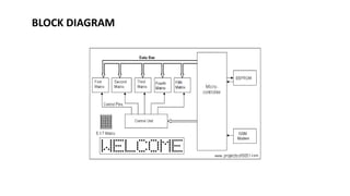
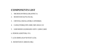
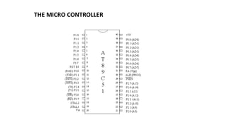
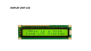
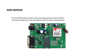
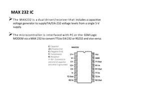
BABA INSTITUTE OF TECHNOLOGY AND SCIENCES
Main Project Report on
GSM BASED WIRELESS NOTICE BOARD
Presented by:
R.Indraja 467
R.Sathish 468
S.Tejaswini 475
P.Vamsi Krishna 410
Under the guidance of Divya Mam
Contents
1. AIM OF THE PROJECT
2. EXISTING SYSTEMS IN MARKET
3. INTRDUCTION
4. SCOPE OF WORK AND IDEA
5. BLOCK DIAGRAM
6. CIRCUIT DIAGRAM
7. COMPONENT LIST
8. THE MICROCONTROLLER
9. DISPLAYUNIT(LCD)
10.GSM MODULE
11.MAX232 IC
12.APPLICATION AND PURPOSE
13.FURTHER ENHANCEMENT
14.FUTURE SCOPE
15.CONCLUSION
AIM OF THE PROJECT
The main aim of the project will be to design a GSM based electronic notice
display system which Can replace the currently used programmable electronic display.
We can display anything we want through the use of a SMS via a mobile through
implementation of a GSM modem in the project.
EXISTING SYSTEMS IN MARKET
 currently programmable electronic display are notwireless and SMS based display
of information on notice board.
• There remains a particular message in the programming phenomenon of the system.
INTRODUCTION
The message containing the information would bedisplay on the LCD screen via a GSM
modem.
The SMS message to be displayed is sent through afrom an authorized transmitter.
The microcontroller receives the SMS, validates The sending mobile identification
number (MIN) and displays desired information
SCOPE OF WORK AND IDEA
 In contolling the appliances using wireless Communication and Embedded Systems
 Work on “Embedded System in Communication” is widely do in this project.
 The mian idea is that a GSM modem receives a SMS and the Microcontroller validates the SMS and then displays
the message in the LCD display board
BLOCK DIAGRAM
CIRCUTE DIAGRAM
COMPONENTS LIST
1. MICROCONTROLLER(AT89C51)
2. RESISTANCE(470,330,1K)
3. CRYSTALOSCILLATOR(11.0592MHZ)
4. CAPACITORS(33PF,10MF,1MF) MAX 232
5. GSM MODULE(SIMADO GDT11 )SIM CARD
6. POWER ADEPTER(+5V)
7. LCD DISPLAY(4*20TEXT LCD)
8. RESISTANCE ARRAY(10K)
THE MICRO CONTROLLER
DISPLAY UNIT LCD
GSM MODEM
The low GSM modem provides acost, long range,wireless communication
channel for applications that need high connectivity rather thandata rates.
The MAX232 is a dual driver/receiver that includes a capacitive
voltage generator to supplyTIA/EIA-232 voltage levels from a single 5-V
supply.
The microcontroller is interfaced with PC or the GSM Logic
MODEM via a MAX 232 to convert TTLto EIA232 or RS232 and vice versa.
MAX 232 IC
INTERNAL ARCHITECTURE
APPLICATIONS
Institutional Use: In colleges an Univ.
Industrial organization
Railway station
Managing traffic
Advertisement
Banking system
Emergency message display in Hospitals
ADVANTAGES
 Faster and more efficient service
 Reduces human efforts
 Increases efficiency
 Reducing delays
 Reduces human errors.
 Digitalization of all campous.
 Low maintance cost
 Increase green economy.
 Save paper
 Long time display
DISADVANTAGES
 High installition cost.
 Dependency on N/W
 Limitation on character Led display
FURTHER ENHANCEMENT
Alphanumeric LCD’S have a limitation on size and character display. We can use a LEDARRAYS to remove
the limitation.
Robots can be controlled in a similar fashion by sending the commands to the robots. These commands are
read by using AT commandsand appropriate action is taken.
Farmers can turn on or off pump and drippers via gsm modem.
FUTURE SCOPE
 Temperature and time (RTC) display during periods when no messages are to be displayed.
 GSM based home security systems , GSM based robot control , GSM based DC motor
controller , GSM based stepper motor controller , GSM based voting machine control etc.
CONCLUSION
 We can use this project in college notice board , a professor can send message for the
immediate Gathering of students at department .
 It can be used on Highways for traffic control , like traffic on one side of the road may be
blocked in view of vvip movements or jam ahead
THANK YOU

NOTICE BOARD.pptx

  • 1.
    BABA INSTITUTE OFTECHNOLOGY AND SCIENCES Main Project Report on GSM BASED WIRELESS NOTICE BOARD Presented by: R.Indraja 467 R.Sathish 468 S.Tejaswini 475 P.Vamsi Krishna 410 Under the guidance of Divya Mam
  • 2.
    Contents 1. AIM OFTHE PROJECT 2. EXISTING SYSTEMS IN MARKET 3. INTRDUCTION 4. SCOPE OF WORK AND IDEA 5. BLOCK DIAGRAM 6. CIRCUIT DIAGRAM 7. COMPONENT LIST 8. THE MICROCONTROLLER 9. DISPLAYUNIT(LCD) 10.GSM MODULE 11.MAX232 IC 12.APPLICATION AND PURPOSE 13.FURTHER ENHANCEMENT 14.FUTURE SCOPE 15.CONCLUSION
  • 3.
    AIM OF THEPROJECT The main aim of the project will be to design a GSM based electronic notice display system which Can replace the currently used programmable electronic display. We can display anything we want through the use of a SMS via a mobile through implementation of a GSM modem in the project.
  • 4.
    EXISTING SYSTEMS INMARKET  currently programmable electronic display are notwireless and SMS based display of information on notice board. • There remains a particular message in the programming phenomenon of the system.
  • 5.
    INTRODUCTION The message containingthe information would bedisplay on the LCD screen via a GSM modem. The SMS message to be displayed is sent through afrom an authorized transmitter. The microcontroller receives the SMS, validates The sending mobile identification number (MIN) and displays desired information
  • 6.
    SCOPE OF WORKAND IDEA  In contolling the appliances using wireless Communication and Embedded Systems  Work on “Embedded System in Communication” is widely do in this project.  The mian idea is that a GSM modem receives a SMS and the Microcontroller validates the SMS and then displays the message in the LCD display board
  • 7.
  • 8.
  • 9.
    COMPONENTS LIST 1. MICROCONTROLLER(AT89C51) 2.RESISTANCE(470,330,1K) 3. CRYSTALOSCILLATOR(11.0592MHZ) 4. CAPACITORS(33PF,10MF,1MF) MAX 232 5. GSM MODULE(SIMADO GDT11 )SIM CARD 6. POWER ADEPTER(+5V) 7. LCD DISPLAY(4*20TEXT LCD) 8. RESISTANCE ARRAY(10K)
  • 10.
  • 11.
  • 12.
    GSM MODEM The lowGSM modem provides acost, long range,wireless communication channel for applications that need high connectivity rather thandata rates.
  • 13.
    The MAX232 isa dual driver/receiver that includes a capacitive voltage generator to supplyTIA/EIA-232 voltage levels from a single 5-V supply. The microcontroller is interfaced with PC or the GSM Logic MODEM via a MAX 232 to convert TTLto EIA232 or RS232 and vice versa. MAX 232 IC
  • 14.
  • 15.
    APPLICATIONS Institutional Use: Incolleges an Univ. Industrial organization Railway station Managing traffic Advertisement Banking system Emergency message display in Hospitals
  • 16.
    ADVANTAGES  Faster andmore efficient service  Reduces human efforts  Increases efficiency  Reducing delays  Reduces human errors.  Digitalization of all campous.  Low maintance cost  Increase green economy.  Save paper  Long time display
  • 17.
    DISADVANTAGES  High installitioncost.  Dependency on N/W  Limitation on character Led display
  • 18.
    FURTHER ENHANCEMENT Alphanumeric LCD’Shave a limitation on size and character display. We can use a LEDARRAYS to remove the limitation. Robots can be controlled in a similar fashion by sending the commands to the robots. These commands are read by using AT commandsand appropriate action is taken. Farmers can turn on or off pump and drippers via gsm modem.
  • 19.
    FUTURE SCOPE  Temperatureand time (RTC) display during periods when no messages are to be displayed.  GSM based home security systems , GSM based robot control , GSM based DC motor controller , GSM based stepper motor controller , GSM based voting machine control etc.
  • 20.
    CONCLUSION  We canuse this project in college notice board , a professor can send message for the immediate Gathering of students at department .  It can be used on Highways for traffic control , like traffic on one side of the road may be blocked in view of vvip movements or jam ahead
  • 21.