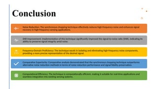
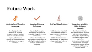
The Use of Synchronous
Chopping Technique in High-
Frequency Precision Sensing
Presented By: Rami Abdulrazzaq Aboud AlDulaimi
Supervisor: Dr. Mohamad Rahal
2
Outline
• Introduction
• Literature Review
• Methodology
• Results and Discussions
• Conclusion
• Future Work
3
Chopping Techniques in High-Frequency
Precision Sensing
Chopping is a technique used to reduce noise and offset errors in precision sensors.
It involves modulating the input signal and demodulating it to cancel out low-frequency noise and DC offsets.
How It Works:
Signal Modulation: The input signal is periodically switched (chopped) between two states.
Demodulation: After amplification, the signal is demodulated back to its original frequency, removing unwanted noise and offsets.
Applications:
Used in sensors requiring high accuracy such as accelerometers, gyroscopes, and medical devices.
Advantages:
Enhanced signal-to-noise ratio (SNR).
Improved measurement accuracy and stability.
Synchronous Detection in High-Frequency
Precision Sensing
• A technique to extract a signal from a noisy environment by synchronizing detection with a reference signal.
• Utilizes a reference signal that is in phase with the input signal for precise measurement.
• How It Works:
1. Reference Signal: A reference signal (often a square wave) is generated at the same frequency as the
input signal.
2. Mixing: The input signal is mixed with the reference signal.
3. Filtering: The resulting signal is filtered to remove high-frequency components, isolating the desired
signal.
• Applications:
• Widely used in applications like communications, signal processing, and instrumentation.
• Advantages:
• High immunity to noise and interference.
• Enhanced detection of weak signals.
4
5
O to Zero Chopping Technique in High-
Frequency Precision Sensing
O to Zero chopping is a specific technique used to mitigate offset and low-frequency noise in precision
measurement systems.
This technique involves alternating the signal path between an operational state (O) and a zero state, thereby
canceling out offset errors and noise.
How It Works:
Operational State (O): The input signal is processed normally through the measurement system.
Zero State: The input signal path is shorted or connected to a known reference (zero), effectively
measuring the system's offset and noise.
Subtraction: The measured offset and noise from the zero state are subtracted from the
operational state measurement, resulting in a more accurate signal.
Applications:
Widely used in high-precision analog-to-digital converters (ADCs) and operational amplifiers (op-
amps).
Beneficial in applications requiring high accuracy and stability, such as medical instrumentation
and precision sensors.
Advantages:
Significant reduction in offset errors.
Enhanced rejection of low-frequency noise.
Improved accuracy and stability of the measurement system.
Bioimpedance
• Bioimpedance is the measurement of the opposition of biological tissues to the flow of an electric current.
• It involves applying a small alternating current to the body and measuring the resulting voltage drop.
• Principles:
• Current Injection: A small AC current is injected into the body through surface electrodes.
• Voltage Measurement: The voltage drop is measured across the tissues, reflecting the impedance.
• Frequency Dependency: Bioimpedance varies with frequency, providing information about different tissue properties.
• Applications:
• Body Composition Analysis: Determining fat, muscle, and water content in the body.
• Cardiac Monitoring: Assessing cardiac output and fluid status.
• Respiratory Monitoring: Measuring changes in thoracic impedance to monitor breathing.
• Cancer Detection: Differentiating between healthy and malignant tissues based on their impedance characteristics.
• Advantages:
• Non-invasive and safe.
• Real-time monitoring capabilities.
• Useful for a wide range of clinical and research applications. 6
7
Importance of High-Frequency Precision
Sensing
• Crucial for real-time monitoring and control in industries like aerospace, automotive, and industrial
automation.
• Enables rapid adjustment of parameters to ensure operational efficiency and safety.
Significance of High-
Frequency Precision Sensing
• Essential for ultrasound, MRI, and CT scans to visualize internal structures with exceptional detail and
accuracy.
• Enables detection of abnormalities for precise medical diagnostics.
Role in Medical Imaging and
Diagnostics
• Critical for 5G networks, IoT devices, and radar systems.
• Ensures precise signal modulation, demodulation, and efficient spectrum utilization for reliable
communication.
Importance in Wireless
Communication Systems
• Assesses integrity of infrastructure, buildings, bridges, and mechanical systems.
• Early detection of defects and potential failures improves safety and prolongs asset lifespan.
Impact on Structural Health
Monitoring
• Facilitates study of dynamic phenomena in physics, chemistry, biology, and materials science.
• Supports innovation in autonomous vehicles, robotics, virtual reality, and augmented reality by
providing accurate sensory feedback.
Role in Scientific Research
and Emerging Technologies
8
Problems and Limitations
• Conventional techniques face challenges in accurately measuring high-frequency signals in critical applications
like telecommunications and medical imaging.
• Noise sources (thermal, electromagnetic interference) degrade signal quality, compromising accuracy.
• Bandwidth constraints, limited dynamic range, and nonlinearities further hinder precise measurement and
signal fidelity.
Problem Statement in High-Frequency Precision Sensing
• Noise: Thermal noise and electromagnetic interference reduce Signal-to-Noise Ratio (SNR), affecting sensitivity.
• Bandwidth: Sensors and circuits often have restricted bandwidth, limiting accurate signal capture and
processing.
• Nonlinearities: Introduce distortions and harmonic components, complicating data analysis and interpretation.
• Practical Challenges: Size constraints for portable devices, high power consumption, and cost implications
necessitate efficient design and management strategies.
Current Limitations in High-Frequency Sensing
Objectives
of Study
9
Investigate the Applicability of
Synchronous Chopping
Assess the Impact on High-Frequency
Precision Sensing
Explore Practical Considerations and
Implementation Challenges
Demonstrate Potential Applications and
Future Directions
10
Comparison Study
TECHNIQUE KEY FEATURES ADVANTAGES LIMITATIONS
Synchronous Chopping Modulation and
demodulation with carrier
signal
High SNR, effective noise
reduction
Requires precise
synchronization
Lock-In Amplification Reference signal, mixing,
low-pass filtering
Excellent for extracting
weak signals
Limited to specific
frequency ranges
Phase-Locked Loop (PLL) Phase synchronization,
feedback control
Precise frequency tracking Sensitive to phase noise
Heterodyne Detection Frequency conversion,
intermediate frequency
Simplifies high-frequency
signal processing
May introduce image
frequency interference
11
Applications and Case Studies (1/2)
Cancellation of Amplifier Offset and 1/f Noise: An
Improved Chopper Stabilized Technique [21]
A CMOS Chopper Offset-Stabilized Op-Amp [22]
12
Applications and Case Studies (2/2)
Circuit Techniques for Reducing the Effects of Op-Amp
Imperfections: Autozeroing, Correlated Double
Sampling, and Chopper Stabilization [23]
A Chopping and Doubly-Fed Adjustable
Speed System Without Bi-directional
Converter [24]
13
Implementation of Synchronous Chopping
Technique
Involves modulating the sensor's input signal at a specific frequency (ranging from tens of kilohertz to
several megahertz) to shift the signal away from low-frequency noise.
Determines how much the input signal is modulated, expressed as a percentage of the signal's peak-to-peak
amplitude, influencing noise suppression and potential nonlinear effects.
Crucial for maintaining coherence between modulated input signal and demodulation reference signal,
ensuring accurate demodulation and minimizing phase errors.
Technical
Specifications
Utilizes a voltage-controlled oscillator (VCO) or frequency synthesizer to generate modulated input signal,
controlling modulation depth via techniques like pulse-width modulation (PWM) or amplitude modulation
(AM).
Employs synchronous demodulation techniques such as lock-in amplifiers or phase-sensitive detectors to
extract demodulated signal synchronized with modulation frequency, filtering out low-frequency noise and
interference.
Involves digital techniques (e.g., filtering, averaging, spectral analysis) to further process demodulated
signal, enhancing signal-to-noise ratio and extracting meaningful information.
Integration
with Sensing
Systems
Ensures modulation-demodulation circuits and signal processing algorithms align with sensor's dynamic
range, frequency response, and noise characteristics for optimal performance.
Includes considerations like power consumption, size, and cost, influencing choice of components and
implementation approach.
Design
Considerations
14
Data Collection, Analysis, and Validation
Methods
Data Collection
Methods
• Setup Preparation: Configure
the signal generator, calibrate
the sensor, and align
components.
• Experimental Runs: Conduct
experiments under controlled
conditions, varying parameters
like frequency, amplitude, and
environmental factors.
• Data Recording: Use a data
acquisition system (DAQ) to
capture sensor readings,
including modulated input and
demodulated output signals, at
regular intervals. Record
additional environmental data
such as temperature, humidity,
and ambient noise.
Data Analysis Techniques
• Preprocessing: Clean and
normalize data by filtering
noise, correcting baseline drift,
and aligning data from multiple
sources.
• Statistical Analysis: Use
statistical methods (mean,
median, standard deviation,
correlation) to summarize data
and identify trends or patterns.
• Signal Processing: Apply
techniques like Fourier
transform, wavelet transform,
and spectral analysis to
examine frequency content and
signal characteristics
(amplitude, frequency, phase).
Validation of Results
• Internal Validation: Check
consistency and reproducibility
of results within the study by
comparing data from different
experimental conditions and
measurement techniques.
• External Validation: Compare
results with data from
independent sources or
published literature to ensure
consistency and reliability.
15
Initial Findings
16
Performance Analysis of Synchronous
Chopping Technique
17
Comparison with Alternative Techniques
18
Comparison with Alternative Techniques
19
Comparison Summary
• Synchronous Chopping Technique: Achieved the highest Signal-to-Noise Ratio (SNR) improvement of 22.8 dB with
minimal signal distortion.
• Low-Pass Filtering Alone: Resulted in an SNR improvement of 10.5 dB.
• Averaging Methods: Resulted in an SNR improvement of 15.2 dB.
SNR Improvement:
• The synchronous chopping technique was superior in reducing noise and preserving the signal's integrity compared
to the other methods.
• Low-pass filtering alone and averaging methods provided some noise reduction but were less effective in isolating
and removing high-frequency noise components.
• These alternative methods resulted in lower SNR improvements and higher levels of signal distortion.
Noise Reduction and Signal Preservation:
• The synchronous chopping technique's ability to modulate and demodulate the signal, shifting noise components to
higher frequencies where they could be effectively filtered out, gave it a significant advantage over low-pass filtering
and averaging.
Technical Advantages:
20
Conclusion
Noise Reduction: The synchronous chopping technique effectively reduces high-frequency noise and enhances signal
recovery in high-frequency sensing applications.
SNR Improvement: Implementation of this technique significantly improved the signal-to-noise ratio (SNR), indicating its
ability to preserve signal integrity amid noise.
Frequency-Domain Proficiency: The technique excels in isolating and eliminating high-frequency noise components,
providing a more precise representation of the desired signal.
Comparative Superiority: Comparative analysis demonstrated that the synchronous chopping technique outperforms
alternative noise reduction methods in terms of noise reduction performance and signal fidelity preservation.
Computational Efficiency: The technique is computationally efficient, making it suitable for real-time applications and
seamless integration into existing sensing systems.
21
Future Work
Optimization of Chopping
Frequency:
Develop algorithms to
automatically adjust the
chopping frequency based on
signal and noise characteristics.
Improve performance by
ensuring the chopping frequency
is optimally tuned for varying
conditions.
Adaptive Chopping
Techniques:
Explore adaptive chopping
methods that can dynamically
respond to changes in the noise
environment.
Enhance the versatility and
effectiveness of the technique by
allowing it to adjust in real-time
to varying signal and noise
conditions.
Real-World Applications:
Test the technique in practical
scenarios such as biomedical
signal processing and industrial
sensing.
Validate the robustness and
effectiveness of the synchronous
chopping technique in diverse
environments.
Integration with Other
Noise Reduction
Methods:
Investigate combining the
synchronous chopping technique
with other noise reduction
strategies like adaptive filtering
and machine learning-based
approaches.
Aim to further enhance overall
performance by providing a
comprehensive solution for noise
reduction in high-frequency
precision sensing.
22
Thank you

New Microsoft PowerPoint Presentation.pptx

  • 1.
    The Use ofSynchronous Chopping Technique in High- Frequency Precision Sensing Presented By: Rami Abdulrazzaq Aboud AlDulaimi Supervisor: Dr. Mohamad Rahal
  • 2.
    2 Outline • Introduction • LiteratureReview • Methodology • Results and Discussions • Conclusion • Future Work
  • 3.
    3 Chopping Techniques inHigh-Frequency Precision Sensing Chopping is a technique used to reduce noise and offset errors in precision sensors. It involves modulating the input signal and demodulating it to cancel out low-frequency noise and DC offsets. How It Works: Signal Modulation: The input signal is periodically switched (chopped) between two states. Demodulation: After amplification, the signal is demodulated back to its original frequency, removing unwanted noise and offsets. Applications: Used in sensors requiring high accuracy such as accelerometers, gyroscopes, and medical devices. Advantages: Enhanced signal-to-noise ratio (SNR). Improved measurement accuracy and stability.
  • 4.
    Synchronous Detection inHigh-Frequency Precision Sensing • A technique to extract a signal from a noisy environment by synchronizing detection with a reference signal. • Utilizes a reference signal that is in phase with the input signal for precise measurement. • How It Works: 1. Reference Signal: A reference signal (often a square wave) is generated at the same frequency as the input signal. 2. Mixing: The input signal is mixed with the reference signal. 3. Filtering: The resulting signal is filtered to remove high-frequency components, isolating the desired signal. • Applications: • Widely used in applications like communications, signal processing, and instrumentation. • Advantages: • High immunity to noise and interference. • Enhanced detection of weak signals. 4
  • 5.
    5 O to ZeroChopping Technique in High- Frequency Precision Sensing O to Zero chopping is a specific technique used to mitigate offset and low-frequency noise in precision measurement systems. This technique involves alternating the signal path between an operational state (O) and a zero state, thereby canceling out offset errors and noise. How It Works: Operational State (O): The input signal is processed normally through the measurement system. Zero State: The input signal path is shorted or connected to a known reference (zero), effectively measuring the system's offset and noise. Subtraction: The measured offset and noise from the zero state are subtracted from the operational state measurement, resulting in a more accurate signal. Applications: Widely used in high-precision analog-to-digital converters (ADCs) and operational amplifiers (op- amps). Beneficial in applications requiring high accuracy and stability, such as medical instrumentation and precision sensors. Advantages: Significant reduction in offset errors. Enhanced rejection of low-frequency noise. Improved accuracy and stability of the measurement system.
  • 6.
    Bioimpedance • Bioimpedance isthe measurement of the opposition of biological tissues to the flow of an electric current. • It involves applying a small alternating current to the body and measuring the resulting voltage drop. • Principles: • Current Injection: A small AC current is injected into the body through surface electrodes. • Voltage Measurement: The voltage drop is measured across the tissues, reflecting the impedance. • Frequency Dependency: Bioimpedance varies with frequency, providing information about different tissue properties. • Applications: • Body Composition Analysis: Determining fat, muscle, and water content in the body. • Cardiac Monitoring: Assessing cardiac output and fluid status. • Respiratory Monitoring: Measuring changes in thoracic impedance to monitor breathing. • Cancer Detection: Differentiating between healthy and malignant tissues based on their impedance characteristics. • Advantages: • Non-invasive and safe. • Real-time monitoring capabilities. • Useful for a wide range of clinical and research applications. 6
  • 7.
    7 Importance of High-FrequencyPrecision Sensing • Crucial for real-time monitoring and control in industries like aerospace, automotive, and industrial automation. • Enables rapid adjustment of parameters to ensure operational efficiency and safety. Significance of High- Frequency Precision Sensing • Essential for ultrasound, MRI, and CT scans to visualize internal structures with exceptional detail and accuracy. • Enables detection of abnormalities for precise medical diagnostics. Role in Medical Imaging and Diagnostics • Critical for 5G networks, IoT devices, and radar systems. • Ensures precise signal modulation, demodulation, and efficient spectrum utilization for reliable communication. Importance in Wireless Communication Systems • Assesses integrity of infrastructure, buildings, bridges, and mechanical systems. • Early detection of defects and potential failures improves safety and prolongs asset lifespan. Impact on Structural Health Monitoring • Facilitates study of dynamic phenomena in physics, chemistry, biology, and materials science. • Supports innovation in autonomous vehicles, robotics, virtual reality, and augmented reality by providing accurate sensory feedback. Role in Scientific Research and Emerging Technologies
  • 8.
    8 Problems and Limitations •Conventional techniques face challenges in accurately measuring high-frequency signals in critical applications like telecommunications and medical imaging. • Noise sources (thermal, electromagnetic interference) degrade signal quality, compromising accuracy. • Bandwidth constraints, limited dynamic range, and nonlinearities further hinder precise measurement and signal fidelity. Problem Statement in High-Frequency Precision Sensing • Noise: Thermal noise and electromagnetic interference reduce Signal-to-Noise Ratio (SNR), affecting sensitivity. • Bandwidth: Sensors and circuits often have restricted bandwidth, limiting accurate signal capture and processing. • Nonlinearities: Introduce distortions and harmonic components, complicating data analysis and interpretation. • Practical Challenges: Size constraints for portable devices, high power consumption, and cost implications necessitate efficient design and management strategies. Current Limitations in High-Frequency Sensing
  • 9.
    Objectives of Study 9 Investigate theApplicability of Synchronous Chopping Assess the Impact on High-Frequency Precision Sensing Explore Practical Considerations and Implementation Challenges Demonstrate Potential Applications and Future Directions
  • 10.
    10 Comparison Study TECHNIQUE KEYFEATURES ADVANTAGES LIMITATIONS Synchronous Chopping Modulation and demodulation with carrier signal High SNR, effective noise reduction Requires precise synchronization Lock-In Amplification Reference signal, mixing, low-pass filtering Excellent for extracting weak signals Limited to specific frequency ranges Phase-Locked Loop (PLL) Phase synchronization, feedback control Precise frequency tracking Sensitive to phase noise Heterodyne Detection Frequency conversion, intermediate frequency Simplifies high-frequency signal processing May introduce image frequency interference
  • 11.
    11 Applications and CaseStudies (1/2) Cancellation of Amplifier Offset and 1/f Noise: An Improved Chopper Stabilized Technique [21] A CMOS Chopper Offset-Stabilized Op-Amp [22]
  • 12.
    12 Applications and CaseStudies (2/2) Circuit Techniques for Reducing the Effects of Op-Amp Imperfections: Autozeroing, Correlated Double Sampling, and Chopper Stabilization [23] A Chopping and Doubly-Fed Adjustable Speed System Without Bi-directional Converter [24]
  • 13.
    13 Implementation of SynchronousChopping Technique Involves modulating the sensor's input signal at a specific frequency (ranging from tens of kilohertz to several megahertz) to shift the signal away from low-frequency noise. Determines how much the input signal is modulated, expressed as a percentage of the signal's peak-to-peak amplitude, influencing noise suppression and potential nonlinear effects. Crucial for maintaining coherence between modulated input signal and demodulation reference signal, ensuring accurate demodulation and minimizing phase errors. Technical Specifications Utilizes a voltage-controlled oscillator (VCO) or frequency synthesizer to generate modulated input signal, controlling modulation depth via techniques like pulse-width modulation (PWM) or amplitude modulation (AM). Employs synchronous demodulation techniques such as lock-in amplifiers or phase-sensitive detectors to extract demodulated signal synchronized with modulation frequency, filtering out low-frequency noise and interference. Involves digital techniques (e.g., filtering, averaging, spectral analysis) to further process demodulated signal, enhancing signal-to-noise ratio and extracting meaningful information. Integration with Sensing Systems Ensures modulation-demodulation circuits and signal processing algorithms align with sensor's dynamic range, frequency response, and noise characteristics for optimal performance. Includes considerations like power consumption, size, and cost, influencing choice of components and implementation approach. Design Considerations
  • 14.
    14 Data Collection, Analysis,and Validation Methods Data Collection Methods • Setup Preparation: Configure the signal generator, calibrate the sensor, and align components. • Experimental Runs: Conduct experiments under controlled conditions, varying parameters like frequency, amplitude, and environmental factors. • Data Recording: Use a data acquisition system (DAQ) to capture sensor readings, including modulated input and demodulated output signals, at regular intervals. Record additional environmental data such as temperature, humidity, and ambient noise. Data Analysis Techniques • Preprocessing: Clean and normalize data by filtering noise, correcting baseline drift, and aligning data from multiple sources. • Statistical Analysis: Use statistical methods (mean, median, standard deviation, correlation) to summarize data and identify trends or patterns. • Signal Processing: Apply techniques like Fourier transform, wavelet transform, and spectral analysis to examine frequency content and signal characteristics (amplitude, frequency, phase). Validation of Results • Internal Validation: Check consistency and reproducibility of results within the study by comparing data from different experimental conditions and measurement techniques. • External Validation: Compare results with data from independent sources or published literature to ensure consistency and reliability.
  • 15.
  • 16.
    16 Performance Analysis ofSynchronous Chopping Technique
  • 17.
  • 18.
  • 19.
    19 Comparison Summary • SynchronousChopping Technique: Achieved the highest Signal-to-Noise Ratio (SNR) improvement of 22.8 dB with minimal signal distortion. • Low-Pass Filtering Alone: Resulted in an SNR improvement of 10.5 dB. • Averaging Methods: Resulted in an SNR improvement of 15.2 dB. SNR Improvement: • The synchronous chopping technique was superior in reducing noise and preserving the signal's integrity compared to the other methods. • Low-pass filtering alone and averaging methods provided some noise reduction but were less effective in isolating and removing high-frequency noise components. • These alternative methods resulted in lower SNR improvements and higher levels of signal distortion. Noise Reduction and Signal Preservation: • The synchronous chopping technique's ability to modulate and demodulate the signal, shifting noise components to higher frequencies where they could be effectively filtered out, gave it a significant advantage over low-pass filtering and averaging. Technical Advantages:
  • 20.
    20 Conclusion Noise Reduction: Thesynchronous chopping technique effectively reduces high-frequency noise and enhances signal recovery in high-frequency sensing applications. SNR Improvement: Implementation of this technique significantly improved the signal-to-noise ratio (SNR), indicating its ability to preserve signal integrity amid noise. Frequency-Domain Proficiency: The technique excels in isolating and eliminating high-frequency noise components, providing a more precise representation of the desired signal. Comparative Superiority: Comparative analysis demonstrated that the synchronous chopping technique outperforms alternative noise reduction methods in terms of noise reduction performance and signal fidelity preservation. Computational Efficiency: The technique is computationally efficient, making it suitable for real-time applications and seamless integration into existing sensing systems.
  • 21.
    21 Future Work Optimization ofChopping Frequency: Develop algorithms to automatically adjust the chopping frequency based on signal and noise characteristics. Improve performance by ensuring the chopping frequency is optimally tuned for varying conditions. Adaptive Chopping Techniques: Explore adaptive chopping methods that can dynamically respond to changes in the noise environment. Enhance the versatility and effectiveness of the technique by allowing it to adjust in real-time to varying signal and noise conditions. Real-World Applications: Test the technique in practical scenarios such as biomedical signal processing and industrial sensing. Validate the robustness and effectiveness of the synchronous chopping technique in diverse environments. Integration with Other Noise Reduction Methods: Investigate combining the synchronous chopping technique with other noise reduction strategies like adaptive filtering and machine learning-based approaches. Aim to further enhance overall performance by providing a comprehensive solution for noise reduction in high-frequency precision sensing.
  • 22.

Editor's Notes

  • #10 high-frequency precision sensing relies on a variety of methods to achieve accurate and reliable measurements. The synchronous chopping technique stands out for its noise reduction capabilities, making it ideal for applications where signal clarity is critical. However, alternative techniques like lock-in amplification, PLLs, and heterodyne detection also play vital roles in specific contexts, offering unique benefits and addressing particular challenges. A thorough understanding of these methods and their comparative performance is essential for selecting the most appropriate technique for any given high-frequency sensing application.
  • #11 Cancellation of Amplifier Offset and 1/f Noise: An Improved Chopper Stabilized Technique [21] This paper addresses limitations in conventional chopper stabilization for precision sensing by proposing a modified chopping method, achieving over 40 dB noise reduction and maintaining signal integrity with minimal overhead. A CMOS Chopper Offset-Stabilized Op-Amp [22] The paper introduces an op-amp design with integrated chopper amplifier for offset cancellation, achieving high precision with less than 1.5 V offset at 16 kHz, 1.3 MHz unity gain frequency, and low power consumption, suitable for practical electronic applications.
  • #12 Circuit Techniques for Reducing the Effects of Op-Amp Imperfections: Autozeroing, Correlated Double Sampling, and Chopper Stabilization [23] This paper reviews techniques to mitigate amplifier imperfections in low-voltage CMOS ICs, focusing on reducing DC offset and low-frequency noise to improve dynamic range and gain. It discusses strategies like autozeroing, correlated double sampling, and chopper stabilization to enhance performance and reliability. A Chopping and Doubly-Fed Adjustable Speed System Without Bi-directional Converter [24] The paper proposes an innovative speed control method for doubly fed machines that eliminates the need for a bi-directional converter. By integrating rectifier, chopper, and inverter functions and using advanced control algorithms, it achieves effective speed control and reactive power regulation, offering a cost-efficient solution for adjustable speed applications.
  • #15 The MATLAB code generates the time-domain plots for the different signals. Each plot is displayed in a separate figure with a white background, showing the signals' amplitude as a function of time. These plots illustrate the effectiveness of the synchronous chopping technique in reducing noise and recovering the original signal.
  • #16 The MATLAB code generates the frequency-domain plots for the different signals. Each plot is displayed in a separate figure with a white background, showing the signals' magnitude as a function of frequency. These plots illustrate the spectral characteristics of the signals and the effectiveness of the synchronous chopping technique in isolating and reducing high-frequency noise components. The frequency-domain analysis ed revealed that the demodulated signal had a spectral peak at 0 Hz, corresponding to the original signal's DC component. The low-pass filter effectively removed the high-frequency noise components, resulting in a clean spectrum for the recovered signal, with a distinct peak at 50 Hz. The absence of significant noise components in the recovered signal's spectrum indicated that the synchronous chopping technique successfully isolated and removed the high-frequency noise, preserving the original signal's spectral characteristics.
  • #17 The MATLAB code demonstrates the application of a low-pass filter directly to the noisy signal. The filtered signal was plotted in both the time domain and the frequency domain. The time-domain plot showed some reduction in noise, but the signal remained significantly distorted. The frequency-domain plot revealed that the low-pass filter attenuated the high-frequency noise components but was less effective in removing noise components within the signal's frequency band.
  • #18 The MATLAB code demonstrates the application of a moving average filter to the noisy signal. The filtered signal was plotted in both the time domain and the frequency domain. The time-domain plot showed moderate noise reduction but also significant signal distortion, especially at the edges of the signal. The frequency-domain plot revealed that the moving average filter attenuated the high-frequency noise components but introduced blurring and distortion to the signal.
  • #19 A comparative analysis was conducted between the synchronous chopping technique, low-pass filtering alone, and averaging methods in terms of their effectiveness in noise reduction and signal preservation. The key findings are:
  • #20 This study evaluated the efficacy of the synchronous chopping technique for high-frequency precision sensing, leading to several significant findings:
  • #21 Future research will focus on several key areas to enhance the synchronous chopping technique for high-frequency precision sensing: