Downloaded 153 times
![NASA Systems Engineering Handbook Page iii
Foreword to the September 1992 Draft As such, this present document is to be
considered a next-to-final draft. Your comments,
When NASA began to sponsor agency – corrections and suggestions are welcomed, valued
wide classes in systems engineering, it was to a and appreciated. Please send your remarks directly to
doubting audience. Top management was quick to Robert Shishko, NASA Systems
express concern. As a former Deputy Administrator Engineering Working Group. NASA/Jet Propulsion
stated "How can you teach an agency-wide systems Laboratory, California Institute of Technology,
engineering class when we cannot even agree on 4800 Oak Grove Drive, Pasadena, CA
how to define it?" Good question, and one I must 91109-8099.
admit caused us considerable concern at that time. —Francis T. Hoban
The same doubt continued up until the publication of Program Manager, NASA Headquarters
this handbook.
The initial systems engineering education
conference was held in January 1989 at the Johnson
Space Center. A number of representatives from
other Centers at tended this meeting and it was
decided then that we needed to form a working group
to support the development of appropriate and
tailored systems engineering courses. At this meeting
the representatives from Marshal1 Space Flight
Center (MSFC) expressed a strong desire to docu
ment their own historic systems engineering process
before any more of the key players left the Center.
Other Centers also expressed a desire, if not as
urgent as MSFC, to document their processes.
It was thought that the best way to reflect the
totality of the NASA systems engineering process and
to aid in developing the needed training was to
prepare a top level (Level 0) document that would
contain a broad definition of systems engineering, a
broad process outline, and typi cal tools and
procedures. In general, we wanted a top level
overview of NASA systems engineering. To this
document would be appended each Center's unique
systems engineering manual. The group was well
aware of the diversity each Center may have, but
agreed that this approach would be quite acceptable.
The next step and the most difficult in this
arduous process was to find someone to head this
yet-to-be-formed working group. Fortunately for
NASA, Donna [Pivirotto] Shirley of the Jet Propulsion
Laboratory stepped up to the challenge. Today,
through her efforts, those of the working group, and
the skilled and dedicated authors, we have a unique
and possibly a historic document.
During the development of the manual we
decided to put in much more than may be appropriate
for a Level 0 document with the idea that we could
always refine the document later. It was more
important to capture the knowledge when we could in
order to better position our selves for later
dissemination. If there is any criticism, it may be the
level of detail contained in the manual, but this detail
is necessary for young engineers. The present
document does appear to serve as a good
instructional guide, although it does go well beyond its
original intent.](https://image.slidesharecdn.com/nasaengineeringhandbookpdf-120419192949-phpapp01/85/NASA-Engineering-Handbook-3-320.jpg)

![NASA Systems Engineering Handbook Page 67
how individuals should behave when confronted by
uncertainty. Practical application of this rule requires This section deals with the role of costs in
an ability to enumerate each "state of nature" the systems analysis and engineering process, how to
(hereafter, simply called "state"), knowledge of the measure it, how to control it, and how to obtain
outcome associated with each enumerated state for estimates of it. The reason costs and their estimates
each alternative, the probabilities for the various are of great importance in systems engineering goes
states, and a mathematical expression for the back to the principal objective of systems engineering:
decision maker's utility function. This selection rule fulfilling the system's goals in the most cost-effective
has also found use in the evaluation of system manner. The cost of each alternative should be one of
procurement alternatives. See Section 4.6.3 for a the most important outcome variables in trade studies
discussion of some related topics, including decision performed during the systems engineering process.
analysis, decision trees, and probabilistic risk One role, then, for cost estimates is in
assessment. helping to choose rationally among alternatives.
Another selection rule for this class of Another is as a control mechanism during the project
decision problem is called the minimax rule. To apply life cycle. Cost measures produced for project life
it, the sys-tem engineer computes a loss function for cycle reviews are important in determining whether
each enumerated state for each alternative. This rule the system goals and objectives are still deemed valid
chooses the alternative that minimizes the maximum and achievable, and whether constraints and
loss. Practical application requires an ability to boundaries are worth maintaining. These measures
enumerate each state and define the loss function. are also useful in determining whether system goals
Because of its "worst case" feature, this rule has and objectives have properly flowed down through to
found some application in military systems. the various subsystems.
As system designs and operational concepts
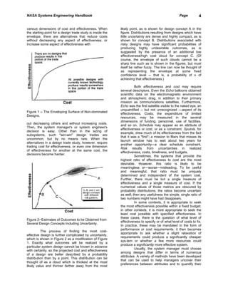
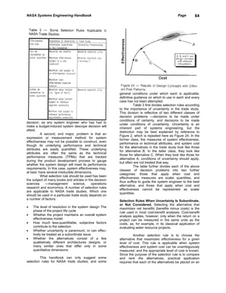
5.1.4 Trade Study Process: Summary mature, cost estimates should mature as well. At each
review, cost estimates need to be presented and
System architecture and design decisions will be compared to the funds likely to be available to
made. The purpose of the trade study process is to complete the project. The cost estimates presented at
ensure that they move the design toward an optimum. early reviews must be given special attention since
The basic steps in that process are: they usually form the basis under which authority to
proceed with the project is given. The system
Understand what the system's goals, objectives, and engineer must be able to provide realistic cost
constraints are, and what the system must do to meet estimates to the project manager. In the absence of
them—that is, understand the functional requirements such estimates, overruns are likely to occur, and the
in the operating environment. credibility of the entire system development process,
Devise some alternative means to meet the functional both internal and exter-nal, is threatened.
requirements. In the early phases of the project life
cycle, this means focusing on system architectures; in 5.2.1 Life-Cycle Cost and Other Cost
later phases, emphasis is given to system designs. Measures
Evaluate these alternatives in terms of the outcome
variables (system effectiveness, its underlying A number of questions need to be addressed so that
performance or technical attributes, and system cost). costs are properly treated in systems analysis and
Mathematical models are useful in this step not only engineering. These questions include:
for forcing recognition of the relationships among the
outcome variables, but also for helping to determine • What costs should be counted?
what the performance requirements must be • How should costs occurring at different times be
quantitatively. treated?
Rank the alternatives according to an appropriate • What about costs that cannot easily be measured
selection rule. in dollars?
Drop less-promising alternatives and proceed to next
level of resolution, if needed. What Costs Should be Counted. The most
comprehensive measure of the cost of an alternative
This process cannot be done as an isolated is its life-cycle cost. According to NHB 7120.5, a
activity. To make it work effectively, individuals with system's life-cycle cost is "the total of the direct,
different skills—system engineers, design engineers, indirect, recurring, nonrecurring, and other related
specialty engineers, program analysts, decision costs incurred, or estimated to be incurred in the
scientists, and project managers—must cooperate. design, development, production, operation,
The right quantitative methods and selection rule maintenance, support, and retirement [of it] over its
must be used. Trade study assumptions, models, and planned life span." A less formal definition of a
results must be documented as part of the project system's life-cycle cost is the total cost of acquiring,
archives. owning, and disposing of it over its entire lifetime.
System life-cycle cost should be estimated and used
5.2 Cost Definition and Modeling in the evaluation of alternatives during trade studies.](https://image.slidesharecdn.com/nasaengineeringhandbookpdf-120419192949-phpapp01/85/NASA-Engineering-Handbook-74-320.jpg)
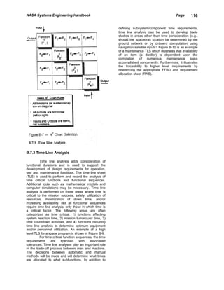
![NASA Systems Engineering Handbook Page 81
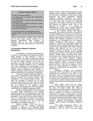
Reliability can be defined as the probability The reliability engineer works with other
that a device, product, or system will not fail for a specialty engineers (e.g., the quality assurance,
given period of time under specified operating maintainability, verification, and producibility
conditions. Reliability is an inherent system design engineers) on system reliability issues. On small
characteristic. As a principal contributing factor in projects, the reliability engineer may perform some or
operations and support costs and in system all of these other jobs as well.
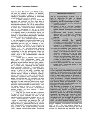
effectiveness (see Figure 26), reliability plays a key
role in determining the system's cost-effectiveness. 6.2.2 Reliability Program Planning
6.2.1 Role of the Reliability Engineer The reliability program for a project
describes what activities will be undertaken in support
Reliability engineering is a major specialty of reliability engineering. The reliability engineer
disci-pline that contributes to the goal of a cost- develops a reliability program considering its cost,
effective system. This is primarily accomplished in the schedule, and risk implications. This planning should
systems engineering process through an active role in begin during Phase A. The project manager/system
implementing specific design features to ensure that engineer must work with the reliability engineer to
the system can perform in the predicted physical develop an appropriate reliability program as many
environments throughout the mission, and by making factors need to be considered in developing this
independent predictions of system reliability for program. These factors include:
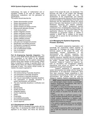
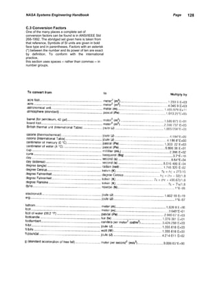
design trades and for (test program, operations, and Lunar Excursion Module (LEM) Reliability
integrated logistics support) planning.
The reliability engineer performs several Part of the reliability engineer's job is to develop
tasks, which are explained in more detail in NHB an understanding of the underlying physical and
5300.4(1A -1), Reliability Program Requirements for human-induced causes of failures, rather than
Aeronautical and Space System Contractors. In brief, assuming that all failures are random. According
these tasks include: to Joseph Gavin, Director of the LEM Program at
Grumman, "after about 10 years of testing of
• Developing and executing a reliability program individual [LEM] components and subsystems,
plan [NASA] found something like 14,000 anomalies,
• Developing and refining reliability prediction only 22 of which escaped definite understanding.”
models, including associated environmental (e.g.,
vibration, acoustic, thermal, and EMI/EMC)
models, and predictions of system reliability.
These models and predictions should reflect • NASA payload classification. The reliability
applicable experience from previous projects. program's analytic content and its documentation
• Establishing and allocating reliability goals and of problems and failures are generally more
environmental design requirements extensive for a Class A payload than for a Class
• Supporting design trade studies covering such D one. (See Appendix B.3 for classification
issues as the degree of redundancy and reliability guidelines.)
vs. maintainability • Mission environmental risks. Several mission
• Supporting risk management by identifying environmental models may need to be
design attributes likely to result in reliability developed. For flight projects, these include
problems and recommending appropriate risk ground (transportation and handling), launch, on-
mitigations orbit (Earth or other), and planetary
• Developing reliability data for timely use in the environments. In addition, the reliability engineer
project's maintainability and ILS programs must address design and verification
• Developing environmental test requirements and requirements for each such environment.
specifications for hardware qualification. The • Degree of design inheritance and
reliability engineer may provide technical analysis hardware/software reuse.
and justification for eliminating or relaxing
qualification test requirements. These activities The reliability engineer should document the
are usually closely coordinated with the project's reliability program in a reliability program plan, which
verification program. should be summarized in the SEMP (Part III) and
• Performing analyses on qualification test data to updated as needed through the project life cycle; the
verify reliability predictions and validate the summary may be sufficient for small projects.
system reliability prediction models, and to
understand and resolve anomalies
• Collecting reliability data under actual operations
conditions as a part of overall system validation.](https://image.slidesharecdn.com/nasaengineeringhandbookpdf-120419192949-phpapp01/85/NASA-Engineering-Handbook-88-320.jpg)
![NASA Systems Engineering Handbook Page 95
requirement is to be verified, the stage in which requirements for that verification activity only. The
verification is to occur, and (sometimes) the verification engineer develops the VRSD from an
applicable verification levels. The verification engineer understanding of the requirements, the verification
develops the VRM in coordination with the design, program concept, and the flight article. The VRSD is
systems engineering, and test organizations. VRM baselined prior to the start of the verification activity.
contents are tailored to each project's requirements, The heart of the VRSD is a data table that includes
and the level of detail in VRMs may vary. The VRM is the following fields:
baselined as a result of the PDR, and essentially
establishes the basis for the verification program. A A numerical designator assigned to each requirement
sample VRM for a CI specification is shown in A statement of the specific requirement to be verified
Appendix B.9. The "pass/fail" criteria and tolerances for each
requirement
Master Verification Plan. The Master Verification Any constraints that must be observed
Plan (MVP) is the document that describes the overall Any remarks to aid in the understanding of the
verification program. The MVP provides the content requirement
and depth of detail necessary to provide full visibility Location where the requirement will be verified.
of all verification activities. Each major activity is
defined and described in detail. The plan The VRSD, along with flight article drawings
encompasses qualification, acceptance, pre-launch, and schematics, is the basis for the development of
operational, and disposal verification activities for verification procedures, and is also used as one of the
flight hardware and software. (Development stage bases for development of the Verification
verification activities are not normally documented in Requirements Compliance Document (VRCD).
the plan, but may be documented elsewhere.) The
plan provices a general schedule and sequence of Verification Requirements Compliance Document.
events for major verification activities. It also The Verification Requirements Compliance Document
describes test software, Ground Support Equipment (VRCD) provides the evidence of compliance to each
(GSE), and facilities necessary to support the Level I through Level n design, performance, safety,
verification activities. The verification engineer and interface requirement, and to each VRSD
develops the plan through a thorough understanding requirement. The flowdown to VRSD requirements
of the verification program concept, the requirements completes the full requirements traceability.
in the Program (i.e., Level I) Requirements Document Compliance with all the requirements ensures that
(PRD), System/Segment (i.e., Level II) Requirements Level I requirements have been met.
Document (SRD), and/or the CI specification, and the The VRCD defines, for each requirement,
methods identified in the VRM of those documents. the method(s) of verification and corresponding
Again, the development of the plan requires that the compliance information for each method employed.
verification engineer work closely with the design, The compliance information provides either the actual
systems engineering, and test organizations. A data, or a reference to the location of the actual data
sample outline for this plan is illustrated in Appendix that shows compliance with the requirement. (The
B.10. document also shows any non-compliances by
referencing the related Non-Compliance Report
Verification Requirements and Specifications (NCR) or Problem/Failure Report (P/FR); following
Docu -ment. The Verification Requirements and resolution of the anomaly, the document specifies
Specifications Document (VRSD) defines the detailed appropriate re-verification information.) The
requirements and specifications for the verification of compliance information may reference a verification
a flight article, including the ground system/segment. report, an automated test program, a verification
The VRSD specifies requirements and specifications procedure, an analysis report, or a test. The inputting
for activities covering qualification through operational of compliance information into the compliance
verification. Requirements are also defined for flight document occurs over a lengthy period of time, and
software verification after the software has been on large systems and payloads, the effort may be
installed in the flight article. The VRSD should cover continuous. The information in the compliance
verifications by all methods; some programs/projects, document must be up-to-date for the System
however, use a document that defines only Acceptance Review(s) (SAR) and Flight Readiness
requirements to be satisfied by test. The VRSD Review (FRR). The compliance document is not
should include all requirements defined in Level I, II, baselined because compliance information is input to
and III requirements documents plus derived the document throughout the entire project life cycle.
requirements. The VRSD defines the acceptance It is, however, an extremely important part of the
criteria and any constraints for each requirement. The project's archives.
VRSD typical]y identifies the locations where The heart of the Verification Requirements
requirements will be verified. On large Compliance Document is also a data table with links
programs/projects, a VRSD is normally developed for to the corresponding requirements. The VRCD
each verification activity/location (e.g., thermal- includes the following fields:
vacuum testing), and is tailored to include](https://image.slidesharecdn.com/nasaengineeringhandbookpdf-120419192949-phpapp01/85/NASA-Engineering-Handbook-102-320.jpg)
![NASA Systems Engineering Handbook Page 104
PPAR Preliminary Program/Project Approval E. Broad St., Athens GA 30602
Review GISS Goddard Institute for Space Studies (GSFC),
PPO Planetary Protection Officer 2880 Broadway, New York NY 10025
PRA Probabilistic Risk Assessment GSFC Goddard Space Flight Center, Greenbelt Rd.,
PRD Program Requirements Document Greenbelt MD 20771
ProRR Production Readiness Review HQ National Aeronautics and Space
QA Quality Assurance Administration Headquarters, Washington DC
QFD Quality Function Deployment 20546
RAM Reliability, Availability, and Maintainability JPL Jet Propulsion Laboratory, 4800 Oak Grove
RAS Requirements Allocation Sheet Dr., Pasadena CA 91109
RID Review Item Discrepancy JSC Lyndon B. Jhonson Space Center, Houston
RMP Risk Management Plan TX 77058
ROD Record of Decision KSC John F. Kennedy Space Center, Kennedy
RTG Radioisotope Thermoelectric Generator Space Center FL 32899
SAR System Acceptance Review SCC Slidell Computer Complex, 1010 Gauss Blvd,
SDR System Definition Review Slidell LA 70458
SEB Source Evaluation Board SSC John C. Stennis Space Center, Stennis Space
SEMP Systems Engineering Management Plan Center MS 39529
SEPIT Systems Engineering Process Improvement STIF Scientific & Technical Information Facility,
Task P.O. Box 8757, BWI Airport MD 21240
SEWG Systems Engineering Working Group WFF Wallops Flight Facility (GSFC), Wallops
(NASA)SI Le Systeme International d' Unites (the Island VA 23337
international [metric] system of units) WSTF White Sands Test Facility (JSC), P.O. Drawer
SIRTF Space Infrared Telescope Facility MM, Las Cruces NM 88004
SOFIA Stratospheric Observatory for Infrared
Astronomy
SoSR Software Specification Review
SoW Statement of Work
SSR System Safety Review
SRD System/Segment Requirements Document
SRM&QA Safety, Reliability, Maintainability,
and Quality Assurance
SRR System Requirements Review
STEP Standard for the Exchange of Product
(model
data)
STS Space Transportation System
SSA Space Station Alpha
SSF Space Station Freedom
TBD To Be Determined; To Be Done
TDRS Tracking and Data Relay Satellite
TLA Time Line Analysis
TLS Time Line Sheet
TPM Technical Performance Measure(ment)
TQM Total Quality Management
TRR Test Readiness Review
V&V Verification and Validation
VMP Verification Master Plan
VRCD Verification Requirements Compliance
Document
VRM Verification Requirements Matrix
VRSD Verification Requirements and Specifications
Document
WBS Work Breakdown Structure
WFD Work Flow Diagram
NASA Organizations
ARC Ames Research Center, Moffett Field CA
94035
COSMIC Computer Software Management &
Information Center, University of Georgia, 382](https://image.slidesharecdn.com/nasaengineeringhandbookpdf-120419192949-phpapp01/85/NASA-Engineering-Handbook-111-320.jpg)


![NASA Systems Engineering Handbook Page 126
second (s) The second is the duration of 9 192 631 joule (J = N . m) The joule is the work done when the
770 periods of the radiation corresponding to the point of application of a force of one newton is
transition between the two hyperfine levels of the displaced a distance of one meter in the direction of
ground state of the cesium-133 atom. the force.
C.2.3 Supplementary SI Units lumen (lm = cd . sr) The lumen is the luminous flux
emit-ted in a solid angle of one steradian by a point
radian (rad) The radian is the plane angle between source having a uniform intensity of one candela.
two radii of a circle that cut off on the circumference
an arc equal in length to the radius. lux (lx = lm/m2) The lux is the illuminance produced
by a luminous flux of one lumen uniformly distributed
steradian (sr) The steradian is the solid angle that, over a surface of one square meter.
hav-ing its vertex in the center of a sphere, cuts off an
area of the surface of the sphere equal to that of a newton (N = kg . m/s 2 ) The newton is that force
square with sides of length equal to the radius of the which, when applied to a body having a mass of one
sphere. kilogram, gives it an acceleration of one meter per
second squared.
C.2.4 Derived SI Units with Special Names
ohm (Ω Ω = V/A) The ohm is the electric resistance
In addition to the units defined in this be-tween two points of a conductor when a constant
subsection, many quantities are measured in terms of differ-ence of potential of one volt, applied between
derived units which do not have special names—such these two points, produces in this conductor a current
as velocity in m/s, electric field strength in V/m, of one ampere, this conductor not being the source of
entropy in J/K. any electromotive force.
becquerel (Bq = 1/s) The becquerel is the activity of ascal (Pa = N/m 2 ) The pascal [which, in the
a radionuclide decaying at the rate of one preferred pronunciation, rhymes with rascal] is the
spontaneous nuclear transition per second. pressure or stress of one newton per square meter.
degree Celsius (°C = K) The degree Celsius is equal siemens (S = A/V) The siemens is the electric
to the kelvin and is used in place of the kelvin for conduc-tance of a conductor in which a current of one
expressing Celsius temperature defined by the ampere is produced by an electric potential difference
equation t= T- T0, where t is the Celsius temperature, of one volt.
T is the thermodynamic temperature, and To = 273.15
K (by definition). sievert (Sv = J/kg) The sievert is the dose equivalent
when the absorbed dose of ionizing radiation
coulomb (C = A . s) Electric charge is the time multiplied by the dimensionless factors Q (quality
integral of electric current; its unit, the coulomb, is factor) and N (product of any other multiplying factors)
equal to one ampere second. stipulated by the International Commission on
Radiological Protection is one joule per kilogram.
farad (F = C/V) The farad is the capacitance of a
capacitor between the plates of which there appears a tesla (T = Wb/m 2 ) The tesla is the magnetic flux
difference of potential of one volt when it is charged density of one weber per square meter. In an
by a quantity of electricity equal to one coulomb. alternative approach to defining the magnetic field
quantities the tesla may also be defined as the
gray (Gy = J/kg) The gray is the absorbed dose when magnetic flux density that produces on a one-meter
the energy per unit mass imparted to matter by length of wire carrying a current of one ampere,
ionizing radiation is one joule per kilogram. (The gray oriented normal to the flux density, a force of one
is also used for the ionizing radiation quantities: newton, magnetic flux density being defined as an
specific energy imparted, kerma, and absorbed dose axial vector quantity such that the force exerted on an
index.) element of current is equal to the vector product of
this element and the magnetic flux density.
henry (H = Wb/A) The henry is the inductance of a
closed circuit in which an electromotive force of one volt (V = W/A) The volt (unit of electric potential differ-
volt is produced when the electric current in the circuit ence and electromotive force) is the difference of
varies uniformly at a rate of one ampere per second. electric potential between two points of a conductor
carrying a constant current of one ampere, when the
hertz (Hz = 1/s) The hertz is the frequency of a power dissipated between these points is equal to
periodic phenomenon of which the period is one one watt.
second.
watt (W = J/s) The watt is the power that represents a
rate of energy transfer of one joule per second.](https://image.slidesharecdn.com/nasaengineeringhandbookpdf-120419192949-phpapp01/85/NASA-Engineering-Handbook-133-320.jpg)
![NASA Systems Engineering Handbook Page 142
of effectiveness measures 83 Weibull distribution 92
of product development teams 22, 25, 91 Work Breakdown Structure (WBS) 4, 17,
of project cycle 13, 28 19, 27, 59, 80,
of project plans 45 81, 119
of project reviews 18 development of 30-33
of project hierarchy 3 errors to avoid 32, 33
of risk management 38, 39 example of 120-122
of SEMP 29 and network schedules 34-36
of systems engineering process metrics Work flow diagram 34
64
of verification 104, 105
Technical Performance Measure(ment)
(TPM)
assessment methods for 45, 60, 61, 88
relationship to effectiveness measures
84
relationship to SEMP 29, 63, 64, 119
role and selection of 31, 39, 44, 61, 62
Test(ing) (see also verification) 3, 6, 11,
18, 22, 25, 33,
43, 45, 49, 51, 53, 55, 57, 58, 61-63, 69, 80,
81,
91, 92, 94-100, 102-111
Test Readiness Review (TRR) 19, 30, 57,
]04, 109
Total Quality Management (TQM) 7, 64,
111, 119
Trade study
in ILS 99-103
process 9, 17, 18, 67-71, 77, 100
in producibility 111
progress as a metric 64, 65
in reliability and maintainability 98
reports 10, 18, 71
in verification 105
Trade tree 69, 70
Uncertainty, in systems engineering 5, 6,
20, 37-44, 69,
79, 87-89
Uncertainty principle 39
Validation 11, 25, 28-30, 61, 96
Variances, cost and schedule 60, 61
Verification 4, 11, 17-19, 22, 29, 30, 45,
103-111
concept 105
methods 105, 106
relationship to status reporting 61, 64, 65
reports 107
requirements matrix 17, 19, 107, 135, 136
stages 106
Waivers 48, 53, 58, 108](https://image.slidesharecdn.com/nasaengineeringhandbookpdf-120419192949-phpapp01/85/NASA-Engineering-Handbook-149-320.jpg)

This document introduces the NASA Systems Engineering Handbook, which provides guidance on systems engineering practices across NASA. It acknowledges that systems engineering is a broad field with differing opinions, so the handbook aims to provide a top-level overview as an educational guide. The handbook was developed based on input from NASA experts and centers to capture best practices in a way that recognizes the unique nature of NASA systems and projects.


