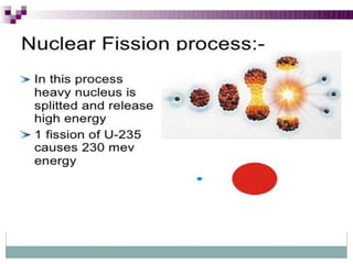
Summer training report
NARORA ATOMIC POWER STATION
Submitted To Submitted By
Mr. Puneet singh RAJKUMARI
(Assistance Professor) B. Tech [E.E] final
Department Of Electrical Engineering year
NARORA ATOMIC POWER STATION
2016
UNDER THE SUPERVISION OF
M R . G A U R A V S H A R M A ( T R A I N I N G S U P E R I N T E N D A N T )
M R . K H A G E S H C H A N D R A ( T R A I N I N G C O O R D I N A T O R )
PROJECT REPORT ON
VOCATIONAL TRAINING
CARRIED OUT AT
Contents
• Introduction
• Layout of NAPS
• Important data about NAPS
• Nuclear reaction
• Nuclear reactor
• Shutdown system
• Electrical system
• Turbo generator
• Generator transformer
• Station unit transformer
• Power supply classification at NAPS
• Diesel generator set
• Power motor generator set
• Switch yard
• Motor control centre
• Specification of Circuit breaker
• protective relay
NAPS station is situated at the bank of river Ganga in
bulandshahr district of u.p . NAPS is a twin unit module of
220 mwe each of pressurized heavy water reactor in this
plant. Natural uranium is used as a fule the heavy water
used for coolant and as moderator. NAPS with northern
grid through five line of 220 kv. NAPS is the 4th atomic
power plant installed in India preceded by Tarapur in
Maharashtra, Rawatbhata in Rajasthan and kalpakkam in
Tamil Nadu.
.Administration building
•Over head water tank
•NDCT
•220 kv switch yard
•Service building
•Reactor building
•Purification building
•Pump house
•Turbine building
• Station training centre
•Waste management plant
• IDCT
1. Transmission line – 5
2. NDCT height – 128 meters
3. NDCT Top Dia – 58 meters
4. NDCT Base Dia – 107 meters
5. NDCT Throat Dia – 53 meters
6. Steam flow – 1314 Ton/hr
7. Steam pressure – 48-40 kg/cm2
8. Coolant tubes – 306
9. Generator power – 220 mwe
10.Grid voltage – 220 kv
Nuclear fission is a nuclear reaction in which the nucleus of an
atom splits into smaller parts (lighter nuclei). The fission
process often produces free neutrons and photons (in the form
of gamma rays), and releases a very large amount of energy
even by the energetic standards of radioactive decay. The heat
produces steam, which drives the turbo-generator & produces
electricity. Natural uranium as a fuel used in this reactor.
The basic nuclear reaction is as follows:
92U235 + 0n1
38Sr94 + 54Xe140 + 2 0n1+ y (Heat Energy)+ γ
(Natural Uranium Oxide)
92U235 +0n1
56Ba141+ 36Kr92 + 3 0n1 + y (Heat Energy) +γ
•Light and heavy water reactors
•Pressurized water reactors (PWR)
•Boiling water reactors (BWR)
•Pressurized heavy water reactors
(PHWR)
NAPS have two diverse & independent shut down system, one of them is
fast acting & other is slow acting.
1. Primary shutdown system
2. Secondary shutdown system
Primary shutdown system
The system is meant to shut down the Reactor whenever any operating
parameter crosses a set limit. The system operates automatically & can
also be operated manually.
The system has 14 rods of cadmium sandwiched in stainless steel as
neutron absorbing element.
Secondary shutdown system
The Secondary Shutdown system comes into action when the primary
shutdown system fails to operate. It is provided as a backup protective
system. It consists of 12 liquid poison tubes which remain empty during
normal course of operation.
The electrical system deals with generation of electrical energy from heat
energy obtained from nuclear reaction and its subsequent transmission and
utilization.
1. Turbo generator
2. Generating transformer
3. Station unit transformer (SUT)
4. Diesel generator set (DG)
5. Power motor generator set (PMG)
1. Active power – 237.7 MW
2. Power factor – 0.90
3. Total power – 264.0 MVA
4. Speed - 3000 rpm
5. Efficiency at full load – 98.6%
Principal of component :-
1. Stator :- stator is the stationary part of the generator . It
is made up of stacked lamination of cold rolled
grain oriented sillicon steel .
2. Rotor:- it is made up chromium –Nickel steel . Field
winding conductor are placed in rotor slots .
3. Slip ring :- slip ring are made of copper ,brush gear is
provided in the generator shaft to inject
excitation current from the static.
Generator excitation system
1. Dc excitation system
2. Ac excitation system
3. Static excitation system
1. Capacity – 265 MVA
2. LV side voltage – 16.5 kv
3. HV side voltage – 235 kv
4. Power factor – 0.9
5. Impedance – 0.14 Pu
6. Coolant – oil natural air forced
The transformer is specified with a HV voltage with a voltage
rate of 220 / 6.6 kv .
The LV voltage of 6.6 kv is the no load voltage of the LV side
on load the voltage
Drop in the SUT will reduce the terminal voltage to 6.6 kv
with the proper selection of tap .
POWER VOLTAGE NATURAL SOURCE
CLASS-1 250 V DC Uninterrupted Battery bank
CLASS-2 415 V AC uninterrupted Power MG set
CLASS-3 415 V AC interruptible DG set
CLASS-4 415 V AC &6.6
KV
interruptible Grid supply & TC
set
1. Rated continuous output -1450 kw
2. Overload capacity for 8 hr – 1650 kw
3. Overload capacity for 2 hr – 1750 kw
The DG set are capable of parallel operation of class -4 power
supply .
NAME RATING
RATING 2600 BHP
SPEED 1000 RPM
NO. OF STOCKES 4 Stoke
POWER FACTOR 0.8 lag
Engine cylinder 16 cylinders
Excitation Static Excitation
pole 6- pole
Excitation voltage 58.5 V
Connection Star , 3 phase
The diesel engine is started by air motor .the air is stored in
air receiver by the
Compressor and this air gives six starter to DG set for cooling
oil and heavy water
Are used.
Power motor generator set
PMG meant for uninterrupted power supply (415 v, 3- phase , 50 Hz)
PMG is start with the help of pony motor with resistance control on bus 1 .
The DC machine acts as a DC generator when the terminal voltage across
the generator equal to the supply voltage (250v , DC).
• circuit breaker
• Isolator
• Lightening Arresters
• Capacitive voltage transformer
• Current transformer
• Carrier communication
• Control room
The motor control centre (MCC ) is an assembly of
panel from where motor starters
For different motors in the station are grouped and
controlled from control room Or field.
•Rated voltage
•Rated current
•Rated frequency
•Rated making capacity
•Rated breaking capacity
•Short time current rating
•Insulation level
•Number of poles
1. Instantaneous over current relay
2. Earth fault relay
3. Definite time over current relay
4. Under voltage relay
5. Instantaneous differential relay
6. Fuse failure relay
7. Directional inverse time over current relay
8. Transformer differential relay
• Selectivity
• Sensitivity
• Speed
• Reliability
Naps

Naps

  • 1.
    Summer training report NARORAATOMIC POWER STATION Submitted To Submitted By Mr. Puneet singh RAJKUMARI (Assistance Professor) B. Tech [E.E] final Department Of Electrical Engineering year
  • 2.
    NARORA ATOMIC POWERSTATION 2016 UNDER THE SUPERVISION OF M R . G A U R A V S H A R M A ( T R A I N I N G S U P E R I N T E N D A N T ) M R . K H A G E S H C H A N D R A ( T R A I N I N G C O O R D I N A T O R ) PROJECT REPORT ON VOCATIONAL TRAINING CARRIED OUT AT
  • 3.
    Contents • Introduction • Layoutof NAPS • Important data about NAPS • Nuclear reaction • Nuclear reactor • Shutdown system • Electrical system • Turbo generator • Generator transformer • Station unit transformer • Power supply classification at NAPS • Diesel generator set • Power motor generator set • Switch yard • Motor control centre • Specification of Circuit breaker • protective relay
  • 4.
    NAPS station issituated at the bank of river Ganga in bulandshahr district of u.p . NAPS is a twin unit module of 220 mwe each of pressurized heavy water reactor in this plant. Natural uranium is used as a fule the heavy water used for coolant and as moderator. NAPS with northern grid through five line of 220 kv. NAPS is the 4th atomic power plant installed in India preceded by Tarapur in Maharashtra, Rawatbhata in Rajasthan and kalpakkam in Tamil Nadu.
  • 5.
    .Administration building •Over headwater tank •NDCT •220 kv switch yard •Service building •Reactor building •Purification building •Pump house •Turbine building • Station training centre •Waste management plant • IDCT
  • 7.
    1. Transmission line– 5 2. NDCT height – 128 meters 3. NDCT Top Dia – 58 meters 4. NDCT Base Dia – 107 meters 5. NDCT Throat Dia – 53 meters 6. Steam flow – 1314 Ton/hr 7. Steam pressure – 48-40 kg/cm2 8. Coolant tubes – 306 9. Generator power – 220 mwe 10.Grid voltage – 220 kv
  • 9.
    Nuclear fission isa nuclear reaction in which the nucleus of an atom splits into smaller parts (lighter nuclei). The fission process often produces free neutrons and photons (in the form of gamma rays), and releases a very large amount of energy even by the energetic standards of radioactive decay. The heat produces steam, which drives the turbo-generator & produces electricity. Natural uranium as a fuel used in this reactor.
  • 10.
    The basic nuclearreaction is as follows: 92U235 + 0n1 38Sr94 + 54Xe140 + 2 0n1+ y (Heat Energy)+ γ (Natural Uranium Oxide) 92U235 +0n1 56Ba141+ 36Kr92 + 3 0n1 + y (Heat Energy) +γ
  • 11.
    •Light and heavywater reactors •Pressurized water reactors (PWR) •Boiling water reactors (BWR) •Pressurized heavy water reactors (PHWR)
  • 16.
    NAPS have twodiverse & independent shut down system, one of them is fast acting & other is slow acting. 1. Primary shutdown system 2. Secondary shutdown system Primary shutdown system The system is meant to shut down the Reactor whenever any operating parameter crosses a set limit. The system operates automatically & can also be operated manually. The system has 14 rods of cadmium sandwiched in stainless steel as neutron absorbing element.
  • 17.
    Secondary shutdown system TheSecondary Shutdown system comes into action when the primary shutdown system fails to operate. It is provided as a backup protective system. It consists of 12 liquid poison tubes which remain empty during normal course of operation.
  • 18.
    The electrical systemdeals with generation of electrical energy from heat energy obtained from nuclear reaction and its subsequent transmission and utilization. 1. Turbo generator 2. Generating transformer 3. Station unit transformer (SUT) 4. Diesel generator set (DG) 5. Power motor generator set (PMG)
  • 19.
    1. Active power– 237.7 MW 2. Power factor – 0.90 3. Total power – 264.0 MVA 4. Speed - 3000 rpm 5. Efficiency at full load – 98.6% Principal of component :- 1. Stator :- stator is the stationary part of the generator . It is made up of stacked lamination of cold rolled grain oriented sillicon steel .
  • 20.
    2. Rotor:- itis made up chromium –Nickel steel . Field winding conductor are placed in rotor slots . 3. Slip ring :- slip ring are made of copper ,brush gear is provided in the generator shaft to inject excitation current from the static. Generator excitation system 1. Dc excitation system 2. Ac excitation system 3. Static excitation system
  • 21.
    1. Capacity –265 MVA 2. LV side voltage – 16.5 kv 3. HV side voltage – 235 kv 4. Power factor – 0.9 5. Impedance – 0.14 Pu 6. Coolant – oil natural air forced
  • 22.
    The transformer isspecified with a HV voltage with a voltage rate of 220 / 6.6 kv . The LV voltage of 6.6 kv is the no load voltage of the LV side on load the voltage Drop in the SUT will reduce the terminal voltage to 6.6 kv with the proper selection of tap .
  • 23.
    POWER VOLTAGE NATURALSOURCE CLASS-1 250 V DC Uninterrupted Battery bank CLASS-2 415 V AC uninterrupted Power MG set CLASS-3 415 V AC interruptible DG set CLASS-4 415 V AC &6.6 KV interruptible Grid supply & TC set
  • 24.
    1. Rated continuousoutput -1450 kw 2. Overload capacity for 8 hr – 1650 kw 3. Overload capacity for 2 hr – 1750 kw The DG set are capable of parallel operation of class -4 power supply .
  • 25.
    NAME RATING RATING 2600BHP SPEED 1000 RPM NO. OF STOCKES 4 Stoke POWER FACTOR 0.8 lag Engine cylinder 16 cylinders Excitation Static Excitation pole 6- pole Excitation voltage 58.5 V Connection Star , 3 phase
  • 26.
    The diesel engineis started by air motor .the air is stored in air receiver by the Compressor and this air gives six starter to DG set for cooling oil and heavy water Are used. Power motor generator set PMG meant for uninterrupted power supply (415 v, 3- phase , 50 Hz) PMG is start with the help of pony motor with resistance control on bus 1 . The DC machine acts as a DC generator when the terminal voltage across the generator equal to the supply voltage (250v , DC).
  • 27.
    • circuit breaker •Isolator • Lightening Arresters • Capacitive voltage transformer • Current transformer • Carrier communication • Control room
  • 28.
    The motor controlcentre (MCC ) is an assembly of panel from where motor starters For different motors in the station are grouped and controlled from control room Or field.
  • 29.
    •Rated voltage •Rated current •Ratedfrequency •Rated making capacity •Rated breaking capacity •Short time current rating •Insulation level •Number of poles
  • 30.
    1. Instantaneous overcurrent relay 2. Earth fault relay 3. Definite time over current relay 4. Under voltage relay 5. Instantaneous differential relay 6. Fuse failure relay 7. Directional inverse time over current relay 8. Transformer differential relay
  • 31.