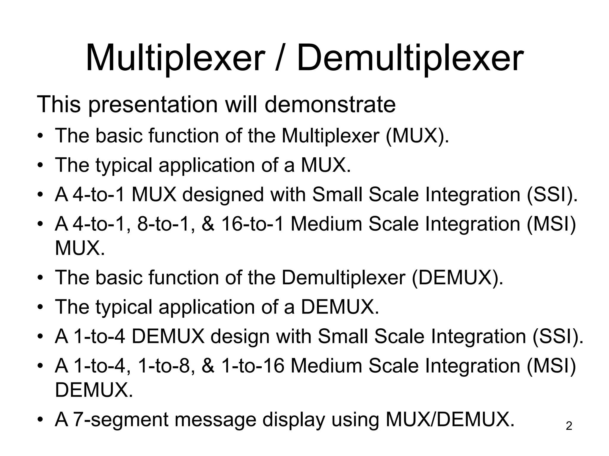
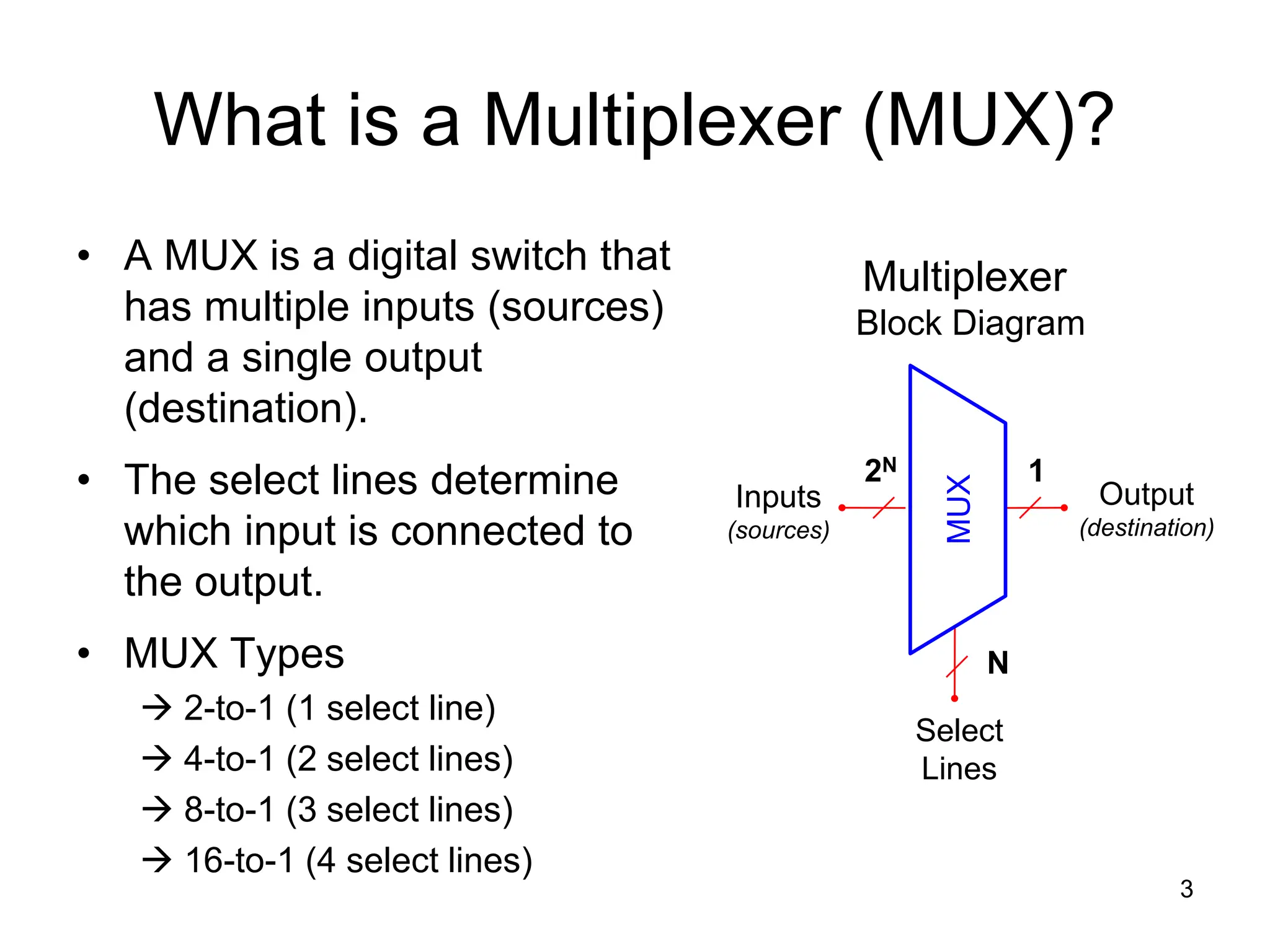
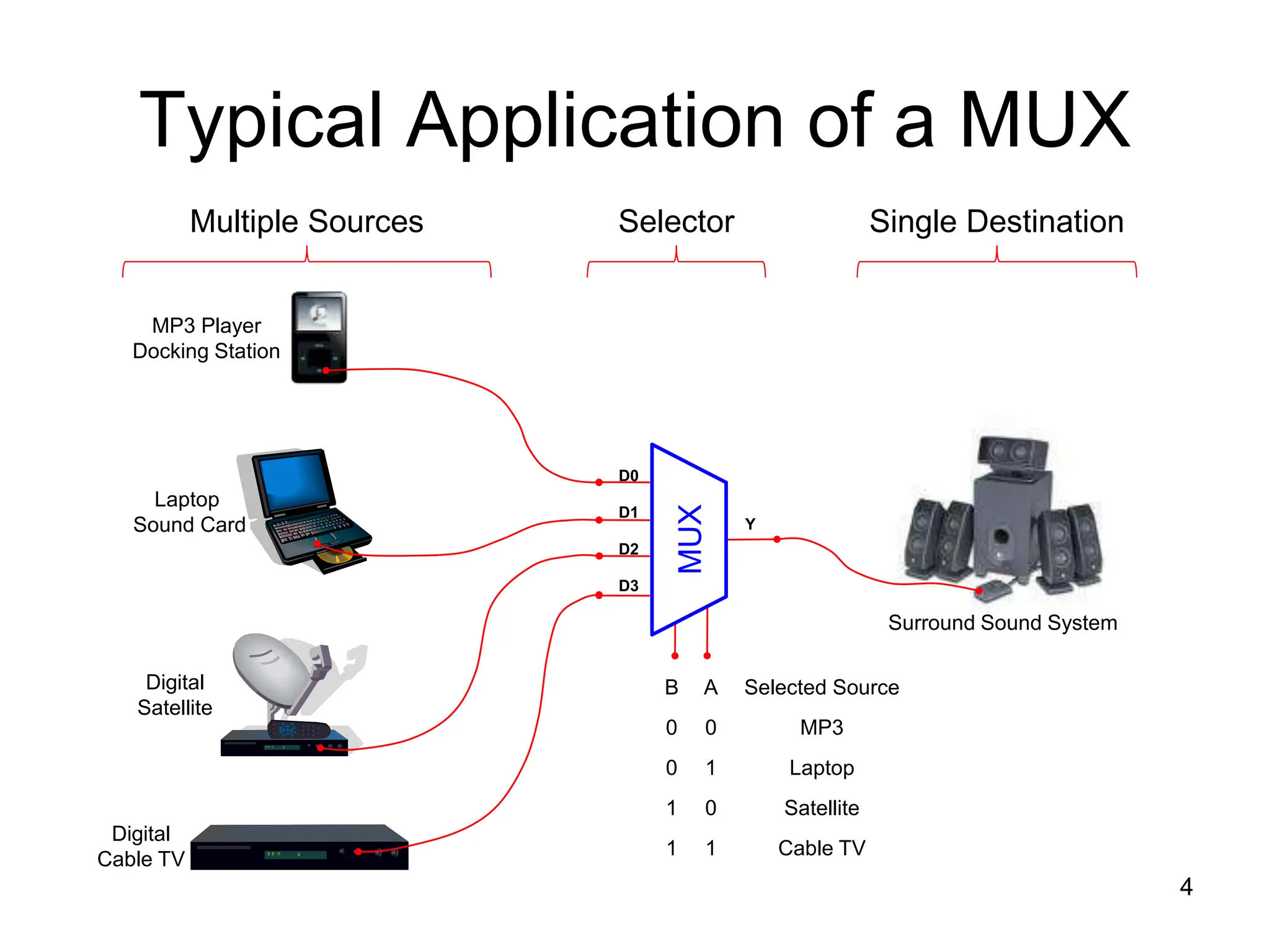
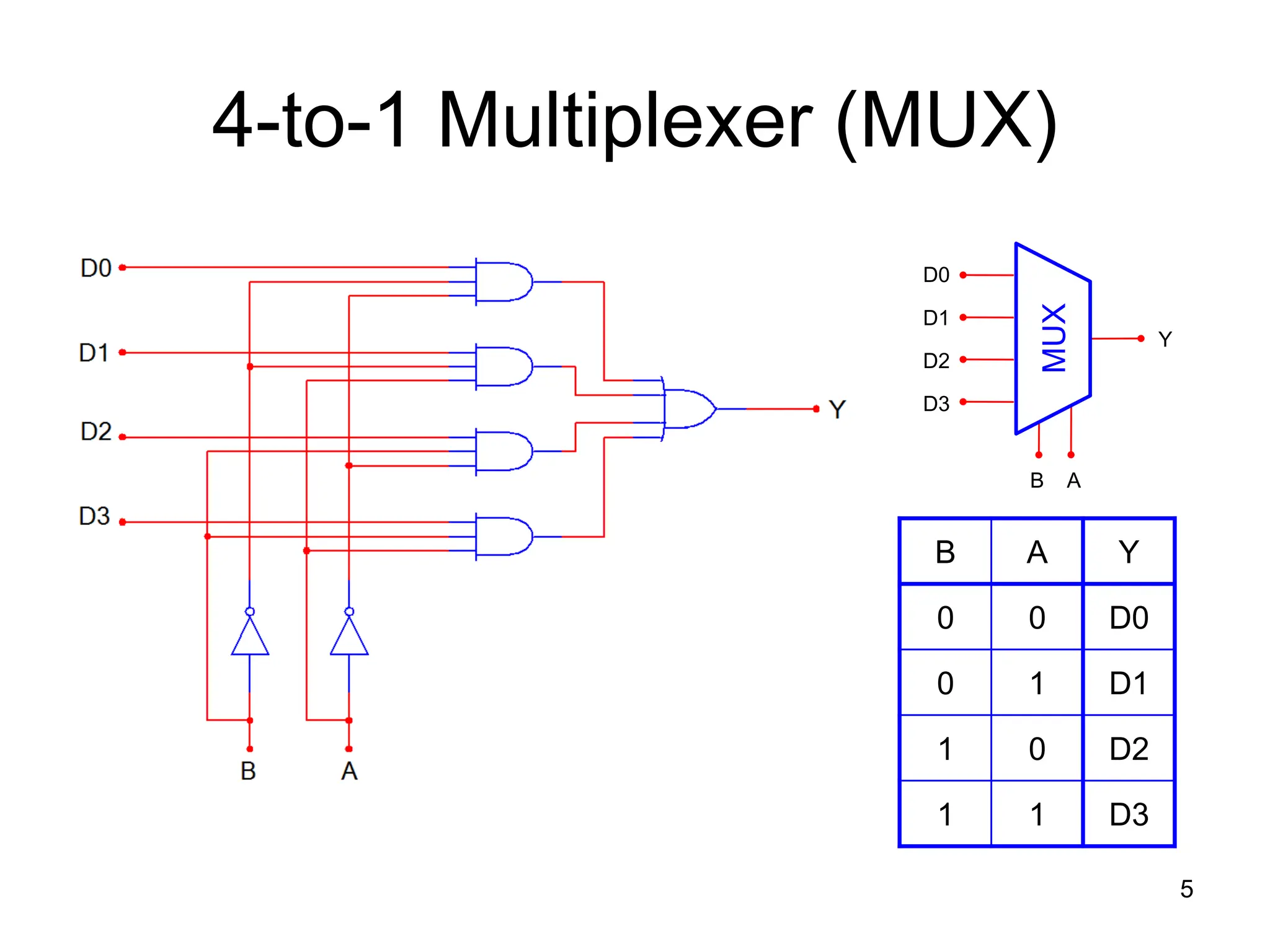
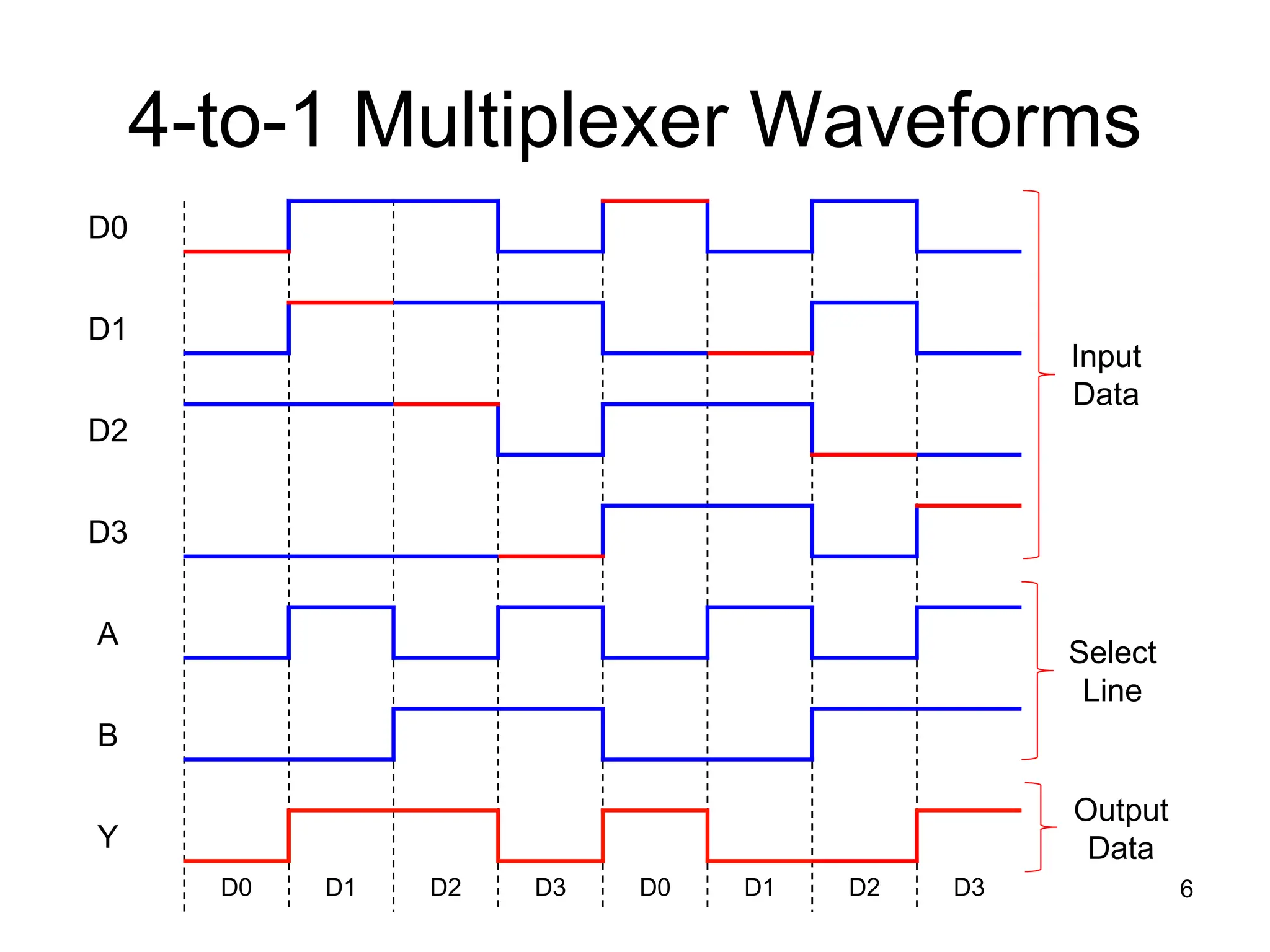
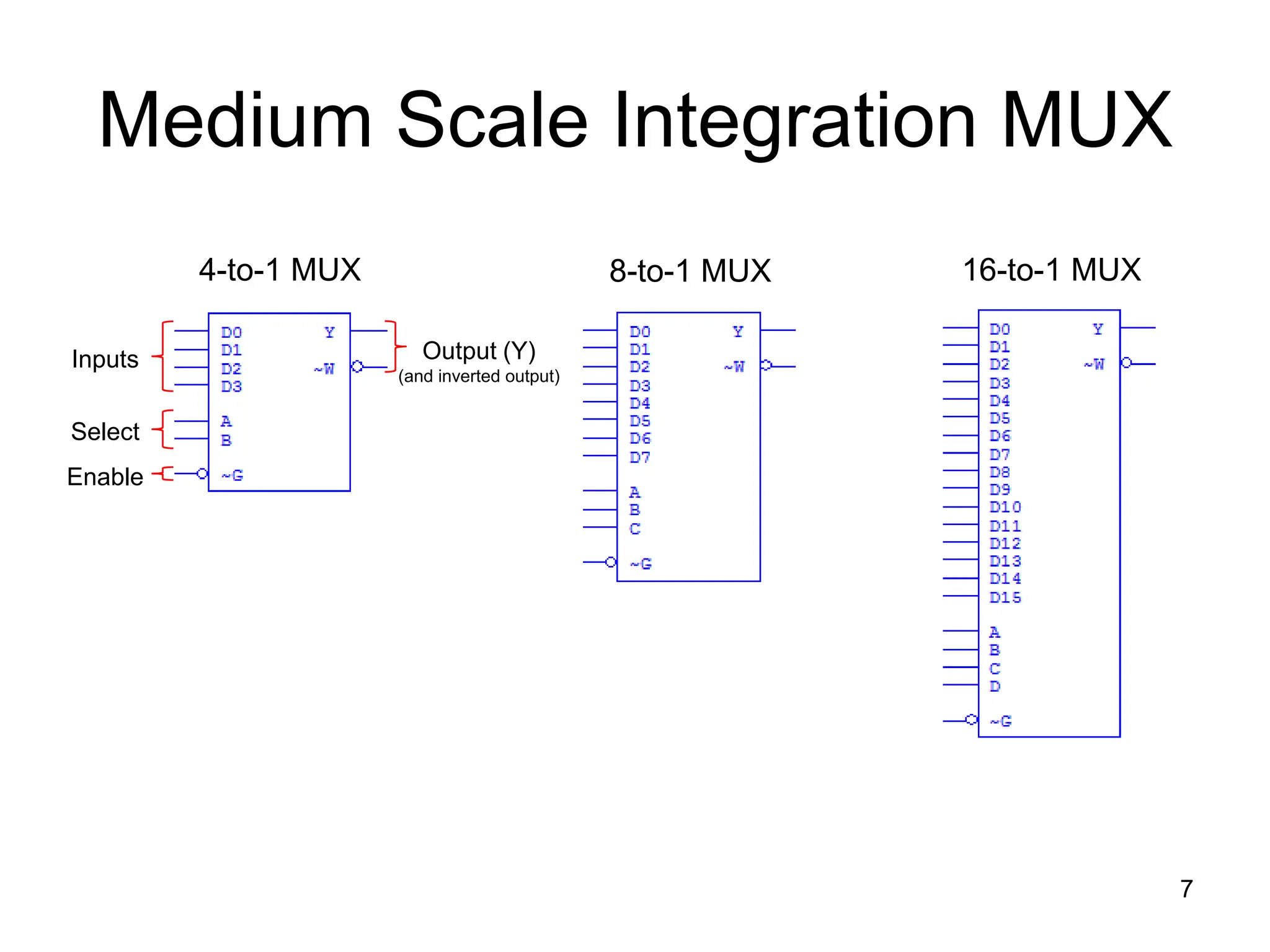
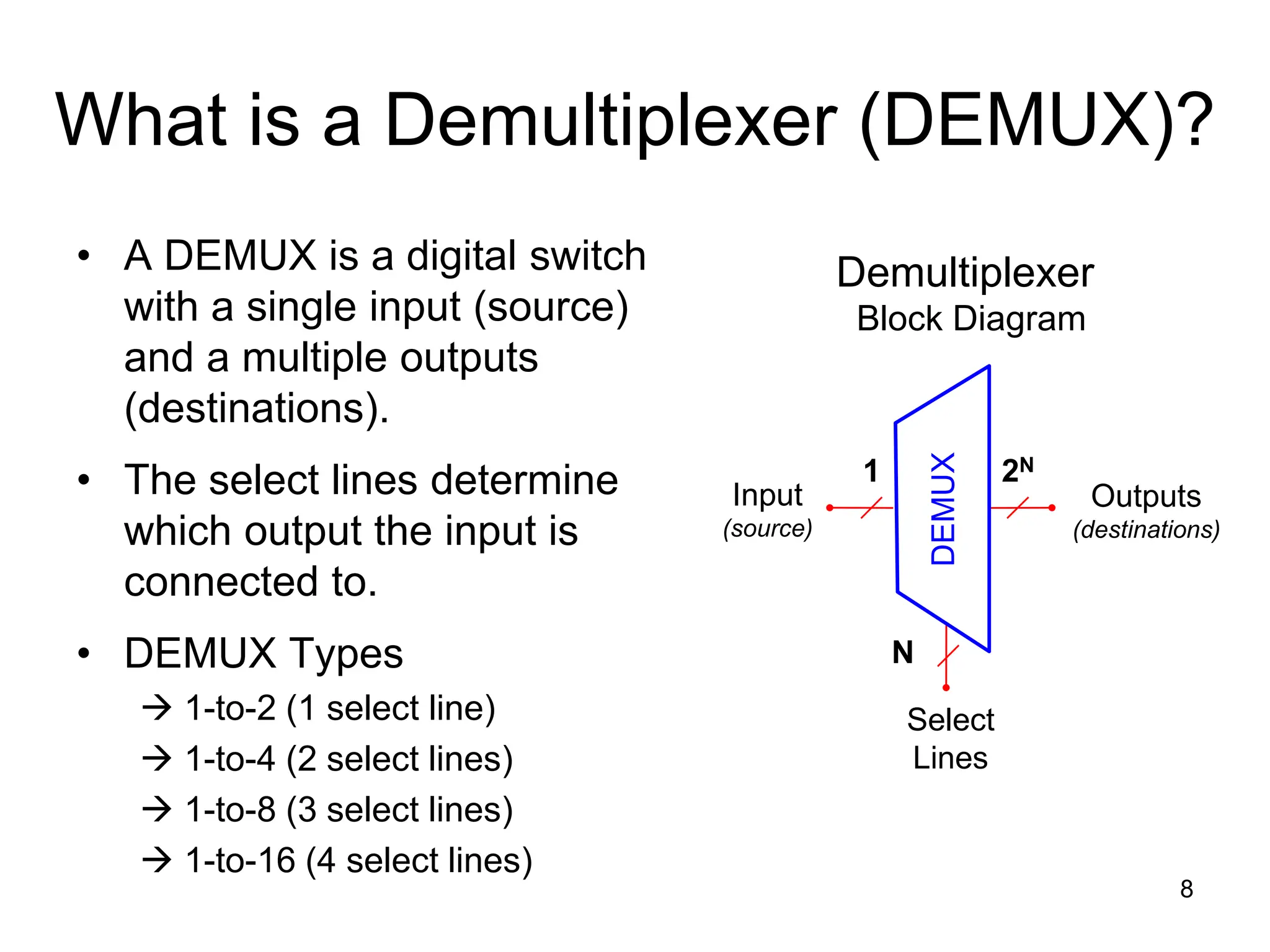
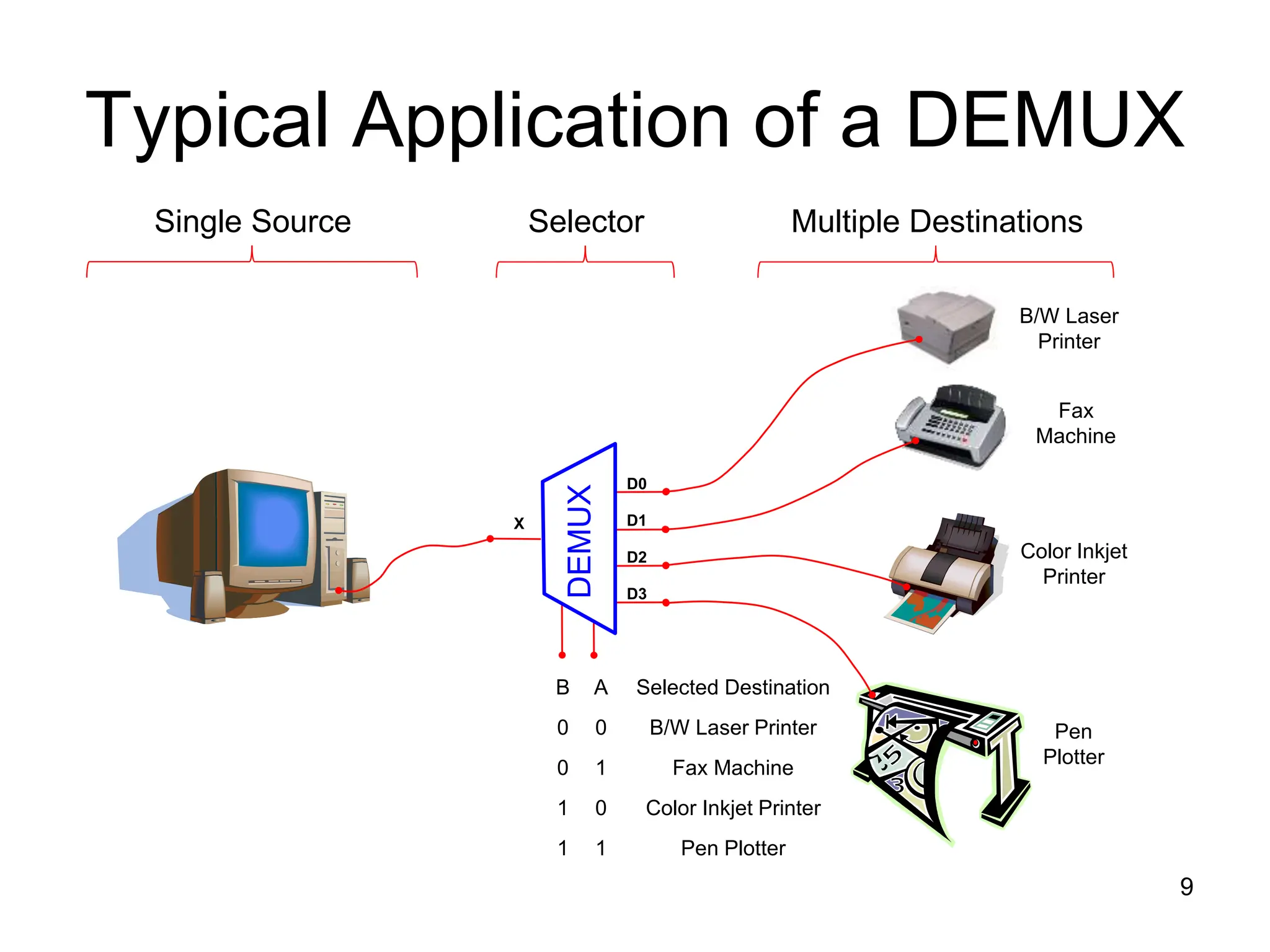
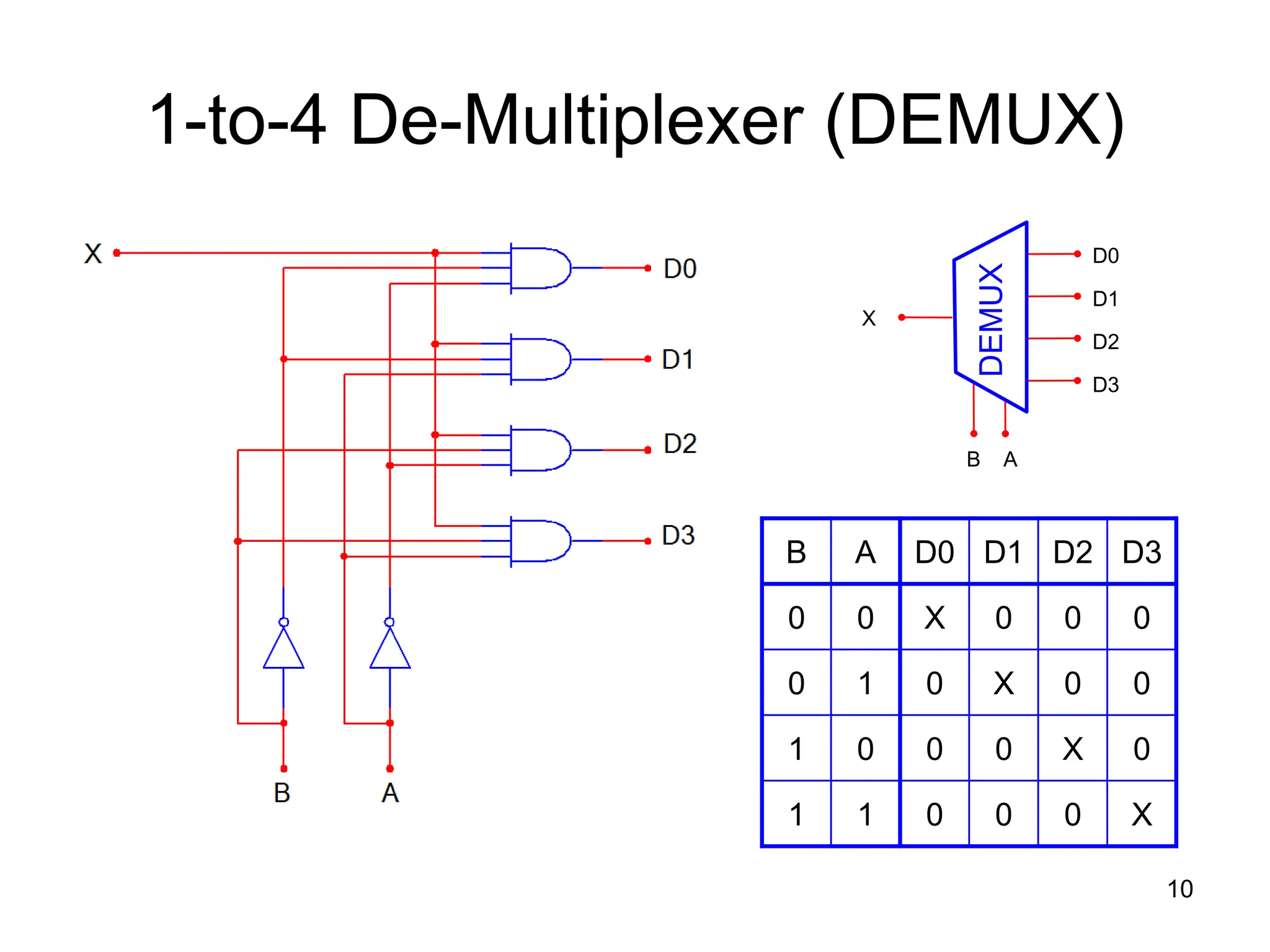
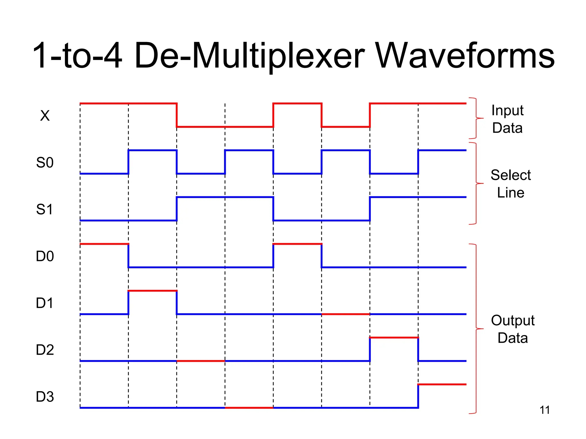
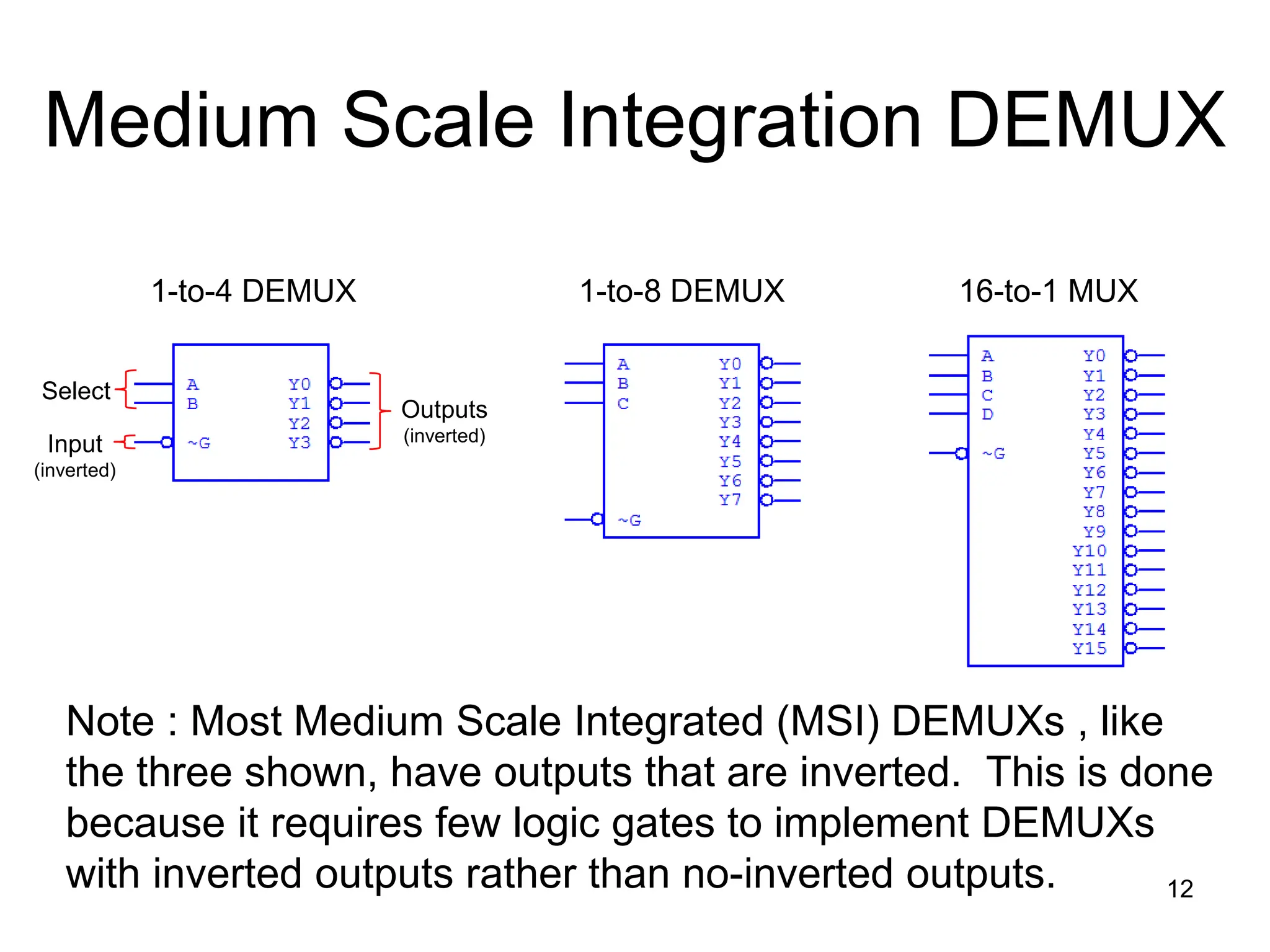
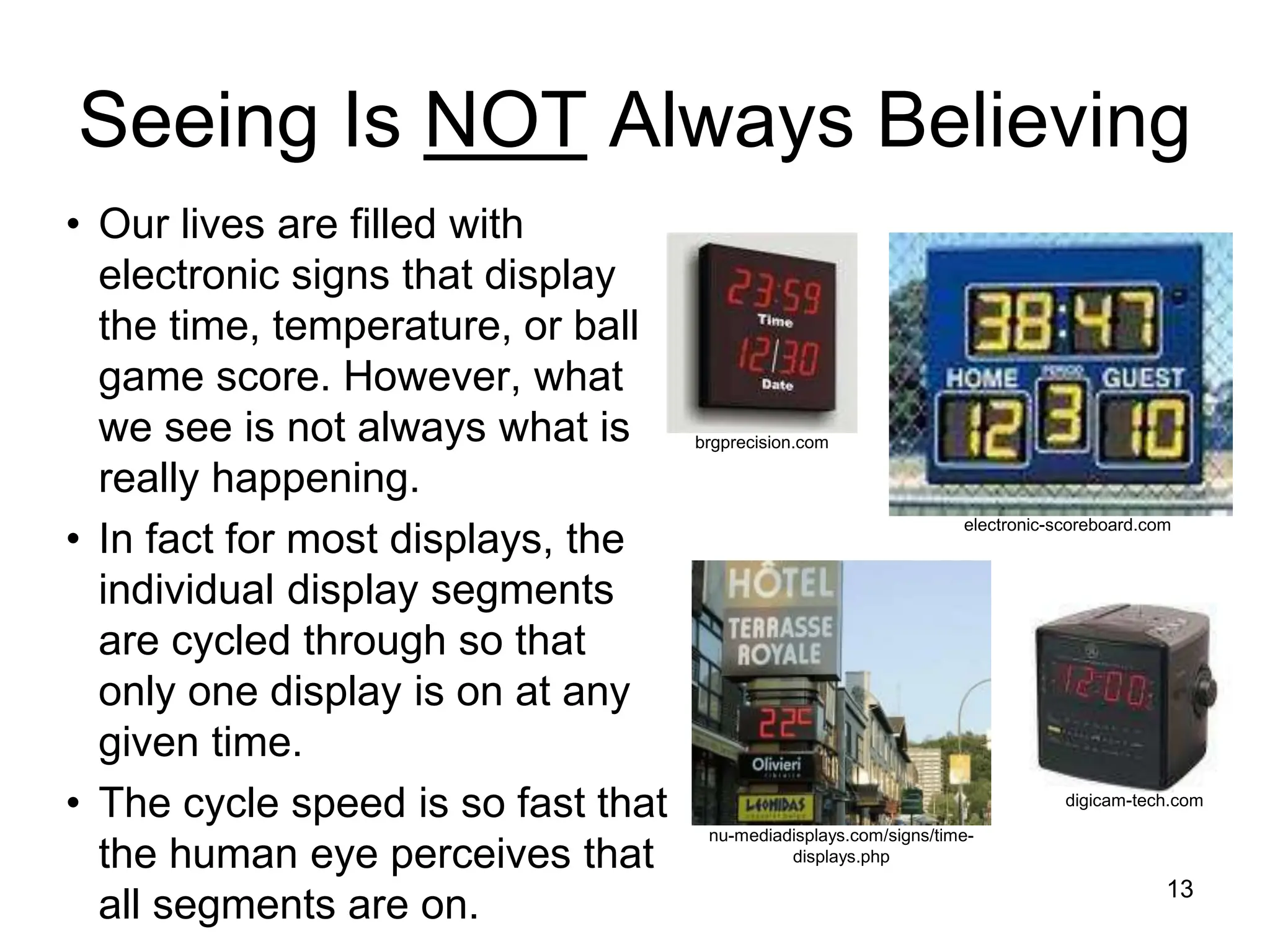
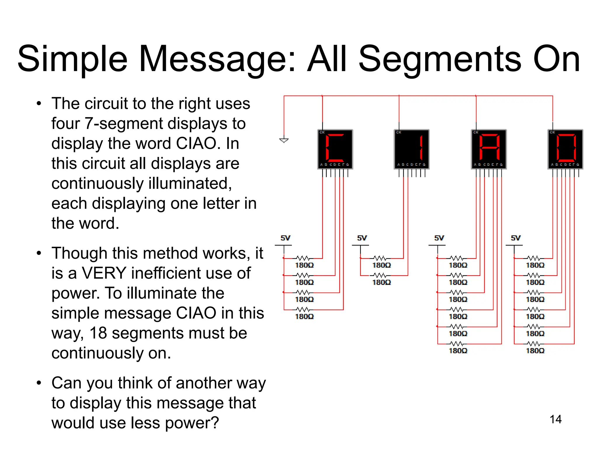
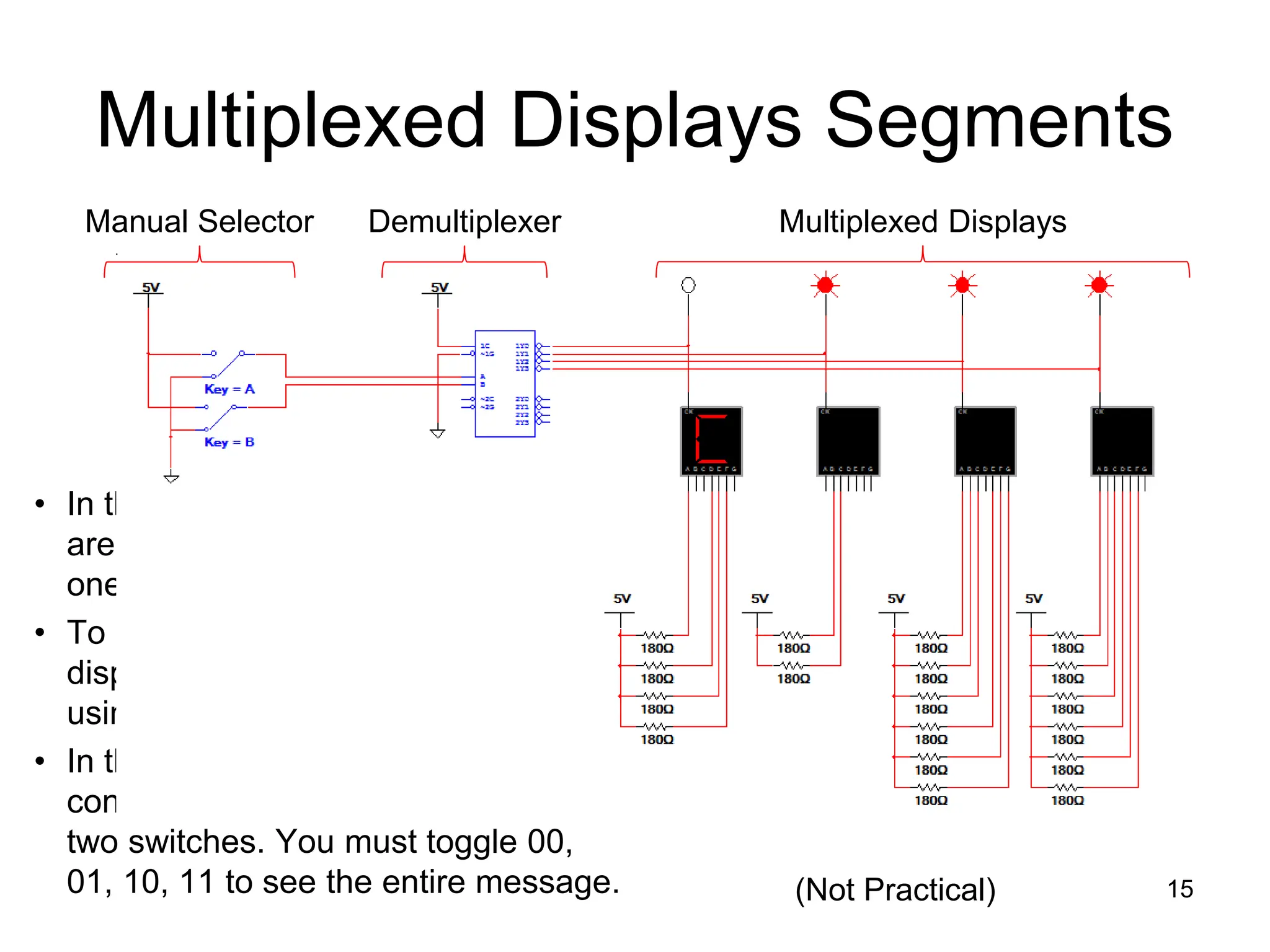
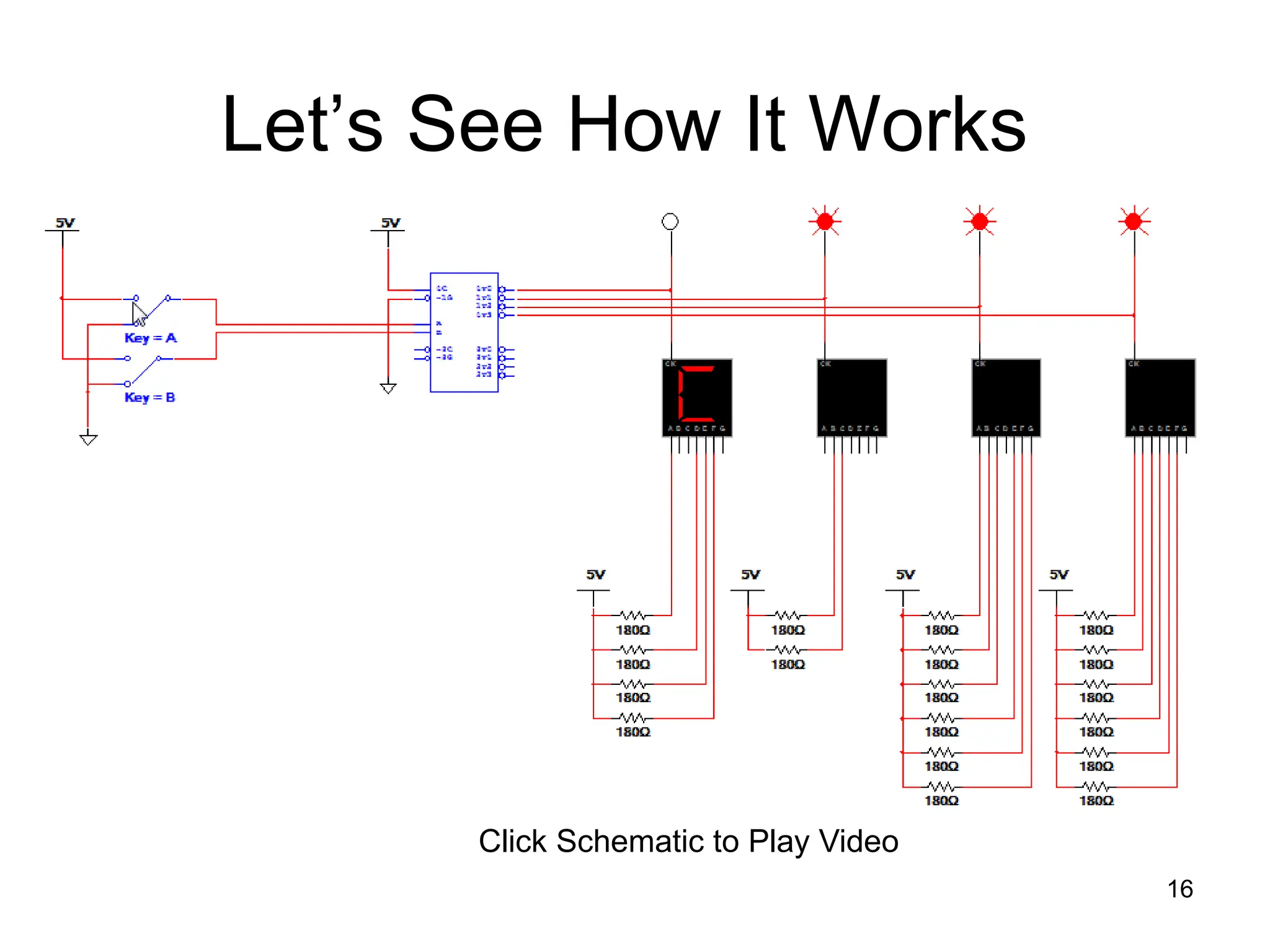
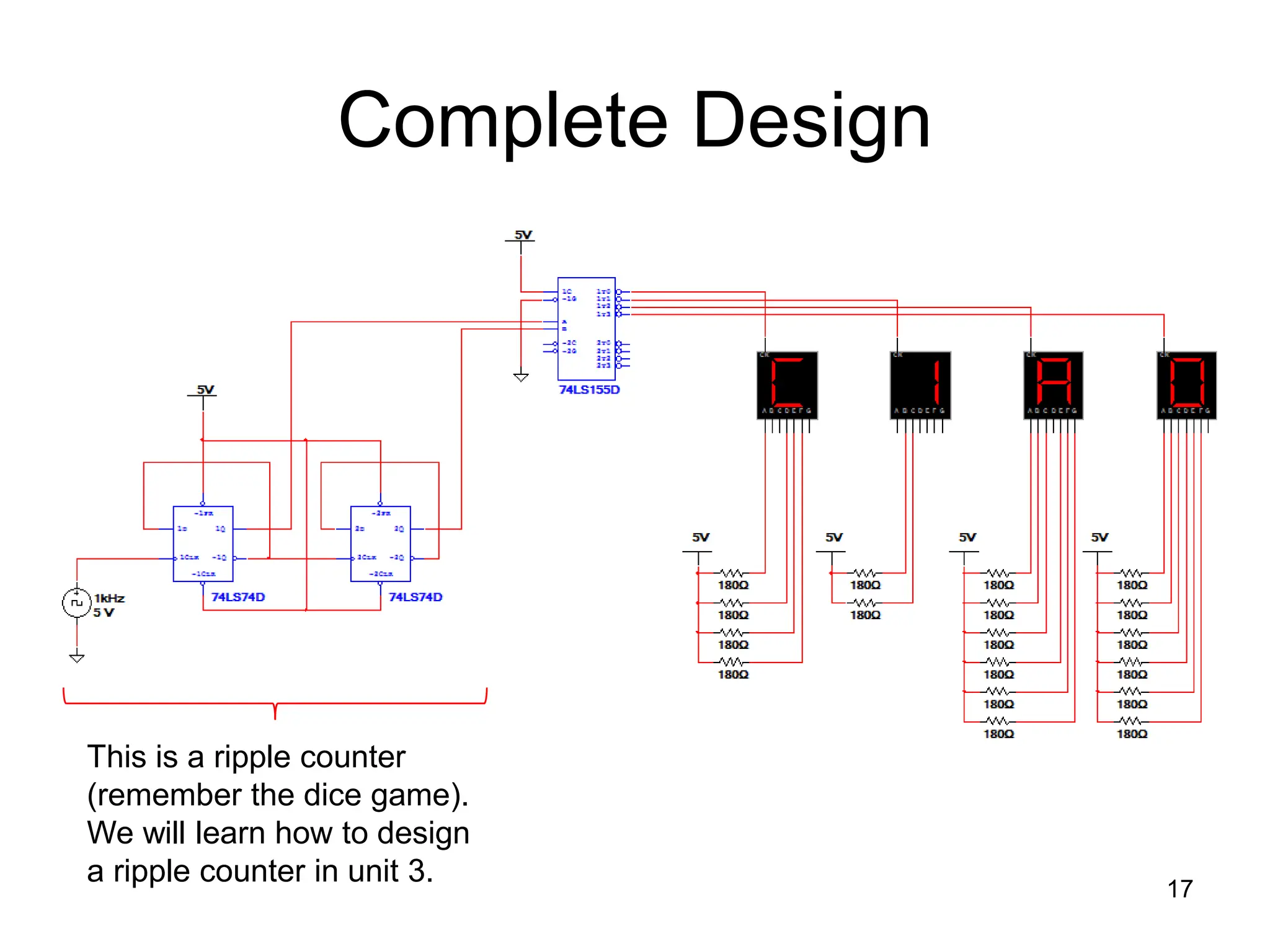
Multiplexer / Demultiplexer
By
Priyanka Ghose
Multiplexer / Demultiplexer
2
This presentation will demonstrate
• The basic function of the Multiplexer (MUX).
• The typical application of a MUX.
• A 4-to-1 MUX designed with Small Scale Integration (SSI).
• A 4-to-1, 8-to-1, & 16-to-1 Medium Scale Integration (MSI)
MUX.
• The basic function of the Demultiplexer (DEMUX).
• The typical application of a DEMUX.
• A 1-to-4 DEMUX design with Small Scale Integration (SSI).
• A 1-to-4, 1-to-8, & 1-to-16 Medium Scale Integration (MSI)
DEMUX.
• A 7-segment message display using MUX/DEMUX.
What is a Multiplexer (MUX)?
• A MUX is a digital switch that
has multiple inputs (sources)
and a single output
(destination).
• The select lines determine
which input is connected to
the output.
• MUX Types
 2-to-1 (1 select line)
 4-to-1 (2 select lines)
 8-to-1 (3 select lines)
 16-to-1 (4 select lines)
3
Multiplexer
Block Diagram
Select
Lines
Inputs
(sources)
Output
(destination)
1
2N
N
MUX
Typical Application of a MUX
4
MP3 Player
Docking Station
Laptop
Sound Card
Digital
Satellite
Digital
Cable TV
Surround Sound System
MUX
D0
D1
D2
D3
Y
B A Selected Source
0 0 MP3
0 1 Laptop
1 0 Satellite
1 1 Cable TV
Multiple Sources Single Destination
Selector
4-to-1 Multiplexer (MUX)
5
B A Y
0 0 D0
0 1 D1
1 0 D2
1 1 D3
MUX
D0
D1
D2
D3
Y
B A
4-to-1 Multiplexer Waveforms
6
D0
D1
D2
D3
A
B
Y
D0 D1 D2 D3 D0 D1 D2 D3
Input
Data
Select
Line
Output
Data
Medium Scale Integration MUX
7
4-to-1 MUX 8-to-1 MUX 16-to-1 MUX
Inputs
Select
Enable
Output (Y)
(and inverted output)
What is a Demultiplexer (DEMUX)?
• A DEMUX is a digital switch
with a single input (source)
and a multiple outputs
(destinations).
• The select lines determine
which output the input is
connected to.
• DEMUX Types
 1-to-2 (1 select line)
 1-to-4 (2 select lines)
 1-to-8 (3 select lines)
 1-to-16 (4 select lines)
8
Demultiplexer
Block Diagram
Select
Lines
Input
(source)
Outputs
(destinations)
2N
1
N
DEMUX
Typical Application of a DEMUX
9
Single Source Multiple Destinations
Selector
D0
D1
D2
D3
X
DEMUX
B A Selected Destination
0 0 B/W Laser Printer
0 1 Fax Machine
1 0 Color Inkjet Printer
1 1 Pen Plotter
B/W Laser
Printer
Color Inkjet
Printer
Pen
Plotter
Fax
Machine
1-to-4 De-Multiplexer (DEMUX)
10
B A D0 D1 D2 D3
0 0 X 0 0 0
0 1 0 X 0 0
1 0 0 0 X 0
1 1 0 0 0 X
D0
D1
D2
D3
X
B A
DEMUX
1-to-4 De-Multiplexer Waveforms
11
X
S0
S1
D0
D1
D2
D3
Output
Data
Select
Line
Input
Data
Medium Scale Integration DEMUX
12
1-to-4 DEMUX 1-to-8 DEMUX 16-to-1 MUX
Select
Input
(inverted)
Outputs
(inverted)
Note : Most Medium Scale Integrated (MSI) DEMUXs , like
the three shown, have outputs that are inverted. This is done
because it requires few logic gates to implement DEMUXs
with inverted outputs rather than no-inverted outputs.
Seeing Is NOT Always Believing
• Our lives are filled with
electronic signs that display
the time, temperature, or ball
game score. However, what
we see is not always what is
really happening.
• In fact for most displays, the
individual display segments
are cycled through so that
only one display is on at any
given time.
• The cycle speed is so fast that
the human eye perceives that
all segments are on. 13
digicam-tech.com
brgprecision.com
electronic-scoreboard.com
nu-mediadisplays.com/signs/time-
displays.php
Simple Message: All Segments On
14
• The circuit to the right uses
four 7-segment displays to
display the word CIAO. In
this circuit all displays are
continuously illuminated,
each displaying one letter in
the word.
• Though this method works, it
is a VERY inefficient use of
power. To illuminate the
simple message CIAO in this
way, 18 segments must be
continuously on.
• Can you think of another way
to display this message that
would use less power? 14
Multiplexed Displays Segments
• In this circuit the display segments
are multiplexed, meaning that only
one display is on at a time.
• To display the entire word, the
displays must be de-multiplexed
using a 1-to-4 DEMUX.
• In this example the select lines that
control the DEMUX are connected to
two switches. You must toggle 00,
01, 10, 11 to see the entire message. 15
Manual Selector Multiplexed Displays
Demultiplexer
(Not Practical)
Let’s See How It Works
16
Click Schematic to Play Video
Complete Design
17
This is a ripple counter
(remember the dice game).
We will learn how to design
a ripple counter in unit 3.

Multiplexer_ and_ Demultiplexer. .ppt.

  • 1.
  • 2.
    Multiplexer / Demultiplexer 2 Thispresentation will demonstrate • The basic function of the Multiplexer (MUX). • The typical application of a MUX. • A 4-to-1 MUX designed with Small Scale Integration (SSI). • A 4-to-1, 8-to-1, & 16-to-1 Medium Scale Integration (MSI) MUX. • The basic function of the Demultiplexer (DEMUX). • The typical application of a DEMUX. • A 1-to-4 DEMUX design with Small Scale Integration (SSI). • A 1-to-4, 1-to-8, & 1-to-16 Medium Scale Integration (MSI) DEMUX. • A 7-segment message display using MUX/DEMUX.
  • 3.
    What is aMultiplexer (MUX)? • A MUX is a digital switch that has multiple inputs (sources) and a single output (destination). • The select lines determine which input is connected to the output. • MUX Types  2-to-1 (1 select line)  4-to-1 (2 select lines)  8-to-1 (3 select lines)  16-to-1 (4 select lines) 3 Multiplexer Block Diagram Select Lines Inputs (sources) Output (destination) 1 2N N MUX
  • 4.
    Typical Application ofa MUX 4 MP3 Player Docking Station Laptop Sound Card Digital Satellite Digital Cable TV Surround Sound System MUX D0 D1 D2 D3 Y B A Selected Source 0 0 MP3 0 1 Laptop 1 0 Satellite 1 1 Cable TV Multiple Sources Single Destination Selector
  • 5.
    4-to-1 Multiplexer (MUX) 5 BA Y 0 0 D0 0 1 D1 1 0 D2 1 1 D3 MUX D0 D1 D2 D3 Y B A
  • 6.
    4-to-1 Multiplexer Waveforms 6 D0 D1 D2 D3 A B Y D0D1 D2 D3 D0 D1 D2 D3 Input Data Select Line Output Data
  • 7.
    Medium Scale IntegrationMUX 7 4-to-1 MUX 8-to-1 MUX 16-to-1 MUX Inputs Select Enable Output (Y) (and inverted output)
  • 8.
    What is aDemultiplexer (DEMUX)? • A DEMUX is a digital switch with a single input (source) and a multiple outputs (destinations). • The select lines determine which output the input is connected to. • DEMUX Types  1-to-2 (1 select line)  1-to-4 (2 select lines)  1-to-8 (3 select lines)  1-to-16 (4 select lines) 8 Demultiplexer Block Diagram Select Lines Input (source) Outputs (destinations) 2N 1 N DEMUX
  • 9.
    Typical Application ofa DEMUX 9 Single Source Multiple Destinations Selector D0 D1 D2 D3 X DEMUX B A Selected Destination 0 0 B/W Laser Printer 0 1 Fax Machine 1 0 Color Inkjet Printer 1 1 Pen Plotter B/W Laser Printer Color Inkjet Printer Pen Plotter Fax Machine
  • 10.
    1-to-4 De-Multiplexer (DEMUX) 10 BA D0 D1 D2 D3 0 0 X 0 0 0 0 1 0 X 0 0 1 0 0 0 X 0 1 1 0 0 0 X D0 D1 D2 D3 X B A DEMUX
  • 11.
  • 12.
    Medium Scale IntegrationDEMUX 12 1-to-4 DEMUX 1-to-8 DEMUX 16-to-1 MUX Select Input (inverted) Outputs (inverted) Note : Most Medium Scale Integrated (MSI) DEMUXs , like the three shown, have outputs that are inverted. This is done because it requires few logic gates to implement DEMUXs with inverted outputs rather than no-inverted outputs.
  • 13.
    Seeing Is NOTAlways Believing • Our lives are filled with electronic signs that display the time, temperature, or ball game score. However, what we see is not always what is really happening. • In fact for most displays, the individual display segments are cycled through so that only one display is on at any given time. • The cycle speed is so fast that the human eye perceives that all segments are on. 13 digicam-tech.com brgprecision.com electronic-scoreboard.com nu-mediadisplays.com/signs/time- displays.php
  • 14.
    Simple Message: AllSegments On 14 • The circuit to the right uses four 7-segment displays to display the word CIAO. In this circuit all displays are continuously illuminated, each displaying one letter in the word. • Though this method works, it is a VERY inefficient use of power. To illuminate the simple message CIAO in this way, 18 segments must be continuously on. • Can you think of another way to display this message that would use less power? 14
  • 15.
    Multiplexed Displays Segments •In this circuit the display segments are multiplexed, meaning that only one display is on at a time. • To display the entire word, the displays must be de-multiplexed using a 1-to-4 DEMUX. • In this example the select lines that control the DEMUX are connected to two switches. You must toggle 00, 01, 10, 11 to see the entire message. 15 Manual Selector Multiplexed Displays Demultiplexer (Not Practical)
  • 16.
    Let’s See HowIt Works 16 Click Schematic to Play Video
  • 17.
    Complete Design 17 This isa ripple counter (remember the dice game). We will learn how to design a ripple counter in unit 3.

Editor's Notes

  • #2 Digital Electronics Lesson 2.4 – Specific Combo Circuits & Misc Topics
  • #3 Introductory Slide / Overview of Presentation
  • #5 This slide shows a typical application of a multiplexer (in this case a 4-to-1 MUX). Have the students share other common applications of MUXs. http://images.tigerdirect.ca/skuimages/large/Logitech-X-540-L23-7250-mai.jpg
  • #6 SSI logic diagram, block diagram, and truth table for a 4-to-1 MUX
  • #7 Waveform diagram for a 4-to-1 MUX. The input data signals (D0-D3) are colored RED to indicate when its is connected to the output Y. Note: There is no significance to the values of the four input data signals; they are intended solely to demonstrate that the select lines (A & B) will select what input data signal will be connected to the output.
  • #8 Block diagrams for 4-to-1, 8-to-1, and 16-to-1 MSI Multiplexers.
  • #9 This slide explains the function of a demultiplexer.
  • #10 This slide shows a typical application of a demultiplexer (in this case a 1-to-4 DEMUX). Ask students to share other common applications of DEMUXs.
  • #11 SSI logic diagram, block diagram, and truth table for a 1-to-4 De-MUX
  • #12 Waveform diagrams for a 1-to-4 De-MUX. The output signals (D0-D3) are colored RED to indicate when its is connected to the input X. Note: There is no significance to the value of the input data signal; it is intended solely to demonstrate that the select lines (A & B) will determine what output signal is connected to the input.
  • #13 Block diagrams for 1-to-4, 1-to-8, and 1-to-16 MSI Demultiplexers.
  • #14 This slide provides examples of various electronics signs and explains that display segments are not all on simultaneously. www.brgprecision.com www.digicam-tech.com www.electronic-scoreboard.com http://www.nu-mediadisplays.com/signs/time-displays.php
  • #15 This slide shows how a simple message can be displayed using seven-segments displays. The drawback to this method is that all displays are on simultaneously. To display CIAO, 18 segments must be on, all drawing current and using power. Ask students to consider ways that they could display the message WITHOUT running all displays simultaneously.
  • #16 This slide shows how to de-multiplex four multiplexed seven segment displays. The advantage of this method is that only one display is on at any time. To display CIAO, at most 6 segments will be on at any time (for letters A & O).
  • #17 Click the schematic to play the video of the de-multiplexing of the multiplexed displays.
  • #18 This schematic illustrates the complete design. In this circuit a 2-bit ripple counter has replaced the manual switches. Note: This design does work, but if you try to simulate it, the displays will not look correct. This has nothing to do with the design, but is caused by the inability of the simulator to keep up with the clock.