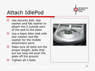
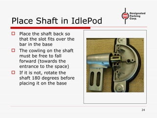
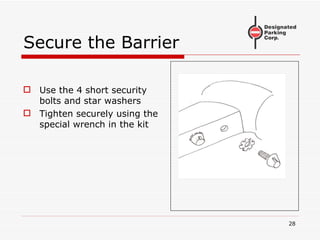
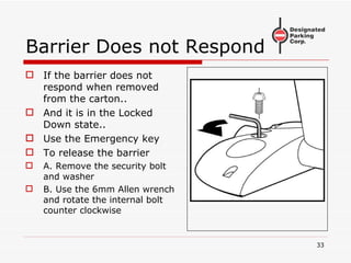
MySpot 200 Installation Procedure (Concrete) 19JULY2007
Locating the MySpot 200 The unit is placed so that, when the car is parked the barrier is ahead of the rear wheels  but does not interfere with the access to the front doors.
Install in Middle Only install the unit in the  middle  of the space
Space Requirements Surface must be flat No standing water No high points
Inspect the Carton A: PowerPod (includes the electronics and the mechanism) B: IdlePod C: Barrier D: (2) remote controls E:  Parts kit F:  Drilling Template
Where to Place the Unit Place the template “TT” as shown
Direction of Template The template must be perpendicular to the edge of the parking space Note the direction of the arrow on the template
Drill Pilot Holes Use a small (6mm, ¼”) drill to mark the 7 holes by drilling through the template into the surface Do not drill directly with the larger drill Remove template Verify that all 7 holes are clearly visible
Concrete or Asphalt? The procedure is different for concrete and for asphalt surfaces. If the surface is asphalt, close this manual and select the “Asphalt installation” manual
Concrete Anchors 7 anchors are included Each includes a special M6 bolt and washer They require a 65mm hole depth They require a hole diameter of 10mm (3/8”)
Concrete: Drill 7 holes Use a 10mm (3/8”) masonry drill Drill  precisely  where the 7 small holes were marked Drill to a depth of 65mm (2.5”) or more Blow holes clean when done
Insert Anchors Push anchors into holes until the head is flush with ground Use M6 wrench to tighten Allen bolt moderately Do not remove bolts yet
Clean Surface Broom sweep area
Remove Screws Removed the bolts and washers from the 7 anchors
Separate Plates from Pods Remove 4 security bolts from PowerPod Remove 2 security bolts from IdlePod Separate the pods from the plates
Attach Plates Use large washers and bolts from anchors (7 sets) Secure plates to ground Do not tighten yet
Check alignment Bend or cut template as shown Place template between plates Adjust plates until aligned parallel to edges of template Verify that there is less than 4mm (1/8”) gap between template and plates
Tighten Screws Once the alignment has been confirmed, tighten the 7 bolts of the anchors If any bolt will not tighten (anchor slips), remove anchor, use some filler and reapply anchor It is essential that all 7 anchors share the load
Attach PowerPod Use the 4 security bolts and washers that came with the IdlePod assembly to secure the pod to the plate If the wrong bolts are used (too long), they will push the plates out of the ground Tighten the 4 bolts securely
Disassemble IdlePod The IdlePod needs to be attached to its plate using 3 bolts To access the 3 rd  bolt, the cover needs to be removed Use the security wrench to remove the 3 bolts
Remove Cover Lift the cover of the IdlePod Lift the shaft The 3 rd  hole may be protected by a plastic insert Remove the insert by pushing it from the top
Prepare IdlePod Plate Place 2 adaptors over the 2 outside holes in the plate If these adaptors are not in your kit, proceed without them
Attach IdlePod Use security bolt, star washer and flat washer to attach the 2 outside ears of the pod to the plate Use a black Allen bolt with star washer and flat washer for the middle attachment point Make sure all bolts are the proper length; bolts that are too long will push the plate off the ground Tighten all 3 bolts
Place Shaft in IdlePod Place the shaft back so that the slot fits over the bar in the base The cowling on the shaft must be free to fall forward (towards the entrance to the space) If it is not, rotate the shaft 180 degrees before placing it on the base
Close Cover of IdlePod Place the cover over the IdlePod Make sure it is seated correctly Secure in place using 3 security bolts with star washers
WARNING Failure to use the internal bolt for mounting the IdlePod to the plate will cause the IdlePod ears to break off and void the warranty
Install the Barrier Slide the barrier over the cowlings of the 2 pods as shown The barrier should be kept parallel to the ground as it is being installed Only minimal force is required If excessive force is required, check the alignment of the pods
Secure the Barrier Use the 4 short security bolts and star washers Tighten securely using the special wrench in the kit
Ready for Test The installation is now complete. The next steps cover the test procedure
The Remotes 2 Remote controls are included in the kit Each remote can control up to 9 separate barriers The barrier in the kit was factory programmed to accept the #2 button on each of the 2 remotes
Terminology Please study the sketch on the right Shown are 4 states of the barrier
Locked Up State This is the normal “blocking” state Applying moderate force to the barrier in either direction will not move the barrier However, if the force exceeds 30 Kg (65 lbs), the barrier will yield When the excessive force is removed, the barrier will return to the Locked Up state.
Barrier Does not Respond If the barrier does not respond when removed from the carton.. And it is in the Locked Down state.. Use the Emergency key To release the barrier A. Remove the security bolt and washer B. Use the 6mm Allen wrench and rotate the internal bolt counter clockwise
UnLocked State Press the #2 button on the Remote. The barrier will fall Its new position is the Un Locked state In this state, the barrier can be raised by hand with no resistance If raised all the way, it will lock in the Locked Up position If the barrier was previously manually raised, when the command drops the barrier to the UnLocked state, the internal motor can be heard running an extra cycle.  This is normal
Locked Down State When a wheel of the car drives over the barrier, the barrier is pushed to the ground That is the Overtravel state When the wheel leaves the barrier, the barrier returns to the Locked Down state The only way to exit the locked down state is via a remote command
Testing, continued If the barrier is in the Unlocked state… … Step on the barrier You need to apply 100 Kg (220 lbs) to force the barrier to the ground Jump if your weight is less than that… The barrier will hit the ground When you step off, it will rise somewhat to the Locked Down state
Testing, Last Step Step on the barrier a second time The barrier needs to be driven on twice, like a car getting in and out, to prevent accidental raising of the barrier under a parked car Push the #2 button on the remote The barrier will rise to the Locked Up position
Troubleshooting If you run into a problem when testing the unit Look up the troubleshooting chart The chart is printed at the end of the installation manual Or it is available on the web site
Thank You Please do not hesitate to contact our hotline +1 973 669 8214 ext 1  during business hours 09:00 to 17:00 Eastern Standard Time (GMT -5:00)

Ms200 Install Concrete

  • 1.
    MySpot 200 InstallationProcedure (Concrete) 19JULY2007
  • 2.
    Locating the MySpot200 The unit is placed so that, when the car is parked the barrier is ahead of the rear wheels but does not interfere with the access to the front doors.
  • 3.
    Install in MiddleOnly install the unit in the middle of the space
  • 4.
    Space Requirements Surfacemust be flat No standing water No high points
  • 5.
    Inspect the CartonA: PowerPod (includes the electronics and the mechanism) B: IdlePod C: Barrier D: (2) remote controls E: Parts kit F: Drilling Template
  • 6.
    Where to Placethe Unit Place the template “TT” as shown
  • 7.
    Direction of TemplateThe template must be perpendicular to the edge of the parking space Note the direction of the arrow on the template
  • 8.
    Drill Pilot HolesUse a small (6mm, ¼”) drill to mark the 7 holes by drilling through the template into the surface Do not drill directly with the larger drill Remove template Verify that all 7 holes are clearly visible
  • 9.
    Concrete or Asphalt?The procedure is different for concrete and for asphalt surfaces. If the surface is asphalt, close this manual and select the “Asphalt installation” manual
  • 10.
    Concrete Anchors 7anchors are included Each includes a special M6 bolt and washer They require a 65mm hole depth They require a hole diameter of 10mm (3/8”)
  • 11.
    Concrete: Drill 7holes Use a 10mm (3/8”) masonry drill Drill precisely where the 7 small holes were marked Drill to a depth of 65mm (2.5”) or more Blow holes clean when done
  • 12.
    Insert Anchors Pushanchors into holes until the head is flush with ground Use M6 wrench to tighten Allen bolt moderately Do not remove bolts yet
  • 13.
  • 14.
    Remove Screws Removedthe bolts and washers from the 7 anchors
  • 15.
    Separate Plates fromPods Remove 4 security bolts from PowerPod Remove 2 security bolts from IdlePod Separate the pods from the plates
  • 16.
    Attach Plates Uselarge washers and bolts from anchors (7 sets) Secure plates to ground Do not tighten yet
  • 17.
    Check alignment Bendor cut template as shown Place template between plates Adjust plates until aligned parallel to edges of template Verify that there is less than 4mm (1/8”) gap between template and plates
  • 18.
    Tighten Screws Oncethe alignment has been confirmed, tighten the 7 bolts of the anchors If any bolt will not tighten (anchor slips), remove anchor, use some filler and reapply anchor It is essential that all 7 anchors share the load
  • 19.
    Attach PowerPod Usethe 4 security bolts and washers that came with the IdlePod assembly to secure the pod to the plate If the wrong bolts are used (too long), they will push the plates out of the ground Tighten the 4 bolts securely
  • 20.
    Disassemble IdlePod TheIdlePod needs to be attached to its plate using 3 bolts To access the 3 rd bolt, the cover needs to be removed Use the security wrench to remove the 3 bolts
  • 21.
    Remove Cover Liftthe cover of the IdlePod Lift the shaft The 3 rd hole may be protected by a plastic insert Remove the insert by pushing it from the top
  • 22.
    Prepare IdlePod PlatePlace 2 adaptors over the 2 outside holes in the plate If these adaptors are not in your kit, proceed without them
  • 23.
    Attach IdlePod Usesecurity bolt, star washer and flat washer to attach the 2 outside ears of the pod to the plate Use a black Allen bolt with star washer and flat washer for the middle attachment point Make sure all bolts are the proper length; bolts that are too long will push the plate off the ground Tighten all 3 bolts
  • 24.
    Place Shaft inIdlePod Place the shaft back so that the slot fits over the bar in the base The cowling on the shaft must be free to fall forward (towards the entrance to the space) If it is not, rotate the shaft 180 degrees before placing it on the base
  • 25.
    Close Cover ofIdlePod Place the cover over the IdlePod Make sure it is seated correctly Secure in place using 3 security bolts with star washers
  • 26.
    WARNING Failure touse the internal bolt for mounting the IdlePod to the plate will cause the IdlePod ears to break off and void the warranty
  • 27.
    Install the BarrierSlide the barrier over the cowlings of the 2 pods as shown The barrier should be kept parallel to the ground as it is being installed Only minimal force is required If excessive force is required, check the alignment of the pods
  • 28.
    Secure the BarrierUse the 4 short security bolts and star washers Tighten securely using the special wrench in the kit
  • 29.
    Ready for TestThe installation is now complete. The next steps cover the test procedure
  • 30.
    The Remotes 2Remote controls are included in the kit Each remote can control up to 9 separate barriers The barrier in the kit was factory programmed to accept the #2 button on each of the 2 remotes
  • 31.
    Terminology Please studythe sketch on the right Shown are 4 states of the barrier
  • 32.
    Locked Up StateThis is the normal “blocking” state Applying moderate force to the barrier in either direction will not move the barrier However, if the force exceeds 30 Kg (65 lbs), the barrier will yield When the excessive force is removed, the barrier will return to the Locked Up state.
  • 33.
    Barrier Does notRespond If the barrier does not respond when removed from the carton.. And it is in the Locked Down state.. Use the Emergency key To release the barrier A. Remove the security bolt and washer B. Use the 6mm Allen wrench and rotate the internal bolt counter clockwise
  • 34.
    UnLocked State Pressthe #2 button on the Remote. The barrier will fall Its new position is the Un Locked state In this state, the barrier can be raised by hand with no resistance If raised all the way, it will lock in the Locked Up position If the barrier was previously manually raised, when the command drops the barrier to the UnLocked state, the internal motor can be heard running an extra cycle. This is normal
  • 35.
    Locked Down StateWhen a wheel of the car drives over the barrier, the barrier is pushed to the ground That is the Overtravel state When the wheel leaves the barrier, the barrier returns to the Locked Down state The only way to exit the locked down state is via a remote command
  • 36.
    Testing, continued Ifthe barrier is in the Unlocked state… … Step on the barrier You need to apply 100 Kg (220 lbs) to force the barrier to the ground Jump if your weight is less than that… The barrier will hit the ground When you step off, it will rise somewhat to the Locked Down state
  • 37.
    Testing, Last StepStep on the barrier a second time The barrier needs to be driven on twice, like a car getting in and out, to prevent accidental raising of the barrier under a parked car Push the #2 button on the remote The barrier will rise to the Locked Up position
  • 38.
    Troubleshooting If yourun into a problem when testing the unit Look up the troubleshooting chart The chart is printed at the end of the installation manual Or it is available on the web site
  • 39.
    Thank You Pleasedo not hesitate to contact our hotline +1 973 669 8214 ext 1 during business hours 09:00 to 17:00 Eastern Standard Time (GMT -5:00)