This document provides instructions for removing and installing a front idler, as well as disassembling and assembling the front idler. It describes removing the track chain, sliding the idler forward using a pry bar, attaching it to a hoist and removing it from the frame. It also details disassembling the idler by removing screws, pins, seals and other parts, and inspecting and replacing as needed. Reassembly involves cleaning parts, applying lubricants, and installing components in reverse order. Precautions are outlined for heavy lifting and handling metal face seals carefully.
Toyota 7FBCU25 Forklift Service Repair Manualhkksejkdmm
This document is a service manual for the Toyota electric forklift models 7FBCU15 to 55 series from July 2001. It provides specifications, maintenance, repair, diagnostic and service procedures for the chassis, body, electrical controls, and material handling system.
The manual is intended to assist technicians in providing quick and correct servicing for the corresponding forklift models. It deals with models manufactured as of July 2001, but designs and specifications may have changed since then.
The manual is organized by section with topics including general information, the battery, multi-display functions, troubleshooting, the motor, drive unit, front and rear axles, steering, brakes, body, material handling system, mast,
Toyota Forklift 8FGCU30 Service Repair Manualfusjejfjwksekmm
This is the Highly Detailed factory service repair manual for theTOYOTA FORKLIFT 8FGCU30, this Service Manual has detailed illustrations as well as step by step instructions,It is 100 percents complete and intact. they are specifically written for the do-it-yourself-er as well as the experienced mechanic.TOYOTA FORKLIFT 8FGCU30 Service Repair Workshop Manual provides step-by-step instructions based on the complete dis-assembly of the machine. It is this level of detail, along with hundreds of photos and illustrations, that guide the reader through each service and repair procedure. Complete download comes in pdf format which can work under all PC based windows operating system and Mac also, All pages are printable. Using this repair manual is an inexpensive way to keep your vehicle working properly.
Service Repair Manual Covers:
General
Engine – Chassis
4Y – E Repair
1DZ – II Repair
4Y – E LPG Device Repair
Transmission (Pn1•2•3 / Cu2•3)
Transmission (Cu 1 Ton Series)
Propeller Shaft
Differential
Front Axle
Rear Axle
Steering
Brake
Body
Material Handling System
Mast
Cylinder
Oil Pump
Oil Control Valve
Mini Lever – Joystick
SAS / OPS
SSTLIST – Service Standards List
Multifunction Display DX (Optional)
Electrical System Troubleshooting (except Cu1)
Electrical System Troubleshooting (Cu1 ton Series)
Wiring Diagram
Service Information Bulletins
File Format: PDF
Compatible: All Versions of Windows & Mac
Language: English
Requirements: Adobe PDF Reader
NO waiting, Buy from responsible seller and get INSTANT DOWNLOAD, Without wasting your hard-owned money on uncertainty or surprise! All pages are is great to haveTOYOTA FORKLIFT 8FGCU30 Service Repair Workshop Manual.
Thanks for visiting!
John deere 450 clc excavator service repair technical manual (tm1925)ufjkskefmsmerty
This document provides instructions for removing and installing a track sprocket on a 450CLC excavator. Key steps include:
1. Disconnect the track chain from the sprocket.
2. Lift the side of the machine so the sprocket teeth clear the chain.
3. Remove the sprocket cap screws and attach the sprocket to a hoist to remove it. Apply thread lock and sealer to cap screws when installing the new sprocket.
4. Check and adjust track sag after installation.
John deere power tech e 3.0l diesel engines service repair technical manual (...ufjjsjekkeemme
The document provides instructions for removing and installing various components of PowerTech E 2.4L and 3.0L diesel engines, including the flywheel, flywheel ring gear, flywheel housing, balancer shafts, and main bearing caps. Safety cautions are provided regarding heating components and handling heavy parts. Special tools and torque specifications are listed for each procedure.
John deere power tech e 2.4l diesel engines service repair technical manual (...ufjjsjekkeemme
The document provides instructions for removing and installing various components of PowerTech E 2.4L and 3.0L diesel engines, including the flywheel, flywheel ring gear, flywheel housing, balancer shafts, and measuring main bearing cap clearances. The removal instructions list necessary special tools and safety precautions for each component. Installation sections specify torque specifications and use of thread locking compounds.
John deere power tech e 3.0l diesel engines service repair technical manual (...ufjkskemsem
The document provides instructions for removing and installing various components of PowerTech E 2.4L and 3.0L diesel engines, including the flywheel, flywheel ring gear, flywheel housing, balancer shafts, and measuring main bearing cap clearances. The removal instructions list necessary special tools and safety precautions for each component. Installation sections specify torque specifications and use of thread locking compounds.
John deere 333 d skid steer loader (manual controls) service repair manual (t...fjsekksemfmm
This document provides instructions to disassemble and assemble a track adjuster cylinder. It describes removing the recoil spring if needed, loosening the track adjuster valve, pumping grease into the cylinder, and removing the piston rod. It details removing the inner and outer seals, cleaning parts, and installing new seals in the proper orientation. The instructions describe tightening the track adjuster valve, installing the greased piston rod and recoil spring, and completely compressing the piston rod.
John deere 332 d skid steer loader (manual controls) service repair manual (t...fsejfksekmmd
This document provides instructions to disassemble and assemble a track adjuster cylinder. It describes removing the recoil spring if needed, loosening the track adjuster valve, pumping grease into the cylinder, and removing the piston rod. It details removing the inner and outer seals and installing new seals. It describes completely compressing the piston rod back into the cylinder and tightening the track adjuster valve. Finally, it mentions reinstalling the recoil spring if removed and the track adjuster and recoil spring assembly back onto the machine.
John deere 328 d skid steer loader (manual controls) service repair manual (t...fujskekskemm
This document provides instructions for disassembling and assembling a track adjuster cylinder. It describes how to safely remove the recoil spring and disassemble the cylinder components like seals and rods. Precautions are outlined to prevent damage to parts. The proper process for cleaning, inspecting, and reinstalling components in reverse order is described. Torque specifications and measurements are provided for correctly assembling and setting the preload on the cylinder.
John deere 326 d skid steer loader (manual controls) service repair manual (t...fjskekertkskemm
This document provides instructions for disassembling and assembling a track adjuster cylinder. It describes how to safely remove the recoil spring and disassemble the cylinder components like seals and rods. Precautions are outlined to prevent damage to parts. The proper process for cleaning, inspecting, and reinstalling components in reverse order is described. Torque specifications and measurements are provided for correctly assembling and adjusting the cylinder.
John deere 328 d skid steer loader (manual controls) service repair manual (t...fjkseksmefmm
This document provides instructions to disassemble and assemble a track adjuster cylinder. It describes removing the recoil spring if needed, loosening the track adjuster valve, pumping grease into the cylinder, and removing the piston rod. It details removing the inner and outer seals, cleaning parts, and installing new seals in the proper orientation. The instructions describe tightening the track adjuster valve, installing the greased piston rod and recoil spring if removed, and completely compressing the piston rod.
John deere 329 d skid steer loader (manual controls) service repair manual (t...fujskksmemmqaz
This document provides instructions to disassemble and assemble a track adjuster cylinder. It describes removing the recoil spring if needed, loosening the track adjuster valve, pumping grease into the cylinder, and removing the piston rod. It details removing the inner and outer seals and installing new seals. It cautions to use a compression tool due to extreme spring preload and to prevent cylinder damage while handling.
John deere 326 d skid steer loader (manual controls) service repair manual (t...fujsjfjskekemmem
This document provides instructions to disassemble and assemble a track adjuster cylinder. It describes removing the recoil spring if needed, loosening the track adjuster valve, pumping grease into the cylinder, and removing the piston rod. It details removing the inner and outer seals and installing new seals. It cautions to use a compression tool due to extreme spring preload and to prevent cylinder damage while handling.
John deere 326 d skid steer loader (manual controls) service repair manual (t...fusjefjksefm
This document provides instructions for disassembling and assembling a track adjuster cylinder. It describes how to safely remove the recoil spring and disassemble the cylinder components. Precautions are outlined to prevent damage to parts. The proper process for cleaning, inspecting, and replacing worn seals and installing components in the correct order is described. Tolerances for adjusting the bearing preload are provided.
John deere 328 d skid steer loader (manual controls) service repair manual (t...fjjsfkskemem
This document provides instructions to disassemble and assemble a track adjuster cylinder. It describes removing the recoil spring if needed, loosening the track adjuster valve, pumping grease into the cylinder, and removing the piston rod. It details removing the inner and outer seals, cleaning parts, and installing new seals in the proper orientation. The instructions describe tightening the track adjuster valve, installing the greased piston rod and recoil spring if removed, and completely compressing the piston rod.
John deere power tech 12.5l diesel base engine service repair technical manua...fujskekskemm
1) The document provides instructions for removing and installing a rocker arm cover on a diesel engine, including removing mounting hardware and isolators, lifting off the cover, and reinstalling in reverse order while checking unit injector wiring routing.
2) Additional instructions are given for cleaning and inspecting the crankcase ventilation assembly, replacing the rocker arm cover gasket, and checking/adjusting valve clearances and injector preload while the engine is locked at specific timing positions using timing pins.
3) Precise torque specifications are listed for tightening cover mounting hardware and valve/injector adjustment components. Thorough inspection of all valve bridges and stems is emphasized to prevent engine failure.
John deere power tech 10.5l diesel base engine service repair technical manua...fusjefjksefm
This document provides instructions to remove a cylinder head from a CTM100 diesel engine. The steps include:
1. Draining oil and coolant from the engine.
2. Removing the intake manifold, turbocharger, and exhaust manifold.
3. Removing the thermostat housing/water manifold.
4. Removing the rocker arm assembly and push rods.
5. Removing the cylinder head bolts and lifting off the cylinder head.
John deere power tech 12.5l diesel base engine service repair technical manua...fjjsfkskemem
1) The document provides instructions for removing and installing a rocker arm cover on a diesel engine, including removing mounting hardware and isolators, lifting off the cover, and reinstalling in reverse order while checking unit injector wiring routing.
2) Additional instructions are given for cleaning and inspecting the crankcase ventilation assembly, replacing the rocker arm cover gasket, and checking/adjusting valve clearances and injector preload while the engine is locked at specific timing positions using timing pins.
3) Precise torque specifications are listed for tightening cover mounting hardware and valve/injector adjustment components. Thorough inspection of all valve bridges and stems is emphasized to prevent engine failure.
John deere power tech 10.5l diesel base engine service repair technical manua...fjskekertkskemm
This document provides instructions to remove a cylinder head from a CTM100 diesel engine. The steps include:
1. Draining oil and coolant from the engine.
2. Removing the intake manifold, turbocharger, and exhaust manifold.
3. Removing the thermostat housing/water manifold.
4. Removing the rocker arm assembly and push rods.
5. Removing the cylinder head bolts and lifting off the cylinder head.
John deere power tech 12.5l diesel base engine service repair technical manua...fjkseksmefmm
This document provides instructions to remove a cylinder head from a CTM100 diesel engine. The steps include:
1. Draining oil and coolant from the engine.
2. Removing the intake manifold, turbocharger, and exhaust manifold.
3. Removing the thermostat housing/water manifold.
4. Removing the rocker arm assembly and push rods.
5. Removing the cylinder head bolts and lifting off the cylinder head.
John deere power tech 10.5l diesel base engine service repair technical manua...fujsjfjskekemmem
1) The document provides instructions for removing and installing a rocker arm cover on a diesel engine, including removing mounting hardware and isolators, lifting off the cover, and reinstalling in reverse order while checking unit injector wiring routing.
2) Additional instructions are given for cleaning and inspecting the crankcase ventilation assembly, replacing the rocker arm cover gasket, and checking/adjusting valve clearances and injector preload while the engine is locked at specific timing positions using timing pins.
3) Precise torque specifications are listed for tightening cover mounting hardware and valve/injector adjustment lock nuts.
John deere 5625 tractor service repair technical manual (tm2187)fujsjejfkskekem
This document provides instructions for removing and installing a clutch assembly on TM2187 tractors. It involves separating the engine from the clutch housing, removing six cap screws and the clutch assembly. The PTO clutch disk is inspected and any repairs to clutch components are made. The pilot bearing is also inspected. Instructions are given for installing the PTO clutch disk in the proper orientation and tightening the cap screws. The engine is then reinstalled on the clutch housing.
John deere 5425 tractor service repair technical manual (tm2187)fujskksmemmqaz
This document provides instructions for removing and installing a clutch assembly on TM2187 tractors. The key steps include:
1. Separating the engine from the clutch housing.
2. Removing six cap screws and the clutch assembly. Inspecting components and making any necessary repairs.
3. Installing the clutch assembly over the PTO clutch disk using an alignment tool, then tightening the cap screws and checking rotation.
4. Reinstalling the engine to the clutch housing.
John deere 5525 tractor service repair technical manual (tm2187)useoosekmmd
This document provides instructions for removing and installing a clutch assembly on TM2187 tractors. The key steps include:
1. Separating the engine from the clutch housing.
2. Removing six cap screws and the clutch assembly. Inspecting components and making any necessary repairs.
3. Installing the clutch assembly over the PTO clutch disk using an alignment tool, then tightening the cap screws and checking rotation.
4. Reinstalling the engine to the clutch housing.
John deere 5525 tractor service repair technical manual (tm2187)fjsekksmefm
This document provides instructions for removing and installing a clutch assembly on TM2187 tractors. It involves separating the engine from the clutch housing, removing six cap screws and the clutch assembly. The PTO clutch disk is inspected and any repairs to clutch components are made. The pilot bearing is inspected and clutch assembly is reinstalled using an alignment tool. Torque specifications are provided.
John deere 5603 tractor service repair technical manual (tm2187)fuskeksmmef
This document provides instructions for removing and installing a clutch assembly on TM2187 tractors. It involves separating the engine from the clutch housing, removing six cap screws and the clutch assembly. The PTO clutch disk is inspected and any repairs are made to clutch components. The pilot bearing is also inspected. When installing, the PTO clutch disk is positioned with the flywheel side facing the engine flywheel. The clutch assembly is installed over the PTO clutch disk using an alignment tool.
John deere 5625 tractor service repair technical manual (tm2187)fjskeksmemedc
This document provides instructions for removing and installing a clutch assembly on TM2187 tractors. The key steps include:
1. Separating the engine from the clutch housing.
2. Removing six cap screws and the clutch assembly. Inspecting components and making any necessary repairs.
3. Installing the clutch assembly over the PTO clutch disk using an alignment tool, then tightening the cap screws and checking rotation.
4. Reinstalling the engine to the clutch housing.
John deere 5225 tractor service repair technical manual (tm2187)fjsekksemfmm
This document provides instructions for removing and installing a clutch assembly on TM2187 tractors. It involves separating the engine from the clutch housing, removing six cap screws and the clutch assembly. The PTO clutch disk is inspected and any repairs to clutch components are made. The pilot bearing is also inspected. Instructions are given for installing the PTO clutch disk in the proper orientation and tightening the cap screws. The engine is then reinstalled on the clutch housing.
Case ih patriot 4430 sprayer service repair manualudfujjsejkkem
The document provides technical specifications and information about the primary hydraulic power system for a Patriot 4430 sprayer, including torque specifications and general hydraulic system pressure specifications. It also contains sections related to the electrical power system, lighting system, and fault codes for the sprayer.
Case ih maxxum cvt 130 international region f4 dfe413aa tractor service repai...udfujjsejkkem
This document provides a service manual for MAXXUM tractors. It includes sections on the engine, clutch, transmission, four-wheel drive system, front and rear axles, power take-off, brakes, hydraulic systems, hitches and drawbars, frames and ballasting, steering, wheels, cab climate control, and electrical systems. The document provides detailed instructions and specifications for servicing and repairing components of these systems.
More Related Content
Similar to John deere 80 c excavator service repair technical manual (tm1939)
John deere 328 d skid steer loader (manual controls) service repair manual (t...fujskekskemm
This document provides instructions for disassembling and assembling a track adjuster cylinder. It describes how to safely remove the recoil spring and disassemble the cylinder components like seals and rods. Precautions are outlined to prevent damage to parts. The proper process for cleaning, inspecting, and reinstalling components in reverse order is described. Torque specifications and measurements are provided for correctly assembling and setting the preload on the cylinder.
John deere 326 d skid steer loader (manual controls) service repair manual (t...fjskekertkskemm
This document provides instructions for disassembling and assembling a track adjuster cylinder. It describes how to safely remove the recoil spring and disassemble the cylinder components like seals and rods. Precautions are outlined to prevent damage to parts. The proper process for cleaning, inspecting, and reinstalling components in reverse order is described. Torque specifications and measurements are provided for correctly assembling and adjusting the cylinder.
John deere 328 d skid steer loader (manual controls) service repair manual (t...fjkseksmefmm
This document provides instructions to disassemble and assemble a track adjuster cylinder. It describes removing the recoil spring if needed, loosening the track adjuster valve, pumping grease into the cylinder, and removing the piston rod. It details removing the inner and outer seals, cleaning parts, and installing new seals in the proper orientation. The instructions describe tightening the track adjuster valve, installing the greased piston rod and recoil spring if removed, and completely compressing the piston rod.
John deere 329 d skid steer loader (manual controls) service repair manual (t...fujskksmemmqaz
This document provides instructions to disassemble and assemble a track adjuster cylinder. It describes removing the recoil spring if needed, loosening the track adjuster valve, pumping grease into the cylinder, and removing the piston rod. It details removing the inner and outer seals and installing new seals. It cautions to use a compression tool due to extreme spring preload and to prevent cylinder damage while handling.
John deere 326 d skid steer loader (manual controls) service repair manual (t...fujsjfjskekemmem
This document provides instructions to disassemble and assemble a track adjuster cylinder. It describes removing the recoil spring if needed, loosening the track adjuster valve, pumping grease into the cylinder, and removing the piston rod. It details removing the inner and outer seals and installing new seals. It cautions to use a compression tool due to extreme spring preload and to prevent cylinder damage while handling.
John deere 326 d skid steer loader (manual controls) service repair manual (t...fusjefjksefm
This document provides instructions for disassembling and assembling a track adjuster cylinder. It describes how to safely remove the recoil spring and disassemble the cylinder components. Precautions are outlined to prevent damage to parts. The proper process for cleaning, inspecting, and replacing worn seals and installing components in the correct order is described. Tolerances for adjusting the bearing preload are provided.
John deere 328 d skid steer loader (manual controls) service repair manual (t...fjjsfkskemem
This document provides instructions to disassemble and assemble a track adjuster cylinder. It describes removing the recoil spring if needed, loosening the track adjuster valve, pumping grease into the cylinder, and removing the piston rod. It details removing the inner and outer seals, cleaning parts, and installing new seals in the proper orientation. The instructions describe tightening the track adjuster valve, installing the greased piston rod and recoil spring if removed, and completely compressing the piston rod.
John deere power tech 12.5l diesel base engine service repair technical manua...fujskekskemm
1) The document provides instructions for removing and installing a rocker arm cover on a diesel engine, including removing mounting hardware and isolators, lifting off the cover, and reinstalling in reverse order while checking unit injector wiring routing.
2) Additional instructions are given for cleaning and inspecting the crankcase ventilation assembly, replacing the rocker arm cover gasket, and checking/adjusting valve clearances and injector preload while the engine is locked at specific timing positions using timing pins.
3) Precise torque specifications are listed for tightening cover mounting hardware and valve/injector adjustment components. Thorough inspection of all valve bridges and stems is emphasized to prevent engine failure.
John deere power tech 10.5l diesel base engine service repair technical manua...fusjefjksefm
This document provides instructions to remove a cylinder head from a CTM100 diesel engine. The steps include:
1. Draining oil and coolant from the engine.
2. Removing the intake manifold, turbocharger, and exhaust manifold.
3. Removing the thermostat housing/water manifold.
4. Removing the rocker arm assembly and push rods.
5. Removing the cylinder head bolts and lifting off the cylinder head.
John deere power tech 12.5l diesel base engine service repair technical manua...fjjsfkskemem
1) The document provides instructions for removing and installing a rocker arm cover on a diesel engine, including removing mounting hardware and isolators, lifting off the cover, and reinstalling in reverse order while checking unit injector wiring routing.
2) Additional instructions are given for cleaning and inspecting the crankcase ventilation assembly, replacing the rocker arm cover gasket, and checking/adjusting valve clearances and injector preload while the engine is locked at specific timing positions using timing pins.
3) Precise torque specifications are listed for tightening cover mounting hardware and valve/injector adjustment components. Thorough inspection of all valve bridges and stems is emphasized to prevent engine failure.
John deere power tech 10.5l diesel base engine service repair technical manua...fjskekertkskemm
This document provides instructions to remove a cylinder head from a CTM100 diesel engine. The steps include:
1. Draining oil and coolant from the engine.
2. Removing the intake manifold, turbocharger, and exhaust manifold.
3. Removing the thermostat housing/water manifold.
4. Removing the rocker arm assembly and push rods.
5. Removing the cylinder head bolts and lifting off the cylinder head.
John deere power tech 12.5l diesel base engine service repair technical manua...fjkseksmefmm
This document provides instructions to remove a cylinder head from a CTM100 diesel engine. The steps include:
1. Draining oil and coolant from the engine.
2. Removing the intake manifold, turbocharger, and exhaust manifold.
3. Removing the thermostat housing/water manifold.
4. Removing the rocker arm assembly and push rods.
5. Removing the cylinder head bolts and lifting off the cylinder head.
John deere power tech 10.5l diesel base engine service repair technical manua...fujsjfjskekemmem
1) The document provides instructions for removing and installing a rocker arm cover on a diesel engine, including removing mounting hardware and isolators, lifting off the cover, and reinstalling in reverse order while checking unit injector wiring routing.
2) Additional instructions are given for cleaning and inspecting the crankcase ventilation assembly, replacing the rocker arm cover gasket, and checking/adjusting valve clearances and injector preload while the engine is locked at specific timing positions using timing pins.
3) Precise torque specifications are listed for tightening cover mounting hardware and valve/injector adjustment lock nuts.
John deere 5625 tractor service repair technical manual (tm2187)fujsjejfkskekem
This document provides instructions for removing and installing a clutch assembly on TM2187 tractors. It involves separating the engine from the clutch housing, removing six cap screws and the clutch assembly. The PTO clutch disk is inspected and any repairs to clutch components are made. The pilot bearing is also inspected. Instructions are given for installing the PTO clutch disk in the proper orientation and tightening the cap screws. The engine is then reinstalled on the clutch housing.
John deere 5425 tractor service repair technical manual (tm2187)fujskksmemmqaz
This document provides instructions for removing and installing a clutch assembly on TM2187 tractors. The key steps include:
1. Separating the engine from the clutch housing.
2. Removing six cap screws and the clutch assembly. Inspecting components and making any necessary repairs.
3. Installing the clutch assembly over the PTO clutch disk using an alignment tool, then tightening the cap screws and checking rotation.
4. Reinstalling the engine to the clutch housing.
John deere 5525 tractor service repair technical manual (tm2187)useoosekmmd
This document provides instructions for removing and installing a clutch assembly on TM2187 tractors. The key steps include:
1. Separating the engine from the clutch housing.
2. Removing six cap screws and the clutch assembly. Inspecting components and making any necessary repairs.
3. Installing the clutch assembly over the PTO clutch disk using an alignment tool, then tightening the cap screws and checking rotation.
4. Reinstalling the engine to the clutch housing.
John deere 5525 tractor service repair technical manual (tm2187)fjsekksmefm
This document provides instructions for removing and installing a clutch assembly on TM2187 tractors. It involves separating the engine from the clutch housing, removing six cap screws and the clutch assembly. The PTO clutch disk is inspected and any repairs to clutch components are made. The pilot bearing is inspected and clutch assembly is reinstalled using an alignment tool. Torque specifications are provided.
John deere 5603 tractor service repair technical manual (tm2187)fuskeksmmef
This document provides instructions for removing and installing a clutch assembly on TM2187 tractors. It involves separating the engine from the clutch housing, removing six cap screws and the clutch assembly. The PTO clutch disk is inspected and any repairs are made to clutch components. The pilot bearing is also inspected. When installing, the PTO clutch disk is positioned with the flywheel side facing the engine flywheel. The clutch assembly is installed over the PTO clutch disk using an alignment tool.
John deere 5625 tractor service repair technical manual (tm2187)fjskeksmemedc
This document provides instructions for removing and installing a clutch assembly on TM2187 tractors. The key steps include:
1. Separating the engine from the clutch housing.
2. Removing six cap screws and the clutch assembly. Inspecting components and making any necessary repairs.
3. Installing the clutch assembly over the PTO clutch disk using an alignment tool, then tightening the cap screws and checking rotation.
4. Reinstalling the engine to the clutch housing.
John deere 5225 tractor service repair technical manual (tm2187)fjsekksemfmm
This document provides instructions for removing and installing a clutch assembly on TM2187 tractors. It involves separating the engine from the clutch housing, removing six cap screws and the clutch assembly. The PTO clutch disk is inspected and any repairs to clutch components are made. The pilot bearing is also inspected. Instructions are given for installing the PTO clutch disk in the proper orientation and tightening the cap screws. The engine is then reinstalled on the clutch housing.
Similar to John deere 80 c excavator service repair technical manual (tm1939) (20)
Case ih patriot 4430 sprayer service repair manualudfujjsejkkem
The document provides technical specifications and information about the primary hydraulic power system for a Patriot 4430 sprayer, including torque specifications and general hydraulic system pressure specifications. It also contains sections related to the electrical power system, lighting system, and fault codes for the sprayer.
Case ih maxxum cvt 130 international region f4 dfe413aa tractor service repai...udfujjsejkkem
This document provides a service manual for MAXXUM tractors. It includes sections on the engine, clutch, transmission, four-wheel drive system, front and rear axles, power take-off, brakes, hydraulic systems, hitches and drawbars, frames and ballasting, steering, wheels, cab climate control, and electrical systems. The document provides detailed instructions and specifications for servicing and repairing components of these systems.
Case ih maxxum 120 ep europe f4 dfe413da service repair manualudfujjsejkkem
This document provides a service manual for MAXXUM tractors. It contains sections covering the engine, clutch, transmission, four-wheel drive system, front and rear axle systems, power take-off, brakes, hydraulic systems, hitches and couplings, frames and ballasting, steering, wheels, cab climate control, and electrical systems. Each section includes subsections for specific components that provide removal and installation instructions, specifications, troubleshooting information, and other service details.
Case ih lb434 square baler service repair manual (4137 and up)udfujjsejkkem
This document is a service manual for square balers. It contains sections covering the power take-off drive shaft, gearbox, clutches, hydraulic and pneumatic brakes, hydraulic systems for bale density control, knife positioning, bale ejection, and auto-steer lock. Additional sections cover the electrical system, product feeding components, pressing and bale formation, tying/wrapping/twisting systems, ejection, lubrication, and the machine body, cab, and decals. Safety information is provided throughout regarding personal protective equipment, machine hazards, hydraulic systems, and general repair procedures.
Case ih farmall 85 n tractor service repair manualudfujjsejkkem
This document provides a service manual for Farmall tractors models 75N, 85N, 95N and 105N. It includes sections covering the engine, clutch, transmission, four-wheel drive system, front and rear axles, power take-off, brakes, hydraulic systems, hitches and couplings, steering, wheels, cab climate control and electrical systems. Safety information is also provided at the beginning to prevent accidents during service.
Case ih farmall 85 c efficient power tractor service repair manual (pin zdjv1...udfujjsejkkem
This document is a service manual for Farmall tractors models 75C, 85C, 95C, 105C and 115C. It contains information on the engine, clutch, transmission, 4WD system, front axle system and other components. The manual provides repair and maintenance instructions for technicians broken down by system and part number. It also includes a table linking specific tractor models and configurations to the appropriate engine part number.
Case ih cvx 150 tractor service repair manualudfujjsejkkem
This service manual provides information for servicing the following models: CVX 140, CVX 150, CVX 160, CVX 175, CVX 195 tractor. The manual covers maintenance and repair procedures for the engine, transmission, four-wheel drive system, front and rear axle systems, power take-off, brakes, hydraulic systems, steering, cab climate control, and electrical systems. Sections include removal and installation instructions, specifications, and troubleshooting information.
Case ih 3162 flex draper header (35 ft) service repair manual [yhh051300 ]udfujjsejkkem
This document is a service manual for Case IH 3152 and 3162 draper headers. It provides part numbers, specifications, safety information, maintenance instructions, and diagrams for the headers. The manual covers various models of both rigid and flex draper headers in different widths and includes topics like hydraulic systems, wheels, electrical systems, attachments/headers, and safety signs.
Case dv207 vibratory roller service repair manualudfujjsejkkem
This document is a service manual for a DV207 Vibratory Roller. It contains 20 sections covering maintenance, specifications, and repair instructions for the machine's engine, hydraulic system, frames, steering, axles, cab climate control, and electrical systems. The manual provides detailed instructions and diagrams for removing and repairing components. Safety precautions are outlined for general maintenance, repairs, and operation of the machine. Fluid specifications and technical data for the DV207 are also included.
New holland tv145 tractor service repair manualudfujjsejkkem
This document provides a table of contents for a repair manual for a TV145 tractor. The table of contents lists numerous sections, numbered 00 through 88, that cover various systems of the tractor like the engine, transmission, axles, brakes, hydraulics and more. Each section contains multiple chapters that go into further detail. The document also provides general safety and operational considerations for working on the tractor.
New holland tj275 tractor service repair manualudfujjsejkkem
- This document provides safety information and warnings for operating machinery.
- Operators should read the entire manual and all safety signs on the machine before operating.
- When servicing a machine, always turn off the engine, set the parking brake, remove the key and block the wheels before working on it.
- Wear proper safety equipment like a hard hat, safety shoes, gloves, and eye protection when operating machinery. Loose clothing can get caught in moving parts.
Massey ferguson mf 377 tractor service parts catalogue manual (part number 3...udfujjsejkkem
This document provides part numbers and descriptions for components of a Massey Ferguson 377 tractor engine. It includes assemblies and parts for the engine block, cylinder head, crankshaft, pistons, connecting rods, and rocker shaft. The document lists each part number, quantity, description, and any relevant comments to aid in servicing or replacing the parts. It contains detailed exploded diagrams and part lists for the major engine assemblies.
Massey ferguson mf 355 tractor service parts catalogue manual (part number 8...udfujjsejkkem
This document provides part numbers and descriptions for components of a Massey Ferguson 355 tractor with serial number 819749. It includes sections on the engine installation, cylinder block, crankshaft and pistons, and cylinder head. The document lists part numbers, quantities, descriptions and additional comments for over 50 individual components.
Massey ferguson mf 333 tractor service parts catalogue manual (part number 3...udfujjsejkkem
This document contains parts lists and technical specifications for components of a Massey Ferguson 333 tractor engine. It includes lists of parts for the engine cylinder block, crankshaft, pistons, connecting rods, cylinder head, and rocker shaft. Each item is accompanied by details like part numbers, quantities, and any relevant comments. The lists contain over 75 individual part items in total.
Massey ferguson mf 298 tractor (gb) service parts catalogue manual (part numb...udfujjsejkkem
This document provides a parts list for engine installation on a Massey Ferguson 298 tractor. It contains 30 numbered items describing engine parts like the engine, bolts, spacers, and other components. Each item lists the part number, quantity, description, and any comments.
Massey ferguson mf 298 tractor (fr) service parts catalogue manual (part numb...udfujjsejkkem
This document provides a parts list for the engine and accessories of a Massey Ferguson 298 tractor. It includes 24 items related to the engine, 4 items for the fan, 6 cylinder block parts, 8 crankshaft parts, 10 cylinder head parts, 12 rocker arm parts, and 14 cylinder head cover parts. The document lists each part number, quantity, description, and any additional comments for each item.
Massey ferguson mf 293 tractor service parts catalogue manual (part number 3...udfujjsejkkem
This document provides a parts list for a Massey Ferguson MF 293 tractor with the serial number 3310617. It includes detailed part numbers, descriptions, quantities and other specifications for various systems of the tractor including the cylinder block, crankshaft and flywheel, cylinder head and cover, rocker arm, timing gear, and lubricating oil system. The parts list contains over 50 individual components and is intended to aid in repairs and replacements for the tractor.
Massey ferguson mf 290 tractor (fr) service parts catalogue manual (part numb...udfujjsejkkem
This document provides a parts list and descriptions for an MF 290 tractor engine. It includes 3 pages of details about the engine, cylinders, crankshaft, pistons, connecting rods, flywheel, and cylinder head. The list contains 35 numbered items with descriptions of individual parts, part numbers, quantities, and additional comments clarifying part usage and replacements.
Massey ferguson mf 283 tractor service parts catalogue manual (part number 3...udfujjsejkkem
This document provides a parts list and exploded diagram for the Massey Ferguson MF 283 tractor, with part numbers and descriptions for various systems including the cylinder block, crankshaft, cylinder head, rocker arm, timing gear, and lubricating oil system. It includes 49 line items with information such as part numbers, quantities, descriptions, and notes. The parts list is broken into sections for different systems and includes diagrams showing the assembly of components.
Massey ferguson 6490 tractor service parts catalogue manual (part number 163...udfujjsejkkem
This document provides a list of parts for Massey Ferguson 6485/6490 tractors. It includes 25 items with part numbers, quantities, descriptions, and comments for components of the engine including the cylinder head, cylinder block, timing gear housing, crankshaft, pistons, and valve mechanism. The list appears to be from an engine overhaul or repair manual to identify replacement parts.
Learn why monitoring your Mercedes' Exhaust Back Pressure (EBP) sensor is crucial. Understand its role in engine performance and emission reduction. Discover five warning signs of EBP sensor failure, from loss of power to increased emissions. Take action promptly to avoid costly repairs and maintain your Mercedes' reliability and efficiency.
What Is Recruitment Processing Outsourcing (RPO) Services?Impeccable HR
Impeccable HR provides a wide range of RPO services for your bulk hiring needs within a stipulated period. They meticulously build RPO solutions to improve your recruitment process. RPO services are great for budget-conscious recruiters who want high-quality personnel.
Comprehensive program for Agricultural Finance, the Automotive Sector, and Empowerment . We will define the full scope and provide a detailed two-week plan for identifying strategic partners in each area within Limpopo, including target areas.:
1. Agricultural : Supporting Primary and Secondary Agriculture
• Scope: Provide support solutions to enhance agricultural productivity and sustainability.
• Target Areas: Polokwane, Tzaneen, Thohoyandou, Makhado, and Giyani.
2. Automotive Sector: Partnerships with Mechanics and Panel Beater Shops
• Scope: Develop collaborations with automotive service providers to improve service quality and business operations.
• Target Areas: Polokwane, Lephalale, Mokopane, Phalaborwa, and Bela-Bela.
3. Empowerment : Focusing on Women Empowerment
• Scope: Provide business support support and training to women-owned businesses, promoting economic inclusion.
• Target Areas: Polokwane, Thohoyandou, Musina, Burgersfort, and Louis Trichardt.
We will also prioritize Industrial Economic Zone areas and their priorities.
Sign up on https://profilesmes.online/welcome/
To be eligible:
1. You must have a registered business and operate in Limpopo
2. Generate revenue
3. Sectors : Agriculture ( primary and secondary) and Automative
Women and Youth are encouraged to apply even if you don't fall in those sectors.
What Could Cause The Headlights On Your Porsche 911 To Stop WorkingLancer Service
Discover why your Porsche 911 headlights might flicker out unexpectedly. From aging bulbs to electrical gremlins and moisture mishaps, we're delving into the reasons behind the blackout. Stay tuned to illuminate the road ahead and ensure your lights shine bright for safer journeys.
Things to remember while upgrading the brakes of your carjennifermiller8137
Upgrading the brakes of your car? Keep these things in mind before doing so. Additionally, start using an OBD 2 GPS tracker so that you never miss a vehicle maintenance appointment. On top of this, a car GPS tracker will also let you master good driving habits that will let you increase the operational life of your car’s brakes.
How To Fix The Key Not Detected Issue In Mercedes CarsIntegrity Motorcar
Experiencing a "Key Not Detected" problem in your Mercedes? Don’t take it for granted. Go through this presentation to find out the exact nature of the issue you are dealing with. Have your vehicle checked by a certified professional if necessary.
What Are The Immediate Steps To Take When The VW Temperature Light Starts Fla...Import Motorworks
Learn how to respond when the red temperature light flashes in your VW with this presentation. From checking coolant levels to seeking professional help, follow these steps promptly to prevent engine damage and ensure safety on the road.
Ever been troubled by the blinking sign and didn’t know what to do?
Here’s a handy guide to dashboard symbols so that you’ll never be confused again!
Save them for later and save the trouble!
Welcome to ASP Cranes, your trusted partner for crane solutions in Raipur, Chhattisgarh! With years of experience and a commitment to excellence, we offer a comprehensive range of crane services tailored to meet your lifting and material handling needs.
At ASP Cranes, we understand the importance of reliable and efficient crane operations in various industries, from construction and manufacturing to logistics and infrastructure development. That's why we strive to deliver top-notch solutions that enhance productivity, safety, and cost-effectiveness for our clients.
Our services include:
Crane Rental: Whether you need a crawler crane for heavy lifting or a hydraulic crane for versatile operations, we have a diverse fleet of well-maintained cranes available for rent. Our rental options are flexible and can be customized to suit your project requirements.
Crane Sales: Looking to invest in a crane for your business? We offer a wide selection of new and used cranes from leading manufacturers, ensuring you find the perfect equipment to match your needs and budget.
Crane Maintenance and Repair: To ensure optimal performance and safety, regular maintenance and timely repairs are essential for cranes. Our team of skilled technicians provides comprehensive maintenance and repair services to keep your equipment running smoothly and minimize downtime.
Crane Operator Training: Proper training is crucial for safe and efficient crane operation. We offer specialized training programs conducted by certified instructors to equip operators with the skills and knowledge they need to handle cranes effectively.
Custom Solutions: We understand that every project is unique, which is why we offer custom crane solutions tailored to your specific requirements. Whether you need modifications, attachments, or specialized equipment, we can design and implement solutions that meet your needs.
At ASP Cranes, customer satisfaction is our top priority. We are dedicated to delivering reliable, cost-effective, and innovative crane solutions that exceed expectations. Contact us today to learn more about our services and how we can support your project in Raipur, Chhattisgarh, and beyond. Let ASP Cranes be your trusted partner for all your crane needs!
John deere 80 c excavator service repair technical manual (tm1939)
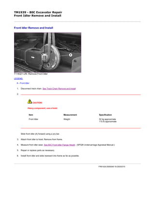
1. TM1939 - 80C Excavator Repair
Front Idler Remove and Install
T118321-UN: Remove Front Idler
LEGEND:
A - Front Idler
1. Disconnect track chain. See Track Chain Remove and Install
2.
CAUTION:
Heavy component; use a hoist.
Slide front idler (A) forward using a pry bar.
3. Attach front idler to hoist. Remove from frame.
4. Measure front idler wear. See 80C Front Idler Flange Height . (SP326 Undercarriage Appraisal Manual.)
5. Repair or replace parts as necessary.
6. Install front idler and slide rearward into frame as far as possible.
Item Measurement Specification
Front Idler Weight 52 kg approximate
115 lb approximate
FR91424,00000A9-19-20030310
1/1
2020/1/16file:///C:/ProgramData/Service%20ADVISOR/Temp/TM1939_09001faa802d4...
2. TM1939 - 80C Excavator Repair
Front Idler Disassemble
T117211-UN: Front Idler—Cross Section
LEGEND:
A - Bracket (Bearing) (2 used)
B - Pin (2 used)
C - Metal Face Seal (2 used)
D - Idler
E - Bushing (2 used)
F - Cap Screw (4 used)
G - Yoke
H - Plug (2 used)
I - O-Ring (2 used)
J - Axle
1. Remove cap screws (F). Remove yoke (G).
2. Remove drain plug (H). Drain oil.
3. IMPORTANT:
Metal face seals can be reused if they are not worn or damaged. A used seal must be kept together as a set because of wear patterns on seal ring face.
Remove pins (B), brackets (A), O-rings (I), and metal face seals (C).
4. See Metal Face Seals Inspection . (Group 0130.) Keep seal rings together as a matched set with seal ring faces together to protect surfaces.
5. Remove axle (J).
6. Inspect the bushing for scoring or excessive wear.
7. NOTE:
Remove bushings only if replacement is necessary.
Remove bushing using a 2-jaw puller and adapters from 17-1/2 and 30-ton puller set.
8. Repair or replace parts as necessary.
FR91424,00000AA-19-20030310
1/1
2020/1/16file:///C:/ProgramData/Service%20ADVISOR/Temp/TM1939_09001faa802d4...
3. TM1939 - 80C Excavator Repair
Front Idler Assemble
T117212-UN: Front Idler—Exploded View
LEGEND:
A - Bracket (Bearing) (2 used)
B - Plug (2 used)
C - Pin (2 used)
D - Metal Face Seal (2 used)
E - O-Ring (2 used)
F - Axle
G - Bushing (2 used)
H - Idler
I - Yoke
J - Cap Screw (4 used)
1. Apply a thin film of oil to bushings (G). Install bushings so flange is tight against shoulder of idler.
2. Install O-rings (E) on axle.
3. Apply a thin layer of NEVER-SEEZ® anti-seize lubricant or an equivalent to end of axle from O-ring to end of axle, and to bore in bracket (A).
4. Install axle into bracket.
5. Apply NEVER-SEEZ® anti-seize lubricant or an equivalent to pin (C). Install pin.
6. IMPORTANT:
O-rings and seat surfaces for O-rings must be clean, dry, and oil free, so O-rings do not slip when idler is turning.
Thoroughly clean the O-rings and seat surfaces in idler, bracket, and seal rings using volatile, non-petroleum base solvent and lint-free tissues.
7. Install O-ring on seal rings.
8. Install seals in bracket and idler. Apply equal pressure with fingers at four equally spaced points on seal face. Seal must “pop” down into place so O-ring is tight against seal bore.
9. NOTE:
A volatile non-petroleum base solvent or talcum powder may be used as a lubricant.
Wipe finger prints and foreign material off seal ring face using clean oil and lint-free tissues. Apply a thin film of oil to each seal ring face.
10. Install axle into idler.
11. Repeat procedure for other side of idler.
12. Fill front idler with oil.
Item Measurement Specification
Front Idler Capacity 140 mL
4.7 oz
1/2
2020/1/16file:///C:/ProgramData/Service%20ADVISOR/Temp/TM1939_09001faa802d4...
4. See Track Roller, Front Idler, and Carrier Roller Oil . (Group 0130.)
13. Clean threads of drain plug (B). Apply cure primer.
14. Apply pipe sealant and install plug.
15. Install yoke (I). Tighten cap screws (J).
Item Measurement Specification
Idler Bearing Drain Plug Torque 20 N˙m
177 lb-in.
Item Measurement Specification
Yoke-to-Bracket Cap Screw Torque 175 N˙m
130 lb-ft
NEVER-SEEZ is a trademark of Emhart Chemical Group.
LOCTITE is a trademark of Loctite Corp. FR91424,00000AB-19-20030310
2/2
2020/1/16file:///C:/ProgramData/Service%20ADVISOR/Temp/TM1939_09001faa802d4...
5. TM1939 - 80C Excavator Repair
Front Idler Oil Leakage Test
T109791B-UN: Test Front Idler for Oil Leakage
LEGEND:
A - Plug, Adapter and Connector
B - Connector 1/8 M NPT x 7/16-20 M 37°
C - Hose
D - Pressure Gauge
E - Snubber (Needle) Valve
F - Air Pressure Regulator
G - Drain Plug
1. Turn shaft several turns to seat metal face seals.
2. Remove plug (G).
3. Install parts (A—F) as shown. Plug, barbed adapter, and connector are from a leak detector kit such as the D05361ST
Rubber Stopper/Leak Detector Kit.
4. Holding plug so it is not pushed out, slowly pressurize oil cavity using air.
Item Measurement Specification
1/2
2020/1/16file:///C:/ProgramData/Service%20ADVISOR/Temp/TM1939_09001faa802d4...
6. 5. Close valve and wait for a minimum of 30 seconds to check for oil leakage. Check gauge to see if air pressure has
decreased.
6. If there is external leakage, disassemble idler and replace parts as necessary.
7. Check oil level in idler. If oil level is down and there is no external leakage, check for a leak from oil cavity to interior of
idler wheel.
8. Clean threads of plug. Apply cure primer.
9. Apply pipe sealant to threads of plug. Install and tighten plug.
Front Idler Oil Leakage Test Pressure 110 kPa
1.1 bar
16 psi
LOCTITE is a trademark of Loctite Corp. FR91424,00000AC-19-20030310
2/2
2020/1/16file:///C:/ProgramData/Service%20ADVISOR/Temp/TM1939_09001faa802d4...
7. TM1939 - 80C Excavator Repair
Track Adjuster Cylinder and Recoil Spring Remove and Install
T6557CX-UN: Recoil Spring
T6557CY-UN: Track Adjuster Cylinder
LEGEND:
A - Track Adjuster Cylinder and Recoil Spring
1. Remove track chain. See Track Chain Remove and Install . (Group 0130.)
2. Remove front idler. See Front Idler Remove and Install . (Group 0130.)
3.
CAUTION:
Spring or rod may break if dropped while handling, transporting or disassembling. Nicks or weld craters in
spring and rod assembly can cause stress concentration resulting in a weak spot that may result in
immediate or eventual failure creating a risk of personal injury. Put a heavy protective covering around
spring assembly when handling, transporting, or disassembling.
A compression tool must be used for disassembly and assembly because of the extreme preload on spring.
Slide track adjuster cylinder and recoil spring (A) forward using a pry bar.
1/2
2020/1/16file:///C:/ProgramData/Service%20ADVISOR/Temp/TM1939_09001faa802d4...
8. 4.
CAUTION:
Heavy component; use a hoist.
Remove track adjuster using a lifting strap and a hoist.
5. Repair or replace parts as necessary.
6. Install track adjuster, valve end first.
7. Install front idler. See Front Idler Remove and Install . (Group 0130.)
8. Connect track chain. See Track Chain Remove and Install . (Group 0130.)
Item Measurement Specification
Track Adjuster Cylinder and Recoil
Spring
Weight 31 kg approximate
68 lb approximate
FR91424,00000AE-19-20030310
2/2
2020/1/16file:///C:/ProgramData/Service%20ADVISOR/Temp/TM1939_09001faa802d4...
9. TM1939 - 80C Excavator Repair
Track Adjuster and Recoil Spring Disassemble and Assemble
T6557DY-UN: Assembly Tool
LEGEND:
A - ST4920 Track Recoil Spring Disassembly and Assembly Tool
B - Nut (4 used)
C - Top Plate
1.
CAUTION:
Spring or rod may break if dropped while handling, transporting or disassembling. Nicks or weld craters in
spring and rod assembly can cause stress concentration resulting in a weak spot. Weak spots can result in
immediate or eventual failure creating a risk of personal injury. Put a heavy protective covering around
spring assembly when handling, transporting, or disassembling.
A compression tool must be used for disassembly and assembly because of the extreme preload on spring.
1/5
2020/1/16file:///C:/ProgramData/Service%20ADVISOR/Temp/TM1939_09001faa802d4...
10. Place an 18-t (20-ton) jack on bottom of ST4920 Track Recoil Spring Disassembly and Assembly Tool (A). See ST4920 Recoil
Spring Disassembly and Assembly Tool for instructions to make tool. (Group 9900.)
2. Remove nuts (B). Remove top plate (C).
3.
CAUTION:
Heavy component; use a hoist.
T7720AF-UN: Track Adjuster and Assembly Tool
LEGEND:
A - Lifting Strap
B - Track Adjuster
C - DFT1112A Spacer
Connect track adjuster (B) to a hoist using a lifting strap (A).
Item Measurement Specification
Track Adjuster Cylinder and Recoil
Spring
Weight 31 kg approximate
68 lb approximate
2/5
2020/1/16file:///C:/ProgramData/Service%20ADVISOR/Temp/TM1939_09001faa802d4...
11. 4. Put track adjuster in assembly tool with cylinder end on DFT1112A Spacer (C). See DFT1112A Spacer for instructions to make tool.
(Group 9900.)
5.
T7720AG-UN: Open Assembly Adjuster
3/5
2020/1/16file:///C:/ProgramData/Service%20ADVISOR/Temp/TM1939_09001faa802d4...
12. T7720AH-UN: Closed Assembly Adjuster
LEGEND:
A - Top Plate
B - Nut (8 used)
C - Valve
D - Nut
E - Special Plug
F - DFT1087 Track Recoil Spring Disassembly and Assembly Guard Tool
Install DFT1087 Track Recoil Spring Disassembly and Assembly Guard Tool (F). See DFT1087 Track Recoil Spring Disassembly
and Assembly Guard Tool for instructions to make tool. (Group 9900.)
6. Install the top plate (A) with smallest opening to allow access to nut (D).
7. Extend jack ram so there is enough travel to release spring.
8. Tighten nuts (B) so plate is tight against retainer plate.
9. Remove valve (C). Remove special plug (E).
10. Raise upper half of guard tool. Tighten T-handles.
11. Operate jack to compress spring just enough so nut (D) can be removed.
Item Measurement Specification
Track Adjuster Cylinder Recoil
Spring
Free Length 327 mm approximate
12.9 in. approximate
4/5
2020/1/16file:///C:/ProgramData/Service%20ADVISOR/Temp/TM1939_09001faa802d4...
13. 12. Lower jack ram to release spring force.
13. Disassemble track adjuster cylinder. See Disassemble and Assemble Track Adjuster Cylinder. (Group 0130.)
14. Repair or replace parts as necessary.
15. Put track adjuster cylinder in assembly tool with cylinder end on spacer.
16. Install spacer on rod.
17. Install spring using a hoist and lifting strap.
18. Install retainer plate.
19. Install guard tool.
20. Install top plate. Install nuts.
21. Raise upper half of guard tool. Tighten T-handles.
22. Operate jack to compress spring.
23. Install nut (D) so hole is aligned with hole in rod. Install special plug (E).
24. Tighten valve (C).
25. Remove track adjuster using a lifting strap and hoist.
Item Measurement Specification
Track Adjuster Cylinder Recoil
Spring
Compressed Length 267 mm
10.5 in.
Item Measurement Specification
Track Adjuster Cylinder and Recoil
Spring Valve
Torque 147 N˙m
110 lb-ft
FR91424,00000AF-19-20030310
5/5
2020/1/16file:///C:/ProgramData/Service%20ADVISOR/Temp/TM1939_09001faa802d4...
14. Thank you very much for
your reading. Please Click
Here. Then Get COMPLETE
MANUAL. NO WAITING
NOTE:
If there is no response to
click on the link above,
please download the PDF
document first and then
click on it.
15. TM1939 - 80C Excavator Repair
Track Adjuster Cylinder Disassemble and Assemble
T117213-UN: Breakdown of Track Adjuster Cylinder
LEGEND:
A - Cap Screw (4 used)
B - Holder
C - Dust Seal
D - Flange
E - Piston Rod
F - Wear Ring
G - U-Ring (Packing)
H - Snap Ring
I - Adjuster Cylinder
J - Valve
K - Nut
L - Washer
M - Spring
N - Plug
CAUTION:
Spring or rod may break if dropped while handling, transporting or disassembling. Nicks or weld craters in spring and rod assembly can cause stress concentration resulting
in a weak spot. Weak spots can result in immediate or eventual failure of spring or rod creating a risk of personal injury. Put a heavy protective covering around spring
assembly when handling, transporting, or disassembling.
A compression tool must be used for disassembly and assembly because of the extreme preload on spring.
1. If necessary, remove recoil spring. See Track Adjuster Cylinder and Recoil Spring Remove and Install . (Group 0130.)
1/2
2020/1/16file:///C:/ProgramData/Service%20ADVISOR/Temp/TM1939_09001faa802d4...
16. 2. NOTE:
T120817-UN: Track Adjuster Cross Sectional
LEGEND:
A - Cap Screw (4 used)
B - Holder
C - Dust Seal
D - Flange
E - Piston Rod
F - Wear Ring
G - U-Ring (Packing)
H - Snap Ring
I - Adjuster Cylinder
J - Valve
K - Nut
L - Washer
M - Spring
N - Plug
O - Groove
P - Chamber
It is not necessary to remove the recoil spring to replace wear ring (F), dust seal (C), and packing (G).
If necessary, remove rod (E) from cylinder (I) using a press.
3. Repair or replace parts as necessary.
4. Apply multi-purpose grease to dust seal (C), packing (G), and wear ring (F). Fill grooves (O) inside holder (B) with grease.
5. Install packing (G) with lip towards inside of cylinder.
6. Fill chamber (P) in cylinder with grease. Insert piston rod (E) into cylinder (I) to bleed air remaining in the cylinder.
7. Tighten cap screws (A).
Item Measurement Specification
Flange-to-Adjuster Cylinder Cap
Screw
Torque 30 N˙m
22 lb-ft
FR91424,00000B1-19-20030310
2/2
2020/1/16file:///C:/ProgramData/Service%20ADVISOR/Temp/TM1939_09001faa802d4...
17. TM1939 - 80C Excavator Repair
Propel Gearbox Remove and Install
1. Disconnect track chain. See Track Chain Remove and Install . (Group 0130.)
2.
CAUTION:
The hydraulic oil tank is pressurized. High pressure release of oil can cause serious burns or penetrating
injury.
Perform Hydraulic Oil Tank Pressure Release Procedure . (Group 3360.)
3. Pull vacuum in hydraulic oil tank using vacuum pump or drain hydraulic oil tank. Approximate capacity is 58.7 L (15.5 gal).
4. Remove cover from propel motor.
5. Disconnect lines.
6.
T189127B-UN: Propel Gearbox Cap Screws
LEGEND:
1 - Cap Screw (10 used)
Attach propel gearbox to hoist using lifting strap.
CAUTION:
Heavy component; use a hoist.
1/2
2020/1/16file:///C:/ProgramData/Service%20ADVISOR/Temp/TM1939_09001faa802d4...
18. 7. NOTE:
Make alignment marks between propel gearbox and undercarriage to aid in installation.
Remove cap screws (1). Remove propel gearbox, propel motor, and sprocket.
8. Repair or replace parts as necessary.
9. NOTE:
Align marks made during removal.
Install gearbox. Tighten cap screws (1).
10. Connect lines. See Propel And Blade Hydraulic System Line Connection . (Group 9025-15.)
11. Fill hydraulic oil tank.See Drain and Refill Capacities. (Operator's Manual.)
12. Check propel gearbox oil level.See Check Propel Gearbox Oil Level. (Operator's Manual.)
13. Perform Propel Motor Start-Up Procedure . (Group 0260.)
14. Install cover.
15. Connect track chain. See Track Chain Remove and Install . (Group 0130.)
16. Perform Check and Adjust Track Sag . (Group 0130.)
Item Measurement Specification
Propel Gearbox with Sprocket Weight 130 kg approximate
285 lb approximate
Item Measurement Specification
Propel Gearbox-to-Frame Cap
Screw
Torque 300 N˙m
220 lb-ft
TX19495,000002F-19-20030326
2/2
2020/1/16file:///C:/ProgramData/Service%20ADVISOR/Temp/TM1939_09001faa802d4...