Download as PDF, PPTX
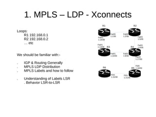


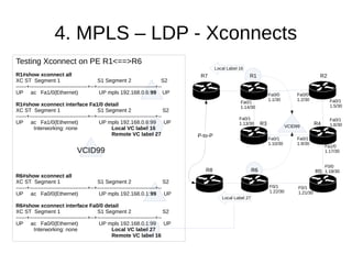


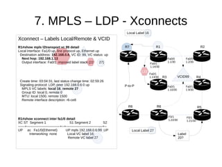


The document discusses MPLS LDP configurations for establishing xconnect circuits to connect customer edge routers CE-R7 and CE-R8 to provider edge routers R1 and R6 respectively. Interface configurations on R1 and R6 set up xconnects with encapsulation MPLS and VC IDs. Show commands confirm the local and remote VC labels exchanged via LDP signaling and the end-to-end MPLS label stacks imposed.


