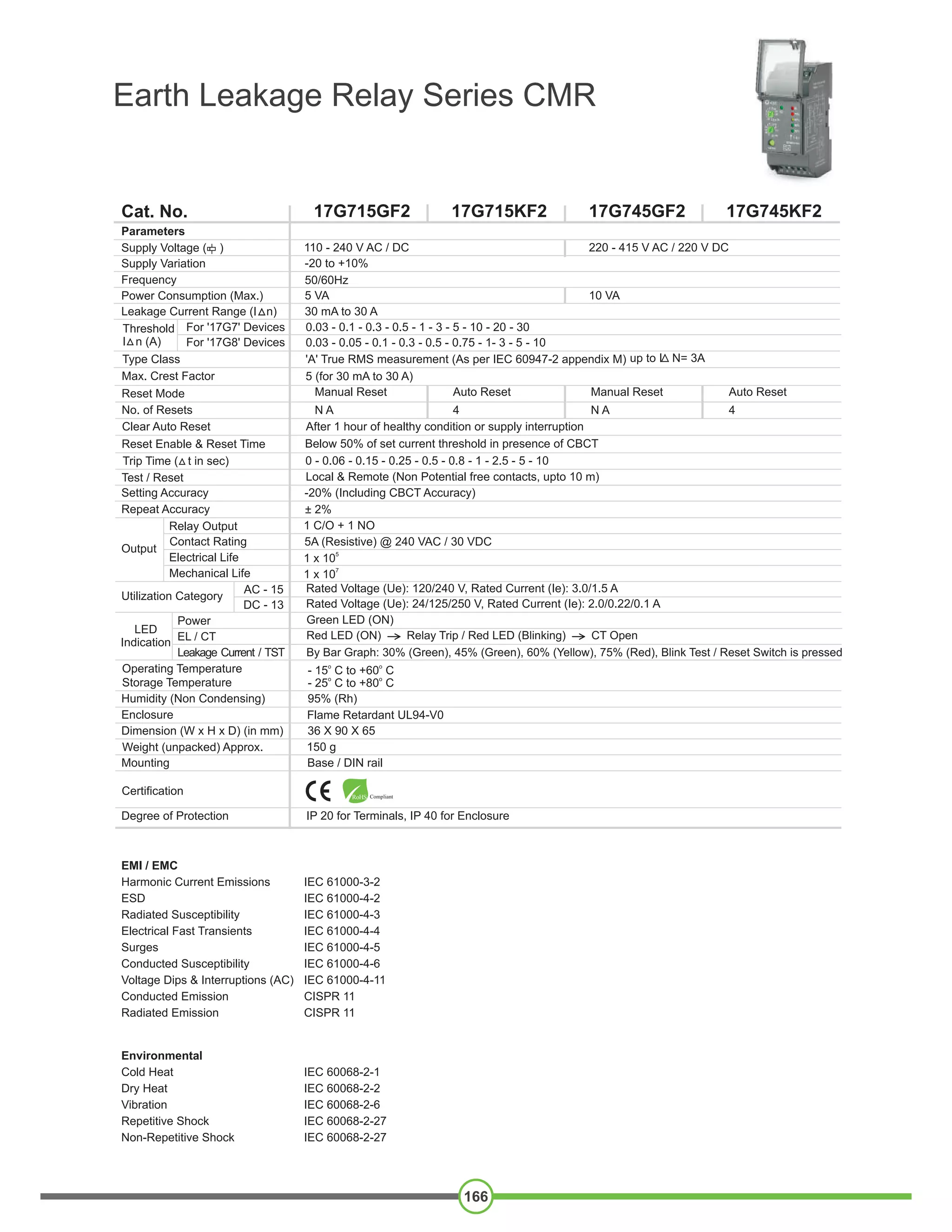
165
Earth Leakage Relay Series CMR
• Instantaneous Trip for 5 times of set value of
Leakage current
• Test feature to check complete product functionality
• LED Indication for Relay status, CT open,
Earth Leakage fault & Test/Reset switch feature
• Manual / Remote Reset feature
• 1 C/O + 1 NO Relay Output
• Monitors, Detects and Protects Power systems
from Earth Leakage Faults
• Wide range of selectable Earth Leakage Current:
30 mA - 30 A
• Configurable Earth Leakage Trip time: 0 - 10 s
• Wide Auxiliary Supply Range:
110 - 240 V AC / DC,
220 - 415 V AC / 220 V DC
Ordering Information
Cat. No. Description
17G715GF2 110-240V AC / DC, Current Range 30 mA - 30 A, 1 C/O + 1 NO, Manual Reset
17G715KF2 110-240V AC / DC, Current Range 30 mA - 30 A, 1 C/O + 1 NO, Auto Reset
17G745GF2 220-415V AC / 220 V DC, Current Range 30 mA - 30 A, 1 C/O + 1 NO, Manual Reset
17G745KF2 220-415V AC / 220 V DC, Current Range 30 mA - 30 A, 1 C/O + 1 NO, Auto Reset
17G755GF2 15V DC, Current Range 30 mA - 30 A, 1 C/O + 1 NO, Manual Reset
17G755KF2 15V DC, Current Range 30 mA - 30 A, 1 C/O + 1 NO, Auto Reset
17G815GF2 110-240V AC / DC, Current Range 30 mA - 10 A, 1 C/O + 1 NO, Manual Reset
17G815KF2 110-240V AC / DC, Current Range 30 mA - 10 A, 1 C/O + 1 NO, Auto Reset
17G845GF2 220-415V AC / 220 V DC, Current Range 30 mA - 10 A, 1 C/O + 1 NO, Manual Reset
17G845KF2 220-415V AC / 220 V DC, Current Range 30 mA - 10 A, 1 C/O + 1 NO, Auto Reset
Note: For CBCT ordering information please refer to page no 161.
Earth Leakage Relay Series CMR
166
Cat. No.
Parameters
Power Consumption (Max.)
220 - 415 V AC / 220 V DC
50/60Hz
17G715GF2 17G745GF2
110 - 240 V AC / DC
-20 to +10%
10 VA5 VA
30 mA to 30 A
17G715KF2 17G745KF2
Supply Voltage ( )
Supply Variation
Frequency
Leakage Current Range (I n)
0.03 - 0.1 - 0.3 - 0.5 - 1 - 3 - 5 - 10 - 20 - 30Threshold
I n (A)
Reset Mode
No. of Resets 4N A N A 4
Clear Auto Reset After 1 hour of healthy condition or supply interruption
Reset Enable & Reset Time Below 50% of set current threshold in presence of CBCT
Manual Reset Manual ResetAuto Reset Auto Reset
Type Class 'A' True RMS measurement (As per IEC 60947-2 appendix M)
Max. Crest Factor 5 (for 30 mA to 30 A)
Test / Reset Local & Remote (Non Potential free contacts, upto 10 m)
0 - 0.06 - 0.15 - 0.25 - 0.5 - 0.8 - 1 - 2.5 - 5 - 10Trip Time ( t in sec)
-20% (Including CBCT Accuracy)
± 2%
Setting Accuracy
Repeat Accuracy
Utilization Category
AC - 15
DC - 13
Rated Voltage (Ue): 120/240 V, Rated Current (Ie): 3.0/1.5 A
Rated Voltage (Ue): 24/125/250 V, Rated Current (Ie): 2.0/0.22/0.1 A
5
1 x 10
7
1 x 10
5A (Resistive) @ 240 VAC / 30 VDC
1 C/O + 1 NORelay Output
Output
Contact Rating
Electrical Life
Mechanical Life
Humidity (Non Condensing) 95% (Rh)
Operating Temperature
Storage Temperature
o o
- 15 C to +60 C
o o
- 25 C to +80 C
Degree of Protection 20 f r al 40 f r osuIP o Termin s, IP o Encl re
Certification RoHS Compliant
Enclosure F a e R a t 4l m et rdan UL9 -V0
Dimension (W x H x D) (in mm) 36 X 90 X 65
51 0 gWeight (unpacked) Approx.
Mounting Base / DIN rail
Green LED (ON)Power
Leakage Current / TST
EL / CT
By Bar Graph: 30% (Green), 45% (Green), 60% (Yellow), 75% (Red), Blink Test / Reset Switch is pressed
LED
Indication
Red LED (ON) Relay Trip / Red LED (Blinking) CT Open
EMI / EMC
Harmonic Current Emissions IEC 61000-3-2
ESD IEC 61000-4-2
Radiated Susceptibility IEC 61000-4-3
Electrical Fast Transients IEC 61000-4-4
Surges IEC 61000-4-5
Conducted Susceptibility IEC 61000-4-6
Voltage Dips & Interruptions (AC) IEC 61000-4-11
Conducted Emission CISPR 11
Radiated Emission CISPR 11
Environmental
Cold Heat IEC 60068-2-1
Dry Heat IEC 60068-2-2
Vibration IEC 60068-2-6
Repetitive Shock IEC 60068-2-27
Non-Repetitive Shock IEC 60068-2-27
0.03 - 0.05 - 0.1 - 0.3 - 0.5 - 0.75 - 1- 3 - 5 - 10
For '17G7' Devices
For '17G8' Devices
up to I N= 3A
FAIL SAFE MODE WITH CONTACTORFAIL SAFE MODE WITH UV TRIP COIL
CBCT
REMOTE
RESETSWITCH
ALARM
15 16 18 Y2
L1 Y1B2B1L2
25 28
250mAFuse
MCCB
with UV
Trip Coil
L2
L1
E
L3
N
NON-FAIL SAFE MODE WITH CONTACTOR NON-FAIL SAFE MODE WITH SHUNT TRIP COILNON-FAIL SAFE MODE WITH UV TRIP COIL
SINGLE PHASE APPLICATION
CBCT
ALARM
15 16 18 Y2
L1
L2
L1
E
L3
N
Y1B2B1L2
25 28
250mAFuse
CONT-
ACTOR
REMOTE
RESETSWITCH
L2
L1
E
L3
N
LAMP
15 16 18 Y2
L1 Y1B2B1L2
25 28
250mAFuse
CBCT
MCCB
with
Shunt
Trip Coil
REMOTE
RESETSWITCH
L2
L1
E
L3
N
LAMP
15 16 18 Y2
L1 Y1B2B1L2
25 28
250mAFuse
CONT-
ACTOR
CBCT
REMOTE
RESETSWITCH
15 16 18 25 28
250mAFuse
L/+
E
L/+
N/-
E
N/- B1B2 Y1
Y2
REMOTE
RESETSWITCH
CBCT
CONNECTION DIAGRAM
Earth Leakage Relay Series CMR
167
L2
L1
E
L3
N
LAMP
15 16 18 Y2
L1 Y1B2B1L2
25 28
250mAFuse
MCCB
with UV
Trip Coil
REMOTE
RESETSWITCH
CBCT
Earth Leakage Relay Series CMR
168
Dimensions in mm
A B DC E
20
20
20
20
20
20.5
71
97
109
132
153
250
91
117
133
155
176
282
27
27
36
27
27
28
48
55
59
73
73
128
CBCT
17H7NNHN3
17H7NNIN3
17H7NNQN3
17H7NNJN3
17H7NNLN3
17H7NNKN3
SIZE
38
57
70
92
120
210
110
185
240
250
255
280
WEIGHT
(in gms)
MOUNTING DIMENSIONS
TERMINAL TORQUE & CAPACITY
B
D
C
E
A
Ø 3.5
AWG
0.54 N.m (6 Lb.in)
2
1 x 2.5 mm Solid Wire/Stranded
1 x 24 to 12

Motor protection relay

  • 1.
    165 Earth Leakage RelaySeries CMR • Instantaneous Trip for 5 times of set value of Leakage current • Test feature to check complete product functionality • LED Indication for Relay status, CT open, Earth Leakage fault & Test/Reset switch feature • Manual / Remote Reset feature • 1 C/O + 1 NO Relay Output • Monitors, Detects and Protects Power systems from Earth Leakage Faults • Wide range of selectable Earth Leakage Current: 30 mA - 30 A • Configurable Earth Leakage Trip time: 0 - 10 s • Wide Auxiliary Supply Range: 110 - 240 V AC / DC, 220 - 415 V AC / 220 V DC Ordering Information Cat. No. Description 17G715GF2 110-240V AC / DC, Current Range 30 mA - 30 A, 1 C/O + 1 NO, Manual Reset 17G715KF2 110-240V AC / DC, Current Range 30 mA - 30 A, 1 C/O + 1 NO, Auto Reset 17G745GF2 220-415V AC / 220 V DC, Current Range 30 mA - 30 A, 1 C/O + 1 NO, Manual Reset 17G745KF2 220-415V AC / 220 V DC, Current Range 30 mA - 30 A, 1 C/O + 1 NO, Auto Reset 17G755GF2 15V DC, Current Range 30 mA - 30 A, 1 C/O + 1 NO, Manual Reset 17G755KF2 15V DC, Current Range 30 mA - 30 A, 1 C/O + 1 NO, Auto Reset 17G815GF2 110-240V AC / DC, Current Range 30 mA - 10 A, 1 C/O + 1 NO, Manual Reset 17G815KF2 110-240V AC / DC, Current Range 30 mA - 10 A, 1 C/O + 1 NO, Auto Reset 17G845GF2 220-415V AC / 220 V DC, Current Range 30 mA - 10 A, 1 C/O + 1 NO, Manual Reset 17G845KF2 220-415V AC / 220 V DC, Current Range 30 mA - 10 A, 1 C/O + 1 NO, Auto Reset Note: For CBCT ordering information please refer to page no 161.
  • 2.
    Earth Leakage RelaySeries CMR 166 Cat. No. Parameters Power Consumption (Max.) 220 - 415 V AC / 220 V DC 50/60Hz 17G715GF2 17G745GF2 110 - 240 V AC / DC -20 to +10% 10 VA5 VA 30 mA to 30 A 17G715KF2 17G745KF2 Supply Voltage ( ) Supply Variation Frequency Leakage Current Range (I n) 0.03 - 0.1 - 0.3 - 0.5 - 1 - 3 - 5 - 10 - 20 - 30Threshold I n (A) Reset Mode No. of Resets 4N A N A 4 Clear Auto Reset After 1 hour of healthy condition or supply interruption Reset Enable & Reset Time Below 50% of set current threshold in presence of CBCT Manual Reset Manual ResetAuto Reset Auto Reset Type Class 'A' True RMS measurement (As per IEC 60947-2 appendix M) Max. Crest Factor 5 (for 30 mA to 30 A) Test / Reset Local & Remote (Non Potential free contacts, upto 10 m) 0 - 0.06 - 0.15 - 0.25 - 0.5 - 0.8 - 1 - 2.5 - 5 - 10Trip Time ( t in sec) -20% (Including CBCT Accuracy) ± 2% Setting Accuracy Repeat Accuracy Utilization Category AC - 15 DC - 13 Rated Voltage (Ue): 120/240 V, Rated Current (Ie): 3.0/1.5 A Rated Voltage (Ue): 24/125/250 V, Rated Current (Ie): 2.0/0.22/0.1 A 5 1 x 10 7 1 x 10 5A (Resistive) @ 240 VAC / 30 VDC 1 C/O + 1 NORelay Output Output Contact Rating Electrical Life Mechanical Life Humidity (Non Condensing) 95% (Rh) Operating Temperature Storage Temperature o o - 15 C to +60 C o o - 25 C to +80 C Degree of Protection 20 f r al 40 f r osuIP o Termin s, IP o Encl re Certification RoHS Compliant Enclosure F a e R a t 4l m et rdan UL9 -V0 Dimension (W x H x D) (in mm) 36 X 90 X 65 51 0 gWeight (unpacked) Approx. Mounting Base / DIN rail Green LED (ON)Power Leakage Current / TST EL / CT By Bar Graph: 30% (Green), 45% (Green), 60% (Yellow), 75% (Red), Blink Test / Reset Switch is pressed LED Indication Red LED (ON) Relay Trip / Red LED (Blinking) CT Open EMI / EMC Harmonic Current Emissions IEC 61000-3-2 ESD IEC 61000-4-2 Radiated Susceptibility IEC 61000-4-3 Electrical Fast Transients IEC 61000-4-4 Surges IEC 61000-4-5 Conducted Susceptibility IEC 61000-4-6 Voltage Dips & Interruptions (AC) IEC 61000-4-11 Conducted Emission CISPR 11 Radiated Emission CISPR 11 Environmental Cold Heat IEC 60068-2-1 Dry Heat IEC 60068-2-2 Vibration IEC 60068-2-6 Repetitive Shock IEC 60068-2-27 Non-Repetitive Shock IEC 60068-2-27 0.03 - 0.05 - 0.1 - 0.3 - 0.5 - 0.75 - 1- 3 - 5 - 10 For '17G7' Devices For '17G8' Devices up to I N= 3A
  • 3.
    FAIL SAFE MODEWITH CONTACTORFAIL SAFE MODE WITH UV TRIP COIL CBCT REMOTE RESETSWITCH ALARM 15 16 18 Y2 L1 Y1B2B1L2 25 28 250mAFuse MCCB with UV Trip Coil L2 L1 E L3 N NON-FAIL SAFE MODE WITH CONTACTOR NON-FAIL SAFE MODE WITH SHUNT TRIP COILNON-FAIL SAFE MODE WITH UV TRIP COIL SINGLE PHASE APPLICATION CBCT ALARM 15 16 18 Y2 L1 L2 L1 E L3 N Y1B2B1L2 25 28 250mAFuse CONT- ACTOR REMOTE RESETSWITCH L2 L1 E L3 N LAMP 15 16 18 Y2 L1 Y1B2B1L2 25 28 250mAFuse CBCT MCCB with Shunt Trip Coil REMOTE RESETSWITCH L2 L1 E L3 N LAMP 15 16 18 Y2 L1 Y1B2B1L2 25 28 250mAFuse CONT- ACTOR CBCT REMOTE RESETSWITCH 15 16 18 25 28 250mAFuse L/+ E L/+ N/- E N/- B1B2 Y1 Y2 REMOTE RESETSWITCH CBCT CONNECTION DIAGRAM Earth Leakage Relay Series CMR 167 L2 L1 E L3 N LAMP 15 16 18 Y2 L1 Y1B2B1L2 25 28 250mAFuse MCCB with UV Trip Coil REMOTE RESETSWITCH CBCT
  • 4.
    Earth Leakage RelaySeries CMR 168 Dimensions in mm A B DC E 20 20 20 20 20 20.5 71 97 109 132 153 250 91 117 133 155 176 282 27 27 36 27 27 28 48 55 59 73 73 128 CBCT 17H7NNHN3 17H7NNIN3 17H7NNQN3 17H7NNJN3 17H7NNLN3 17H7NNKN3 SIZE 38 57 70 92 120 210 110 185 240 250 255 280 WEIGHT (in gms) MOUNTING DIMENSIONS TERMINAL TORQUE & CAPACITY B D C E A Ø 3.5 AWG 0.54 N.m (6 Lb.in) 2 1 x 2.5 mm Solid Wire/Stranded 1 x 24 to 12