Download to read offline


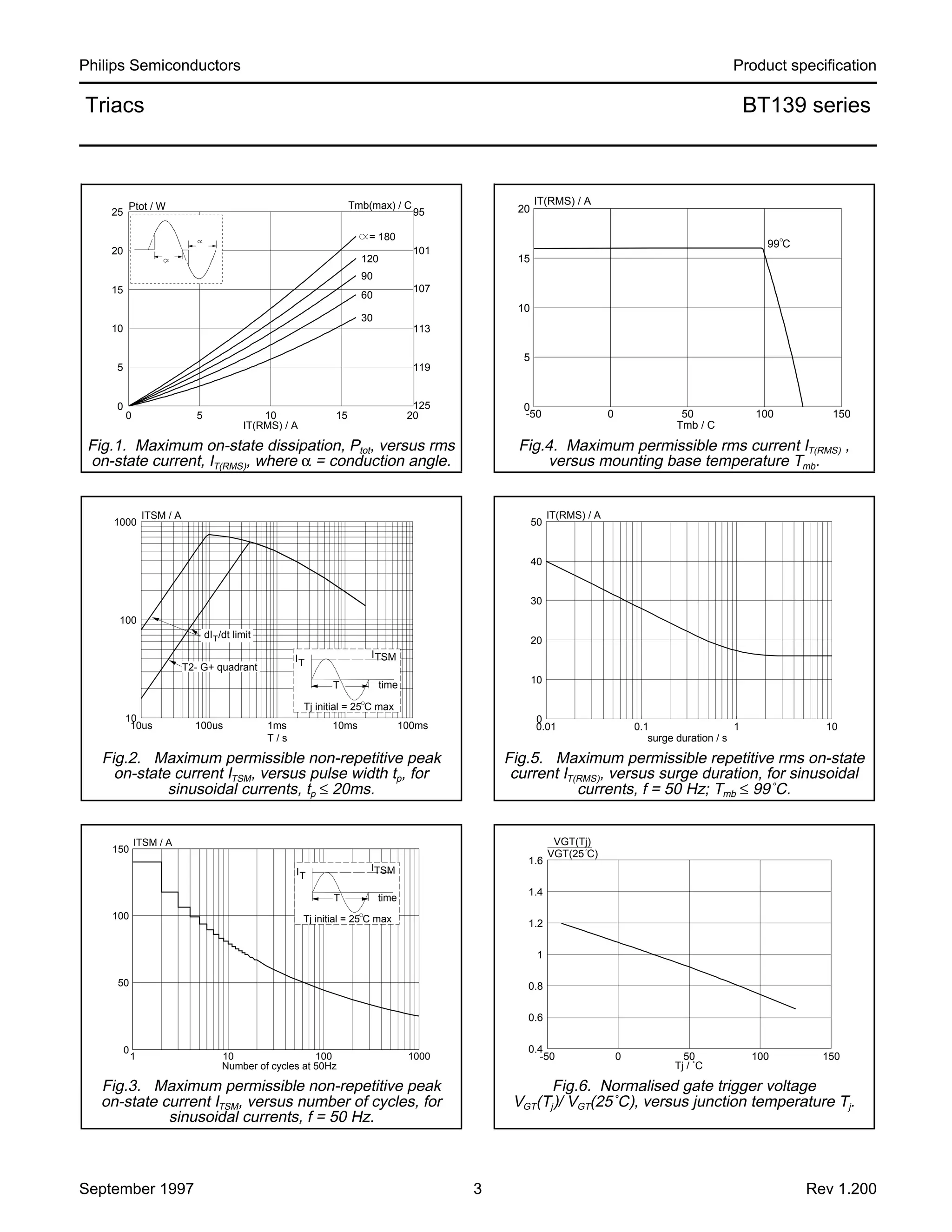
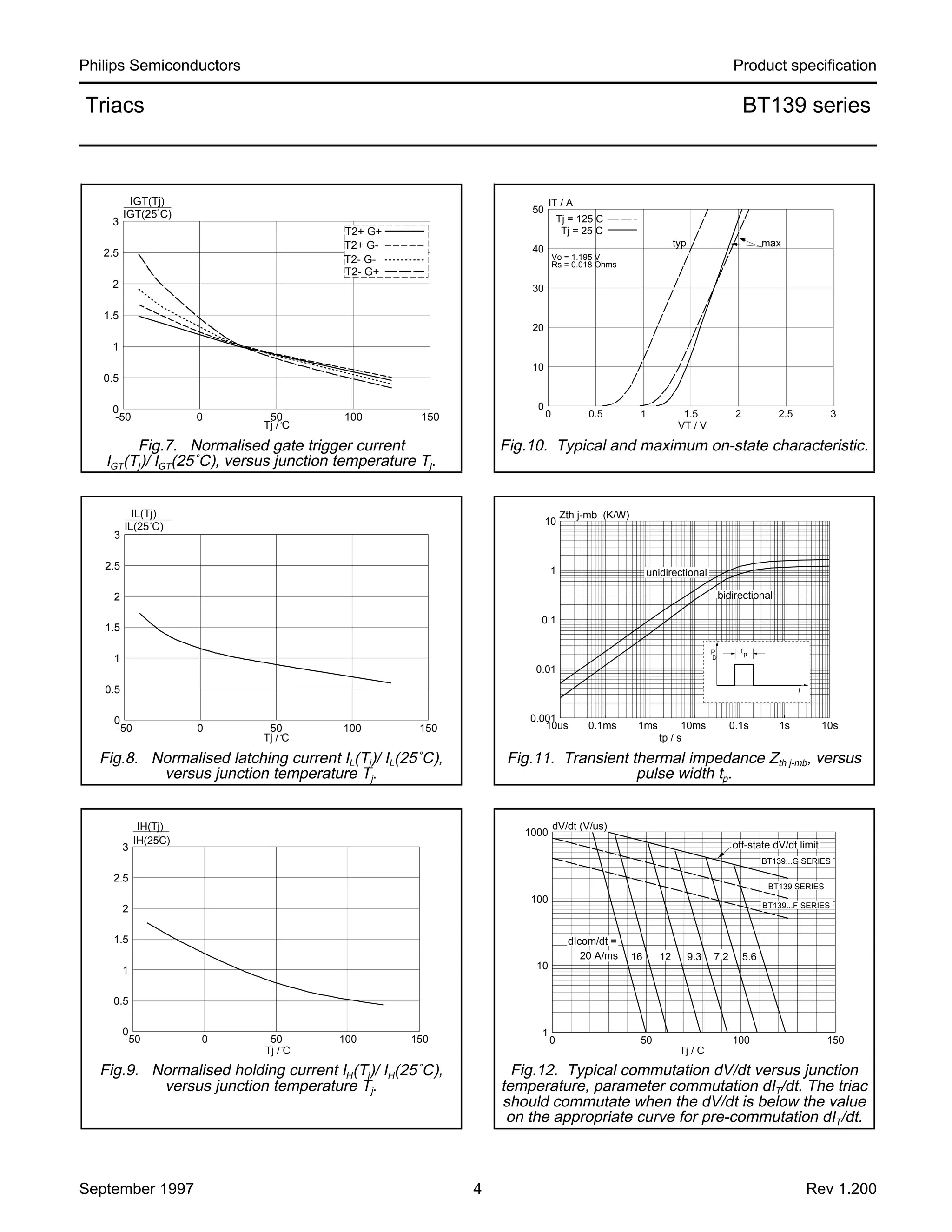


This document provides product specifications for Philips Semiconductors Triacs BT139 series. The BT139 series are glass passivated triacs in a plastic envelope intended for applications requiring high bidirectional transient blocking voltage and thermal cycling performance such as motor control, lighting, heating, and switching. Key specifications include maximum repetitive peak off-state voltages of 500-800V, RMS on-state current of 16A, and non-repetitive peak on-state current of 140A. The document provides detailed electrical parameters, thermal characteristics, and mechanical dimensions for the BT139 series triacs.