The document summarizes the design and construction of the foundations for the Rion Antirion Bridge in Greece. Key points:
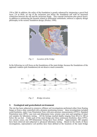
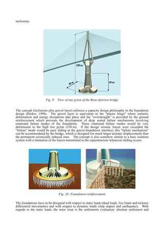
1) The foundations used an innovative design of large diameter gravity caissons resting on reinforced natural ground, with steel tubular inclusions and a gravel layer, to address weak soil conditions, seismic activity, and tectonic movements.
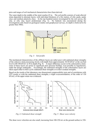
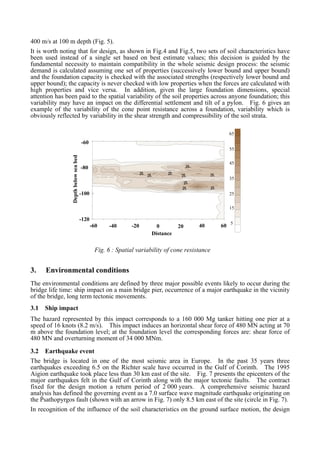
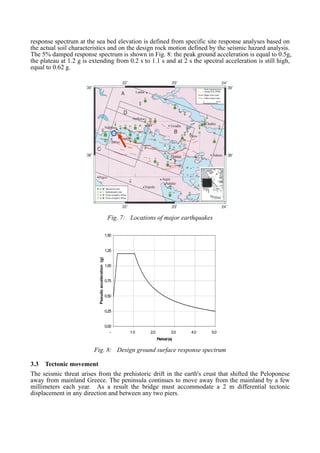
2) Subsurface investigations found deep alluvial deposits with low strength and shear wave velocities, posing challenges for the large bridge piers.
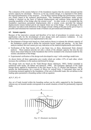
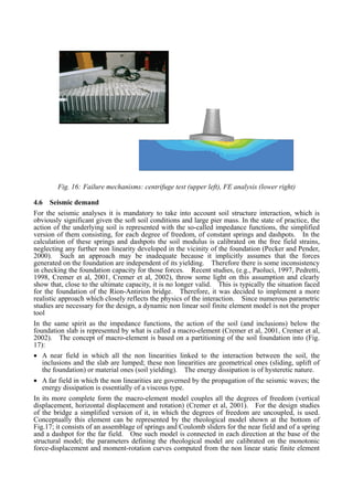
3) The foundation concept used capacity design principles, with the gravel layer absorbing inelastic deformations and inclusions providing overstrength to prevent deep failures, allowing sliding if design loads were exceeded.
Practices in Planning, Design and Construction of Head Race Tunnel of a Hydro...Mohit Shukla
This paper has been selected for oral presentation as well as inclusion in the conference proceedings of the ICCCGE 2016 : 18th International Conference on Civil,Construction and Geological Engineering held in Toronto, Canada during June,
13-14, 2016. This paper was also able to find a position in the international conference of Dams and Hydropower held at Laos in May 2016.
Tunnelling is a serious engineering project.
In addition to large investment cost, the challenges related to long and deep tunnels are considerable.
Important aspects which needs to be considered are related to the construction works, geology, environment and operation. his module highlights all these aspects.
The pattern of Slopes Pattern in Rock Media
By: Omitogun Solomon T.
Student(MSc. Geology-Engineering Geology/Hydrogeology-2018/2019 set) University of Lagos, Nigeria
solotosin6@gmail.com
Analysis and Design Aspects of Support Measures of Main Caverns of Karuma Hyd...IOSRJMCE
The Power house complex of Karuma Hydropower project comprises three main caverns i.e Power house, Transformer Hall and Tailrace surge gallery set at a depth of about 80m in mainly granitic gneiss rock medium. The cavern has been oriented in a N141° direction based on engineering considerations. The principle stress direction is also found nearly parallel to the axis of the caverns and thus the present orientation satisfies both engineering and geotechnical criteria. The support by way of rock anchors and SFRS/ Plain shotcrete has been provided based on analysis using phase 2 software. The underground caverns lie in low geostress field and therefore numerical simulation of excavation of these caverns were done to understand the rock mass behavior during excavation and thus help in design of excavation sequence and rock support. The excavation of all three caverns has since been completed and concrete works are in progress. This paper sums up the 3D simulation analysis of the rock medium and the proposed rock support system for the three caverns.
A presentation about roads and highways- it's study and also some problems after the construction of roads.the presentation also contains pictures of complicated regions for road construction.
Challenges of Tunneling-- A Peep Into The Exciting World of TunnellingIEI GSC
By Shri Manoj Verman, President, Indian National Group of ISRM
President, International Commission on Hard Rock Excavation
Vice President, Indian Society of Engineering Geology
at 31st National Convention of Civil Engineering
organised by
Gujarat State Center, The Institution of Engineers (India)
at Ahmedabad
VARIATION OF SEISMIC RESPONSE OF MID-RISE RC BUILDINGS DUE TO SOIL STRUCTURE ...IAEME Publication
The seismic design of RC buildings requires determining the expected base shear, lateral drift at each story level and internal forces of the structural elements. In the analysis, it is common for the structural engineers to consider a fixed base structure which means that the foundations and the underlying soil are assumed to be infinitely rigid. This assumption is not proper since the underlying soil in the near field often consists of soft soil layers that possess different properties and may behave nonlinearly leading to drastic variation of the seismic motion before hitting the structure foundation. In addition, the mutual interaction between the structure, its foundation and the underlying soil during the vibrations can substantially alter the structure response. This response variation depends on the structure characteristics, the soil properties and the nature of the seismic excitation. Consequently, an accurate assessment of inertial forces and displacements in structures requires a rational treatment of soil structure interaction (SSI) effects.
Краткосрочная программа дополнительного образования «Основы предпринимательства»TCenter500
Краткосрочная программа дополнительного образования «Основы предпринимательства».Рубин Ю.Б., Заслуженный работник высшей школы РФ, член-корр. Российской академии образования, д.э.н., проф., ректор МФПУ «Синергия», президент Национальной ассоциации обучения предпринимательству
DYNAMIC ANALYSIS OF CONCRETE GIRDER BRIDGES UNDER STRONG EARTHQUAKES: THE EFF...IAEME Publication
This paper presents the dynamic analysis of concrete girder bridges taking into account the effect of collision on parapet wall. In addition, adopting of seismic isolation rubber on pier structure and wing wall on parapet were analyzed. Two spans concrete girder bridges with variation of gap were examined in theoretically by 3D FEM model of ABAQUS. The abutment was simplified by parapet wall which was modeled by 3D reinforced concrete structure. In order to examine the seismic behavior of bridge, six different inputs of seismic ground accelerations were applied at footing of pier structure.
Back analysis of high tunnel convergences in clayey marlsSYSTRA
Ganntas Tunnel is part of the modernization project of the
railway between Alger and Oran, in Algeria. In order to double
and rectify the existing line between El Affroun and Khémis
Miliana, the alignment foresees the excavation of a 7km-long
twin tunnel. The excavation works started in June 2011 with
the contractor CCECC, under the supervision of SYSTRA.
Excavation is driven in conventional method by hydraulic
hammer simultaneously on 8 different faces since excavation
was started also from a junction window towards the middle
of the tunnel. The minimum longitudinal distance to be
respected between two contiguous tunnel faces has been set
to 30m. The tunnel cross-section is a 70m² oval shaped profile,
temporary support consists of shotcrete, bolts and steel ribs.
A 30 to 50cm thick cast in situ concrete final lining is provided
as well.
When the tunnel reached a fault zone in soft clayey marls,
extreme squeezing occurred, works were stopped, and reprofiling
operations were carried out along more than 100m
tunnel length. To date, works proceed at slow rate since high
convergences are still monitored and completion of works is
not expected before December 2016.
Written by SYSTRA tunnel experts : MISANO Edoardo, COUBRAY Jean-Louis,
ESPINOZA CARMONA Fabiola
Generating a custom Ruby SDK for your web service or Rails API using Smithyg2nightmarescribd
Have you ever wanted a Ruby client API to communicate with your web service? Smithy is a protocol-agnostic language for defining services and SDKs. Smithy Ruby is an implementation of Smithy that generates a Ruby SDK using a Smithy model. In this talk, we will explore Smithy and Smithy Ruby to learn how to generate custom feature-rich SDKs that can communicate with any web service, such as a Rails JSON API.
Essentials of Automations: Optimizing FME Workflows with ParametersSafe Software
Are you looking to streamline your workflows and boost your projects’ efficiency? Do you find yourself searching for ways to add flexibility and control over your FME workflows? If so, you’re in the right place.
Join us for an insightful dive into the world of FME parameters, a critical element in optimizing workflow efficiency. This webinar marks the beginning of our three-part “Essentials of Automation” series. This first webinar is designed to equip you with the knowledge and skills to utilize parameters effectively: enhancing the flexibility, maintainability, and user control of your FME projects.
Here’s what you’ll gain:
- Essentials of FME Parameters: Understand the pivotal role of parameters, including Reader/Writer, Transformer, User, and FME Flow categories. Discover how they are the key to unlocking automation and optimization within your workflows.
- Practical Applications in FME Form: Delve into key user parameter types including choice, connections, and file URLs. Allow users to control how a workflow runs, making your workflows more reusable. Learn to import values and deliver the best user experience for your workflows while enhancing accuracy.
- Optimization Strategies in FME Flow: Explore the creation and strategic deployment of parameters in FME Flow, including the use of deployment and geometry parameters, to maximize workflow efficiency.
- Pro Tips for Success: Gain insights on parameterizing connections and leveraging new features like Conditional Visibility for clarity and simplicity.
We’ll wrap up with a glimpse into future webinars, followed by a Q&A session to address your specific questions surrounding this topic.
Don’t miss this opportunity to elevate your FME expertise and drive your projects to new heights of efficiency.
LF Energy Webinar: Electrical Grid Modelling and Simulation Through PowSyBl -...DanBrown980551
Do you want to learn how to model and simulate an electrical network from scratch in under an hour?
Then welcome to this PowSyBl workshop, hosted by Rte, the French Transmission System Operator (TSO)!
During the webinar, you will discover the PowSyBl ecosystem as well as handle and study an electrical network through an interactive Python notebook.
PowSyBl is an open source project hosted by LF Energy, which offers a comprehensive set of features for electrical grid modelling and simulation. Among other advanced features, PowSyBl provides:
- A fully editable and extendable library for grid component modelling;
- Visualization tools to display your network;
- Grid simulation tools, such as power flows, security analyses (with or without remedial actions) and sensitivity analyses;
The framework is mostly written in Java, with a Python binding so that Python developers can access PowSyBl functionalities as well.
What you will learn during the webinar:
- For beginners: discover PowSyBl's functionalities through a quick general presentation and the notebook, without needing any expert coding skills;
- For advanced developers: master the skills to efficiently apply PowSyBl functionalities to your real-world scenarios.
State of ICS and IoT Cyber Threat Landscape Report 2024 previewPrayukth K V
The IoT and OT threat landscape report has been prepared by the Threat Research Team at Sectrio using data from Sectrio, cyber threat intelligence farming facilities spread across over 85 cities around the world. In addition, Sectrio also runs AI-based advanced threat and payload engagement facilities that serve as sinks to attract and engage sophisticated threat actors, and newer malware including new variants and latent threats that are at an earlier stage of development.
The latest edition of the OT/ICS and IoT security Threat Landscape Report 2024 also covers:
State of global ICS asset and network exposure
Sectoral targets and attacks as well as the cost of ransom
Global APT activity, AI usage, actor and tactic profiles, and implications
Rise in volumes of AI-powered cyberattacks
Major cyber events in 2024
Malware and malicious payload trends
Cyberattack types and targets
Vulnerability exploit attempts on CVEs
Attacks on counties – USA
Expansion of bot farms – how, where, and why
In-depth analysis of the cyber threat landscape across North America, South America, Europe, APAC, and the Middle East
Why are attacks on smart factories rising?
Cyber risk predictions
Axis of attacks – Europe
Systemic attacks in the Middle East
Download the full report from here:
https://sectrio.com/resources/ot-threat-landscape-reports/sectrio-releases-ot-ics-and-iot-security-threat-landscape-report-2024/
DevOps and Testing slides at DASA ConnectKari Kakkonen
My and Rik Marselis slides at 30.5.2024 DASA Connect conference. We discuss about what is testing, then what is agile testing and finally what is Testing in DevOps. Finally we had lovely workshop with the participants trying to find out different ways to think about quality and testing in different parts of the DevOps infinity loop.
Connector Corner: Automate dynamic content and events by pushing a buttonDianaGray10
Here is something new! In our next Connector Corner webinar, we will demonstrate how you can use a single workflow to:
Create a campaign using Mailchimp with merge tags/fields
Send an interactive Slack channel message (using buttons)
Have the message received by managers and peers along with a test email for review
But there’s more:
In a second workflow supporting the same use case, you’ll see:
Your campaign sent to target colleagues for approval
If the “Approve” button is clicked, a Jira/Zendesk ticket is created for the marketing design team
But—if the “Reject” button is pushed, colleagues will be alerted via Slack message
Join us to learn more about this new, human-in-the-loop capability, brought to you by Integration Service connectors.
And...
Speakers:
Akshay Agnihotri, Product Manager
Charlie Greenberg, Host
Smart TV Buyer Insights Survey 2024 by 91mobiles.pdf91mobiles
91mobiles recently conducted a Smart TV Buyer Insights Survey in which we asked over 3,000 respondents about the TV they own, aspects they look at on a new TV, and their TV buying preferences.
Slack (or Teams) Automation for Bonterra Impact Management (fka Social Soluti...Jeffrey Haguewood
Sidekick Solutions uses Bonterra Impact Management (fka Social Solutions Apricot) and automation solutions to integrate data for business workflows.
We believe integration and automation are essential to user experience and the promise of efficient work through technology. Automation is the critical ingredient to realizing that full vision. We develop integration products and services for Bonterra Case Management software to support the deployment of automations for a variety of use cases.
This video focuses on the notifications, alerts, and approval requests using Slack for Bonterra Impact Management. The solutions covered in this webinar can also be deployed for Microsoft Teams.
Interested in deploying notification automations for Bonterra Impact Management? Contact us at sales@sidekicksolutionsllc.com to discuss next steps.
Transcript: Selling digital books in 2024: Insights from industry leaders - T...BookNet Canada
The publishing industry has been selling digital audiobooks and ebooks for over a decade and has found its groove. What’s changed? What has stayed the same? Where do we go from here? Join a group of leading sales peers from across the industry for a conversation about the lessons learned since the popularization of digital books, best practices, digital book supply chain management, and more.
Link to video recording: https://bnctechforum.ca/sessions/selling-digital-books-in-2024-insights-from-industry-leaders/
Presented by BookNet Canada on May 28, 2024, with support from the Department of Canadian Heritage.
GDG Cloud Southlake #33: Boule & Rebala: Effective AppSec in SDLC using Deplo...James Anderson
Effective Application Security in Software Delivery lifecycle using Deployment Firewall and DBOM
The modern software delivery process (or the CI/CD process) includes many tools, distributed teams, open-source code, and cloud platforms. Constant focus on speed to release software to market, along with the traditional slow and manual security checks has caused gaps in continuous security as an important piece in the software supply chain. Today organizations feel more susceptible to external and internal cyber threats due to the vast attack surface in their applications supply chain and the lack of end-to-end governance and risk management.
The software team must secure its software delivery process to avoid vulnerability and security breaches. This needs to be achieved with existing tool chains and without extensive rework of the delivery processes. This talk will present strategies and techniques for providing visibility into the true risk of the existing vulnerabilities, preventing the introduction of security issues in the software, resolving vulnerabilities in production environments quickly, and capturing the deployment bill of materials (DBOM).
Speakers:
Bob Boule
Robert Boule is a technology enthusiast with PASSION for technology and making things work along with a knack for helping others understand how things work. He comes with around 20 years of solution engineering experience in application security, software continuous delivery, and SaaS platforms. He is known for his dynamic presentations in CI/CD and application security integrated in software delivery lifecycle.
Gopinath Rebala
Gopinath Rebala is the CTO of OpsMx, where he has overall responsibility for the machine learning and data processing architectures for Secure Software Delivery. Gopi also has a strong connection with our customers, leading design and architecture for strategic implementations. Gopi is a frequent speaker and well-known leader in continuous delivery and integrating security into software delivery.
Epistemic Interaction - tuning interfaces to provide information for AI supportAlan Dix
Paper presented at SYNERGY workshop at AVI 2024, Genoa, Italy. 3rd June 2024
https://alandix.com/academic/papers/synergy2024-epistemic/
As machine learning integrates deeper into human-computer interactions, the concept of epistemic interaction emerges, aiming to refine these interactions to enhance system adaptability. This approach encourages minor, intentional adjustments in user behaviour to enrich the data available for system learning. This paper introduces epistemic interaction within the context of human-system communication, illustrating how deliberate interaction design can improve system understanding and adaptation. Through concrete examples, we demonstrate the potential of epistemic interaction to significantly advance human-computer interaction by leveraging intuitive human communication strategies to inform system design and functionality, offering a novel pathway for enriching user-system engagements.
Epistemic Interaction - tuning interfaces to provide information for AI support
Mokpo symposium pecker 2006
1. Design and Construction of the Rion Antirion Bridge Foundations
Alain PECKER
President and CEO
Géodynamique et
Structure
Bagneux, France
Alain Pecker, born in 1949, received his
civil engineering degree from Ecole
Nationale des Ponts et Chaussées in Paris
and a Master degree from the University
of California at Berkeley. In addition to
his consulting activities he is Professor of
Civil Engineering at Ecole Nationale des
Ponts et Chaussés and member of the
National Academy of Technologies.
Summary
The choice of a design concept for a bridge foundation is guided by various factors; several of these
factors are indeed of technical origin, like the environmental conditions in a broad sense, but others
non technical factors may also have a profound impact on the final design concept. The
foundations solutions adopted for the Rion Antirion bridge are described and an attempt is made to
pinpoint the major factors that have guided the final choices. The Rion Antirion bridge is exemplar
in that respect: the foundation concept combines the simplicity of capacity design, the conceptual
facility of construction and enhances the foundation safety. The design of these foundations was a
very challenging task which required full cooperation and close interaction with all the parties
involved: concessionaire, contractor, designers and design checker.
1. Introduction
The Rion-Antirion bridge project is a BOT contract granted by the Greek Government to a
consortium led by the French company Vinci Construction (formerly Dumez-GTM). It is located
in Greece, near Patras, will constitute a fixed link between the Peloponese and the Continent across
the western end of the gulf of Corinth and is intended to replace an existing ferry system (Fig. 1).
The solution adopted for this bridge is a multiple spans cable stayed bridge with four main piers; the
three central spans are 560 m long each and are extended by two adjacent spans (one on each side)
286 m long. The total length of the bridge, with the approach viaducts, is approximately 2.9
kilometers (Fig. 2). The call for tender was launched in 1992, the contract, awarded to the
consortium in 1996, took effect in December 1997. Construction started in 1998 and has been
completed in summer 2004 and opened to traffic on the 11th
of August, five months ahead of
schedule.
The bridge has to be designed for severe environmental conditions (e.g., Teyssandier et al, 2000;
Teyssandier, 2002): weak alluvium deposits, high water depth, highly seismic area, possible
occurrence of large tectonic displacements. Very early in the design process it turned out that
design was mainly controlled by the seismic demand imposed to the foundations.
In order to alleviate potential damage to the structure due to the above adverse conditions and to
carry the large earthquake forces brought to the foundation (shear force of the order of 500 MN and
overturning moment of the order of 18 000 MNm for a vertical buoyant pier weight of 750 MN), an
innovative foundation concept was finally adopted which consists of a gravity caisson (90 m in
diameter at the sea bed level) resting on top of the reinforced natural ground (Combault et al, 2000).
The ground reinforcement is composed of steel tubular pipes, 2 m in diameter, 20 mm thick, 25 to
30 m long driven at a grid of 7 m x 7 m below and outside the foundation, covering a circular area
of approximately 8 000 m2
. The total number of inclusions under each foundation is of the order of
2. 150 to 200. In addition, the safety of the foundation is greatly enhanced by interposing a gravel bed
layer, 2.8 m thick, on top of the inclusions just below the foundation raft with no structural
connection between the raft and the inclusions heads. This concept (inclusions plus gravel layer),
in addition to minimizing the hazards related to differential settlements, enforces a capacity design
philosophy in the seismic foundation design, (Pecker, 1998).
Fig. 1: Location of the bridge
In the following we will focus on the foundations of the main bridge, because the foundations of the
approach viaducts (pile foundations) do not deserve much comments.
Fig. 2: Bridge elevation
2. Geological and geotechnical environment
The site has been subjected to extensive offshore soil investigations performed either from floating
barges or from a ship, controlled with a dynamic positioning system; these investigations included
cored boreholes, static Cone Penetration Tests with pore pressure measurements (CPTU), Standard
Penetration tests (SPT), vane tests and dilatometer tests, seismic cone tests and sampling of intact
soil samples for laboratory testing. All the borings reached depths ranging from 60 m to 100 m
below the sea bed. Under each of the main bridge pier three continuous boreholes, three CPTU,
two seismic cones, one SPT/dilatometer boring have been drilled. Approximately 300 samples
have been retrieved and subjected to advanced laboratory testing. Based on the results of these
investigations, representative soil profiles have been defined at the locations of the main bridge
3. piers and ranges of soil mechanical characteristics have been derived.
The water depth in the middle of the strait reaches 65 m. The soil profile consists of weak alluvial
strata deposited in alternate layers, with individual thickness of a few meters, of silty sands, sandy
clays and medium plasticity clays. In the top hundred meters investigated by the soil survey, the
clay, or silty clay, layers predominate (Fig. 3). No bedrock was encountered during the
investigations and, based on geological studies and geophysical surveys, its depth is believed to be
greater than 500m.
65
m
N ON
65
m
65 m
N ON
CLAY
SILT
SAND-GRAVEL
Fig. 3: Soil profile
The mechanical characteristics of the offshore layers are rather poor with undrained shear strengths
of the cohesive strata increasing slowly with depth from approximately 30-50 kN/m2
at the sea bed
level to 80-100 kN/m2
at 50 m depth (Fig. 4). A major difference occurs in the cohesionless strata:
some of these layers are prone to significant pore pressure buildup, even possibly to liquefaction,
under the design earthquake. Accordingly, the undrained strengths of the cohesionless layers are
taken equal either to their cyclic undrained shear strengths or to their residual strengths.
Based on the results of the laboratory one dimensional compressibility tests and of correlations with
CPT results or with the undrained shear strengths, a slight overconsolidation, of the order of 150
kN/m2, of the upper strata was evidenced.
0
20
40
60
80
100
0 100 200 300 400 500
Undrained shear strength (kN/m2
)
Depthbelowgroundsurface(m)
0
20
40
60
80
100
0 100 200 300 400 500 600
Shear wave velocity (m/s)
Depthbelowgroundsurface(m)
Fig. 4: Undrained shear strength Fig. 5 : Shear wave velocity
The shear wave velocities are also small, increasing from 100-150 m/s at the ground surface to 350-
4. 400 m/s at 100 m depth (Fig. 5).
It is worth noting that for design, as shown in Fig.4 and Fig.5, two sets of soil characteristics have
been used instead of a single set based on best estimate values; this decision is guided by the
fundamental necessity to maintain compatibility in the whole seismic design process: the seismic
demand is calculated assuming one set of properties (successively lower bound and upper bound)
and the foundation capacity is checked with the associated strengths (respectively lower bound and
upper bound); the capacity is never checked with low properties when the forces are calculated with
high properties and vice versa. In addition, given the large foundation dimensions, special
attention has been paid to the spatial variability of the soil properties across anyone foundation; this
variability may have an impact on the differential settlement and tilt of a pylon. Fig. 6 gives an
example of the variability of the cone point resistance across a foundation, variability which is
obviously reflected by variability in the shear strength and compressibility of the soil strata.
Depthbelowseabed
Distance
-60
-80
-120
40-60 600 20
65
55
45
25
15
5
35
-100
-40 -20
Fig. 6 : Spatial variability of cone resistance
3. Environmental conditions
The environmental conditions are defined by three major possible events likely to occur during the
bridge life time: ship impact on a main bridge pier, occurrence of a major earthquake in the vicinity
of the bridge, long term tectonic movements.
3.1 Ship impact
The hazard represented by this impact corresponds to a 160 000 Mg tanker hitting one pier at a
speed of 16 knots (8.2 m/s). This impact induces an horizontal shear force of 480 MN acting at 70
m above the foundation level; at the foundation level the corresponding forces are: shear force of
480 MN and overturning moment of 34 000 MNm.
3.2 Earthquake event
The bridge is located in one of the most seismic area in Europe. In the past 35 years three
earthquakes exceeding 6.5 on the Richter scale have occurred in the Gulf of Corinth. The 1995
Aigion earthquake took place less than 30 km east of the site. Fig. 7 presents the epicenters of the
major earthquakes felt in the Gulf of Corinth along with the major tectonic faults. The contract
fixed for the design motion a return period of 2 000 years. A comprehensive seismic hazard
analysis has defined the governing event as a 7.0 surface wave magnitude earthquake originating on
the Psathopyrgos fault (shown with an arrow in Fig. 7) only 8.5 km east of the site (circle in Fig. 7).
In recognition of the influence of the soil characteristics on the ground surface motion, the design
5. response spectrum at the sea bed elevation is defined from specific site response analyses based on
the actual soil characteristics and on the design rock motion defined by the seismic hazard analysis.
The 5% damped response spectrum is shown in Fig. 8: the peak ground acceleration is equal to 0.5g,
the plateau at 1.2 g is extending from 0.2 s to 1.1 s and at 2 s the spectral acceleration is still high,
equal to 0.62 g.
Fig. 7: Locations of major earthquakes
0.00
0.25
0.50
0.75
1.00
1.25
1.50
- 1.0 2.0 3.0 4.0 5.0
Period(s)
Pseudoacceleration(g)
Fig. 8: Design ground surface response spectrum
3.3 Tectonic movement
The seismic threat arises from the prehistoric drift in the earth's crust that shifted the Peloponese
away from mainland Greece. The peninsula continues to move away from the mainland by a few
millimeters each year. As a result the bridge must accommodate a 2 m differential tectonic
displacement in any direction and between any two piers.
6. 4. Main bridge foundations
Very soon during the design stage it appeared that the foundations design will be a major issue.
On the one hand, the unfavorable geotechnical conditions with no competent layer at shallow depth,
the large water depth, typical of depths currently encountered in offshore engineering and the high
seismic environment represent a combination of challenging tasks. It was also realized that the
earthquake demand will govern the concept and dimensioning of the foundations. On the other
hand, the time allowed for design turned out to be a key factor: thanks to the contractor who
decided to anticipate the difficulties, the design studies started one year ahead of the official
effective date. Advantage was taken of this time lapse to fully investigate alternative foundation
solutions, to develop and to validate the innovative concept that was finally implemented. The
amount of time spent initially for the development of the design concept was worthwhile and
resulted in a substantial saving for the foundation. In addition, the close cooperation that existed
from the beginning within the design team between structural and geotechnical engineers, between
the design team and the construction team on the one hand, and between the design team and the
design checker on the other hand, was a key to the success.
4.1 Investigated foundation solutions
After a careful examination of all the environmental factors listed above, no solution seems to
dominate. Several solutions were investigated: piled foundation, caisson foundation, surface
foundation. Piles were quickly abandoned for two reasons: the difficulty to realize the structural
connection between the slab and the piles in a deep water depth, and the rather poor behavior of
floating piles in seismic areas as observed in Mexico city during the 1985 Michoacan earthquake.
Caissons foundations were hazardous due to the presence of a gravel layer at the ground surface
(Fig. 3), which may induce some difficulties during penetration of the caisson. Surface
foundations were clearly impossible in view of the poor foundation bearing capacity and of the high
anticipated settlements. However, it was quickly realized that surface foundation was the only
viable alternative from a construction point of view: construction techniques used for offshore
gravity base structures are well proven and could easily be implemented for the Rion-Antirion
bridge.
The problem posed by the poor soil conditions still remains to be solved. Soil improvement is
required in order to ensure an adequate bearing capacity and to limit the settlements to acceptable
values for the superstructure. Several techniques were contemplated from soil dredging and
backfilling (soil substitution), to in situ treatment with stone columns, grouted stone columns, lime
columns. The need for a significant high shear resistance of the improved soil and for a good
quality control of the achieved treatment led to the use of driven steel pipes, a technique derived
from offshore engineering, to reinforce the soil beneath the foundations. To prevent any confusion
with a piled foundation, which behave differently than steel pipes, those are named inclusions.
4.2 Adopted foundation concept
In order to alleviate potential damage to the structure due to the adverse environmental conditions
and to carry the large earthquake forces brought to the foundation (shear force of the order of
500 MN and overturning moment of the order of 18 000 MNm for a vertical buoyant pier weight of
750 MN), the innovative foundation design concept finally adopted (Fig. 9) consists of a gravity
caisson (90 m in diameter at the sea bed level) resting on top of the reinforced natural ground
(Teyssandier, 2002, Teyssandier, 2003). The ground reinforcement (Fig. 10) is composed of steel
tubular pipes, 2m in diameter, 20mm thick, 25 to 30m long driven at a grid of 7m x 7m below and
outside the foundation covering a circular area of approximately 8 000 m2
. The total number of
inclusions under each foundation is therefore of the order of 150 to 200. In addition, as shown
below, the safety of the foundation is greatly enhanced by interposing a gravel bed layer, 2.8m thick,
on top of the inclusions just below the foundation raft with no structural connection between the raft
and the inclusions heads (Fig. 10). The reinforcement scheme is implemented under three of the
four piers: M1, M2 and M3. Under pier M4, which rests on a 20m thick gravel layer, soil
reinforcement is not required and the caisson rests directly on a 1m thick ballast layer without
7. inclusions.
65m
90m
230m
65m
90m
230m
Fig. 9: View of one pylon of the Rion-Antirion bridge
The concept (inclusions plus gravel layer) enforces a capacity design philosophy in the foundation
design (Pecker, 1998). The gravel layer is equivalent to the "plastic hinge" where inelastic
deformation and energy dissipation take place and the "overstrength" is provided by the ground
reinforcement which prevents the development of deep seated failure mechanisms involving
rotational failure modes of the foundation. These rotational failure modes would be very
detrimental to the high rise pylon (230 m). If the design seismic forces were exceeded the
"failure" mode would be pure sliding at the gravel-foundation interface; this "failure mechanism"
can be accommodated by the bridge, which is designed for much larger tectonic displacements than
the permanent seismically induced ones. The concept is also somehow similar to a base isolation
system with a limitation of the forces transmitted to the superstructure whenever sliding occurs.
Fig. 10: Foundation reinforcement
The foundations have to be designed with respect to static loads (dead loads, live loads and tectonic
differential movements) and with respect to dynamic loads (ship impact and earthquake). With
regards to the static loads, the main issue is the settlements evaluation: absolute settlement and
8. differential settlements inducing tilt, to which the 230 m high pylon is very sensitive. With regards
to the earthquake loads, several problems have to be solved: evaluation of the seismic demand, i.e.
the forces transmitted to the foundation during an earthquake, and check of the foundation capacity,
i.e. calculation of the ultimate bearing capacity and earthquake induced permanent displacements.
4.3 Static loads
The immediate settlement of the foundation is not a major concern since approximately 80% of the
total permanent load (750 MN) is brought by the pier below the deck level. More important are
the consolidation settlements of the clay strata which induces differed settlements. The
settlements are computed with the classical one dimensional consolidation theory but the stress
distribution in the soil is computed from a three dimensional finite element analysis in which the
inclusions are modeled. It is found that the total load is shared between the inclusions for
approximately 35 to 45 % and the soil for the remaining 55 to 65 %. The average total settlement
varies from 17 cm to 28 cm for Piers M1 to M3. For Pier M4 the computed settlement is much
smaller, of the order of 2cm. The figures given above are the maximum settlements predicted
before construction; they were computed assuming the most conservative soil characteristics,
neglecting for instance the slight overconsolidation of the upper strata. Consolidation settlements
were estimated to last for 6 to 8 months after completion of the pier.
The differential settlements are evaluated on the basis of the spatial variability of the
compressibility characteristics assessed from the variability of the point cone resistances (Fig. 6).
The computed foundation tilts range from 7. 10-4
to 1.8 10-3
radians, smaller than those that would
have been computed without inclusions: the inclusions homogenize the soil properties in the top
25m and transfer part of the loads to the deeper, stiffer, strata.
0
200
400
600
800
1000
0 200 400 600 800
Fréquence (Hz)
TotalLoad(MN)
-12.0
-10.0
-8.0
-6.0
-4.0
-2.0
0.0
2.0
Elapsed time (days)
Settlement(cm)
Fig. 11: Settlement versus time – Pier M3
Although the previous figures were acceptable, it was decided, in order to increase the safety of the
structure, to preload the pier during construction. This preloading was achieved by filling the
central part of the cone pier (Fig. 9) with water during construction to a total weight slightly larger
than the final pier weight. Deballasting was carried out as construction proceeded, maintaining the
total weight approximately at its final value. The beneficial effect of this preloading is readily
apparent in Fig. 11, which shows the recorded settlement and applied load versus time during
construction. The final settlement amounts to 8 cm as compared to 22 cm originally anticipated,
and occurred more rapidly. This is clearly a beneficial effect of the overconsolidation, as back
calculations have shown. More important the foundation tilts are almost negligible, less than
3. 10-4
.
4.4 Seismic loads
9. The evaluation of the seismic behavior of the foundation requires that the seismic demand and the
seismic capacity be calculated. However, as for any seismic design, it is important to first define
the required performance of the structure. For the Rion Antirion bridge this performance criterion
was clearly stated in the technical specifications: "The foundation performance under seismic
loading is checked on the basis of induced displacements and rotations being acceptable for
ensuring reusability of the bridge after the seismic event". In other words, it is accepted that the
foundation experiences permanent displacements after a seismic event, provided the induced
displacements remain limited and do not impede future use of the bridge. Full advantage of this
allowance was taken in the definition of the design concept: sliding of the pier on the gravel layer is
possible (and tolerated) but rotational mode of failures are prevented (and forbidden).
4.5 Seismic capacity
Because of the innovative concept and therefore of its lack of precedence in seismic areas, its
justification calls for the development of new design tools and extensive validation. A very
efficient three stages process was implemented to this end:
• Development of design tools based on a limit analysis theory to estimate the ultimate capacity of
the foundation system and to define the inclusions layout: length and spacing. As any limit
analysis method, this tool cannot give any indication on the induced displacements and rotations.
• Verification of the final layout with a non linear two, or three, dimensional finite element
analysis. These analyses provide not only a check of the ultimate capacity but also the non
linear stress strain behavior of the foundation that will be included in the structural model for the
seismic calculations of the bridge.
• Experimental verification of the design tools developed in step 1 with centrifuge model tests.
As shown below all three approaches give results which are within ±15% of each other, which
increases the confidence in the analyses performed for design.
The design tools are based on the Yield Design theory (Salençon, 1983), further extended to
reinforced earth media, (de Buhan and Salençon, 1990). The kinematic approach of the Yield
Design theory applied to mechanisms of the type shown in Fig. 12, (Pecker and Salençon, 1999),
permits the determination, for a wrench of forces (N vertical force, V horizontal force and M
overturning moment) applied to the foundation, of the sets of allowable loads; this set defines in the
loading space parameters a bounding surface with an equation:
( ), , 0N V Mφ = (1)
Any set of loads located within the bounding surface can be safely supported by the foundation,
whereas any set located outside corresponds to an unsafe situation, at least for permanently imposed
loads.
Ω
ω
B
λΒ
ε''
α μ
δ
F
Fig. 12: Kinematic mechanism
10. Fig. 13 presents a cross section of the bounding surface by a plane N=constant, corresponding to the
vertical weight of one pier. Two domains are represented in the figure: the smallest one
corresponds to the soil without the inclusions, the largest one to the soil reinforced with the
inclusions. The increase in capacity due to the inclusions is obvious and allows the foundation to
support significantly larger loads (V and M). Furthermore, the vertical ascending branch on the
bounding surface, on the right of the figure, corresponds to sliding at the soil-foundation interface in
the gravel bed layer. When moving on the bounding surface from the point (M=0, V=560 MN),
sliding at the interface is the governing failure mechanism until the overturning moment reaches a
value of approximately 20 000 MN; for larger values of the overturning moment, rotational
mechanisms tend to be the governing mechanisms and the maximum allowable horizontal force
decreases. The height of the vertical segment, corresponding to a sliding mechanism, is controlled
by the inclusions layout and can therefore be adjusted as necessary. The design philosophy is
based on that feature: for a structure like the pylon with a response governed by the fundamental
mode, there is proportionality between M and V, the coefficient of proportionality being equal to the
height of the center of gravity above the foundation. When V increases the point representative of
the loads moves in the plane of Fig. 13 along a straight line passing through the origin, assuming
that the vertical force is constant; it eventually reaches the bounding surface defining foundation
failure.
0
5000
10000
15000
20000
25000
30000
35000
0 100 200 300 400 500 600 700
Horizontal force at foundation level (MN)
Overturningmoment(MN-m)
Fig. 13: Cross section of the bounding surface:
Doted line without inclusions; solid line with inclusions
The inclusions layout is then determined in a way such that this point be located on the vertical
ascending branch of the bounding surface.
The previous analysis provides the ultimate capacity of the foundation but no information on the
displacements developed at that stage. These displacements are calculated from a non linear finite
element analysis. Most of the calculations are performed with a 2D model, but some additional
checks are made with a 3D model. For those calculations, the parameters entering the non linear
elastoplastic soil constitutive model are determined from the laboratory tests carried out on the
undisturbed soil samples; interface elements with limiting shear resistance and zero tensile capacity
are introduced between, on one hand, each inclusion and the soil and, on the other hand, the raft and
the soil. These models are loaded to failure under increasing monotonic loads such that
M/V=constant (Fig. 14). Results are compared to those obtained from the Yield Design theory in
Fig. 13; a very good agreement is achieved with differences of the order of ±12% for all the
calculations made for the project. However, it is worth noting that the finite element analyses,
because of the large computer time demand, could not have been used to make the preliminary
11. design; the Yield Design theory is, in that respect, a more efficient tool: to establish the full cross
section of the bounding surface represented in Fig. 10 requires only 10 to 15 minutes on a PC; a non
linear finite element analysis, i.e. a single point of the curve, requires more than 4 hours of
computing in 2D and 15 hours in 3D on a workstation with 4 parallel processors.
This totally innovative concept, at least in seismic areas, clearly calls for extensive theoretical
analyses and experimental validation. As sophisticated as they can be, the theoretical and
numerical tools do not have the capacity for modeling all the details of the behavior of this complex
scheme during an earthquake. Centrifuge model tests were therefore undertaken with a three-fold
objective:
• To validate the theoretical predictions of the ultimate bearing capacity of the foundation under
monotonically increasing shear force and overturning moment,
• To identify the failure mechanism of the foundation under these combined loads,
• To assess the behavior of the foundation under various cyclic load paths.
0
100
200
300
400
500
600
700
0.00 0.05 0.10 0.15 0.20 0.25 0.30
Displacement at foundation level (m)
Horizontalforce(MN)
M = 50 V
M = 30 V
0
5000
10000
15000
20000
25000
30000
0.0E+00 1.0E-03 2.0E-03 3.0E-03 4.0E-03 5.0E-03
Rotation at foundation level (rd)
Overturningmoment(MN-m)
M = 50 V
M = 30 V
Fig. 14: Finite element analyses: force-displacement curves
Four tests have been performed in the 200g-ton geotechnical centrifuge at the LCPC Nantes center,
(Pecker and Garnier, 1999). It is designed to carry a 2000kg payload to 100g accelerations, the
bucket surface is at a radius of 5.5m and the platform has a working space of 1.4m by 1.1m. All
tests have been carried out at 100g on models at a scale of 1/100. The dimensions of the
corresponding prototype are as follows:
• radius of the circular footing: Bf = 30m,
• inclusions length and diameter: L = 8.5m and B=0.67 m,
• wall thickness t = 6.7mm (steel), Stiffness EI = 158 MN.m2
,
12. • Thickness of the ballast layer: 1.2m.
The soil material has been sampled at the location of pier N17 of the Antirion approach viaduct and
sent to the laboratory where it was reconsolidated prior to the tests to reproduce the in situ shear
strength profile. The loads applied to the foundation consist of a constant vertical force and of a
cyclic shear force and overturning moment; at the end of the tests the specimens are loaded to
failure under monotonically increasing loads with a constant ratio M/V. The main findings of the
test are summarized in Fig. 15 which compares the theoretical predictions of the failure loads (class
A prediction according to the terminology introduced by Whitman) to the measured failure loads.
Disregarding the preliminary tests that were carried out with another equipment (CESTA centrifuge
in Bordeaux), all four tests yield values within ±15% of the predictions obtained with the Yield
Design theory.
The centrifuge tests not only provide the ultimate loads but also valuable information on factors that
either could not be easily apprehended by the analysis or need experimental verification. Of
primary interest is the fact that, even under several cycles of loading at amplitudes representing
75% of the failure load, the foundation system does not degrade; no tendency for increased
displacement with the number of cycles is noted. The equivalent damping ratios calculated from
the hysteresis loops recorded during the tests are significant with values as high as 20%; it is
interesting to note that these values have been confirmed by numerical analyses and can be
attributed, to a large extent, to the presence of the inclusions (Dobry et al, 2003). Finally, a more
quanlitative information is given by the failure mechanisms observed in the centrifuge, which
compare favorably either with the mechanisms assumed a priori in the Yield Design theory (Fig. 12),
or with those computed from the non linear finite element analyses (Fig. 16).
0
20
40
60
80
100
120
0 50 100
Measured horizontal failure load (MN)
Computedhorizontalfailureload(MN)
Fig. 15: Computed versus measured failure loads in the centrifuge tests:
Preliminary tests (diamonds); final tests (triangles)
The approach explained above takes care of the justification of the inclusions. Another important
issue is the behavior of the gravel bed layer; a fundamental requirement for this layer is to exhibit a
well defined and controlled shear resistance, which defines the ultimate capacity for the sliding
modes of failure. This requirement can only be achieved if no pore pressure buildup occurs in the
layer during the earthquake; the development of any excess pore pressure means that the shear
resistance is governed by the soil undrained cyclic shear strength, a parameter highly variable and
difficult to assess with accuracy. The grain size distribution of the gravel bed layer (10-80 mm) is
therefore chosen to ensure a fully drained behavior (Pecker et al, 2001). Furthermore, the friction
coefficient between the slab and the gravel has been measured on site with friction tests using a
concrete block pushed on top of the gravel bed layer; a rather stable value (0.53 to 0.57) has been
measured for that coefficient.
13. Fig. 16: Failure mechanisms: centrifuge test (upper left), FE analysis (lower right)
4.6 Seismic demand
For the seismic analyses it is mandatory to take into account soil structure interaction, which is
obviously significant given the soft soil conditions and large pier mass. In the state of practice, the
action of the underlying soil is represented with the so-called impedance functions, the simplified
version of them consisting, for each degree of freedom, of constant springs and dashpots. In the
calculation of these springs and dashpots the soil modulus is calibrated on the free field strains,
neglecting any further non linearity developed in the vicinity of the foundation (Pecker and Pender,
2000). Such an approach may be inadequate because it implicitly assumes that the forces
generated on the foundation are independent of its yielding. Therefore there is some inconsistency
in checking the foundation capacity for those forces. Recent studies, (e.g., Paoluci, 1997, Pedretti,
1998, Cremer et al, 2001, Cremer et al, 2002), throw some light on this assumption and clearly
show that, close to the ultimate capacity, it is no longer valid. This is typically the situation faced
for the foundation of the Rion-Antirion bridge. Therefore, it was decided to implement a more
realistic approach which closely reflects the physics of the interaction. Since numerous parametric
studies are necessary for the design, a dynamic non linear soil finite element model is not the proper
tool
In the same spirit as the impedance functions, the action of the soil (and inclusions) below the
foundation slab is represented by what is called a macro-element (Cremer et al, 2001, Cremer et al,
2002). The concept of macro-element is based on a partitioning of the soil foundation into (Fig.
17):
• A near field in which all the non linearities linked to the interaction between the soil, the
inclusions and the slab are lumped; these non linearities are geometrical ones (sliding, uplift of
the foundation) or material ones (soil yielding). The energy dissipation is of hysteretic nature.
• A far field in which the non linearities are governed by the propagation of the seismic waves; the
energy dissipation is essentially of a viscous type.
In its more complete form the macro-element model couples all the degrees of freedom (vertical
displacement, horizontal displacement and rotation) (Cremer et al, 2001). For the design studies
of the bridge a simplified version of it, in which the degrees of freedom are uncoupled, is used.
Conceptually this element can be represented by the rheological model shown at the bottom of
Fig.17; it consists of an assemblage of springs and Coulomb sliders for the near field and of a spring
and a dashpot for the far field. One such model is connected in each direction at the base of the
structural model; the parameters defining the rheological model are calibrated on the monotonic
force-displacement and moment-rotation curves computed from the non linear static finite element
14. analyses (Fig. 14). For unloading-reloading a Masing type behavior is assumed; the validity of
this assumption is backed up by the results of the centrifuge tests (Pecker and Garnier, 1999) and of
cyclic finite element analyses (Dobry et al, 2003). The adequacy of the macro-element to
correctly account for the complex non linear soil structure interaction is checked by comparison
with few dynamic non linear finite element analyses including a spatial modeling of the foundation
soil and inclusions.
Fig. 18 compares the overturning moment at the foundation elevation calculated with both models;
a very good agreement is achieved, not only in terms of amplitudes but also in terms of phases.
A
λ4
λ3λ2λ1C0
FoundationNear FieldFar Field
K0
K1 K2 K3
NEAR FIELD
M
FAR FIELD
θ
K0 C0
Fig. 17: Macro element for soil structure interaction
This model has been subsequently used by the structural design team for all the seismic analyses of
the bridge. It allows for the calculations of the cyclic and permanent earthquake displacements;
Fig.19 shows the displacement of the foundation center (bottom) and the variation of the forces in
the (N-V) plane (top); sliding in the gravel bed layer occurs at those time steps when tanV N φ= .
-25000
-20000
-15000
-10000
-5000
0
5000
10000
15000
20000
25000
0 5 10 15 20 25 30 35 40 45 50
Time (s)
Overturningmoment(MN-m)
Simplified model
Finite element model
Fig. 18: Time history of foundation overturning moment
15. Verticalforce(MN)
1200
800
400
0 2000 6004000
0
V
H = V tgφ
Horizontal force (MN)
tanV N φ=
Uy(m)
-- 0.15
-- 0.10
-- 0.05
00.05
00.10
00.15
-0.35 -0.25 -0.15 -0.05
Ux
y
Ux (m)
Fig. 19: Time history of foundation displacement
Top – variation of forces in the (N-V) plane
Bottom - displacement of foundation center
5. Construction methods
The construction methods for the foundations, described in details by Teyssandier (2002 and 2003),
are those commonly used for the construction of offshore concrete gravity base structures:
• construction of the foundation footings in a dry dock up to a height of 15 m in order to provide
sufficient buoyancy;
• towing and mooring of these footings at a wet dock site;
• construction of the conical part of the foundations at the wet dock site;
• towing and immersion of the foundations at its final position.
However some features of this project make the construction process of its foundations quite
exceptional.
The dry dock has been established near the site. It was 200 m long, 100 m wide, 14m deep, and
could accommodate the simultaneous construction of two foundations. It had an unusual closure
system: the first foundation was built behind the protection of a dyke, but once towed out, the
second foundation, the construction of which had already started, was floated to the front place and
used as a dock gate.
Dredging the seabed, driving of inclusions, placing and levelling the gravel layer on the top, with a
water depth reaching 65 m, was a major marine operation which necessitated special equipment and
procedures. In fact, a tension-leg barge has been custom-made, based on the well known concept of
16. tension-leg platforms but used for the first time for movable equipment.
This concept was based on active vertical anchorage to dead weights lying on the seabed (Fig. 20).
The tension in these vertical anchor lines was adjusted in order to give the required stability to the
barge with respect to sea movements and loads handled by the crane fixed on its deck. By
increasing the tension in the anchor lines, the buoyancy of the barge allowed the anchor weights to
be lifted from the seabed, then the barge, including its weights, could be floated away to a new
position.
Fig. 20: Tension-leg barge
As already stated, once completed the foundations are towed then sunk at their final position.
Compartments created in the footings by the radial beams can be used to control tilt by differential
ballasting. Then the foundations are filled with water to accelerate settlements. This pre-loading was
maintained during pier shaft and pier head construction, thus allowing a correction for potential
differential settlements before erecting pylons.
The deck of the main bridge is erected using the balance cantilever technique, with prefabricated
deck elements 12 m long comprising also their concrete slab (another unusual feature).
6. Acknowledgments
The development of this original foundation concept was made possible thanks to the full
cooperation between all the parties involved in the project: the Concessionaire (Gefyra SA), the
Contractor (Gefyra Kinopraxia), the Design JV and the Design Checker (Buckland & Taylor Ltd).
The author is indebted to Mr. Teyssandier from Gefyra SA, Mr De Maublanc and Morand from
Gefyra Kinopraxia, Mr Tourtois from the Design JV and Dr. Taylor for their long term collaboration
and confidence. He also wishes to specially thank Dr Peck, Dr. Dobry and Dr Gohl, consultants to
the Checker, for their invaluable contribution through their constant willingness to help him clarify
and develop the concept.
More information on the project can be found on the web site www.gefyra.gr.
17. 7. References
COMBAULT, J., MORAND, P., PECKER, A. (2000). "Structural response of the Rion Antirion
Bridge." Proc. of the 12th World Conf. on Earthq. Eng., Auckland, Australia.
CREMER, C., PECKER, A., DAVENNE L. (2001). "Cyclic macro-element for soil structure
interaction - Material and geometrical non linearities." Num. Methods in Geomech., 25, 1257-1284.
CREMER, C., PECKER, A., DAVENNE L. (2002). "Modelling of non linear dynamic behaviour of
a shallow strip foundation with macro-element." J. of Earthq. Eng., 6(2), 175-212.
DE BUHAN, P., SALENÇON, J. (1990). "Yield strength of reinforced soils as anisotropic media."
in Yielding, Damage and Failure of Anisotropic Solids; EGF5, Mechanical Engineering Publications,
London.
DOBRY, T., ABDOUN, T., O'ROURKE, T.D., GOH, S.H. (2003). "Single piles in lateral spreads:
Field bending moment evaluation". J. Geotech. and Geoenv. Eng., ASCE, 129(110), 879-889.
DOBRY, R., PECKER, A., MAVROEIDIS, G., ZEGHAL, M., GOHL, B., YANG, D. (2003).
"Damping/Global Energy Balance in FE Model of Bridge Foundation Lateral Response." J. of Soil
Dynamics and Earthq. Eng., 23(6), 483-495.
PAOLUCCI, R. (1997). "Simplified evaluation of earthquake induced permanent displacement of
shallow foundations." J. of Earthq. Eng., 1(3), 563-579.
PECKER, A. (1998). "Capacity Design Principles For Shallow Foundations In Seismic Areas."
Proc. 11th European. Conf.. on Earthq. Eng., A.A. Balkema Publishing.
PECKER, A., SALENÇON, J. (1999). "Ground Reinforcement In Seismic Area." Proc. of the XI
Panamerican Conf. on Soil Mech. and Geotech. Eng., Iguasu, 799-808.
PECKER, A., GARNIER, J. (1999). "Use of Centrifuge Tests for the Validation of Innovative
Concepts in Foundation Engineering." Proc. 2nd
Int. Conf. on Earthq. Geotech. Eng., Lisbon, 433-
439.
PECKER, A., PENDER, M.J. (2000). "Earthquake resistant design of foundations : new
construction." GeoEng2000 , 1, 313-332.
PECKER, A., PREVOST, J.H., DORMIEUX, L. (2001). "Analysis of pore pressure generation and
dissipation in cohesionless materials during seismic loading." J. of Earthq. Eng., 5(4), 441-464.
PEDRETTI, S. (1998). "Nonlinear seismic soil-foundation interaction: analysis and modeling
method." PhD Thesis, Politecnico di Milano, Milan.
SALENÇON, J. (1983). "Introduction to the yield design theory." European Journal of Mechanics
A/Solids 9(5), 477-500.
TEYSSANDIER, J.P., COMBAULT, J., PECKER, A. (2000). "Rion Antirion: le pont qui défie les
séismes." La Recherche, 334, 42-46.
TEYSSANDIER, J.P. (2002). "Corinthian Crossing." Civil Engineering, 72(10), 43 -49.
TEYSSANDIER, J.P. (2003). "The Rion-Antirion bridge, Design and construction." ACI
International Conference on Seismic Bridge Design and Retrofit. La Jolla, California.