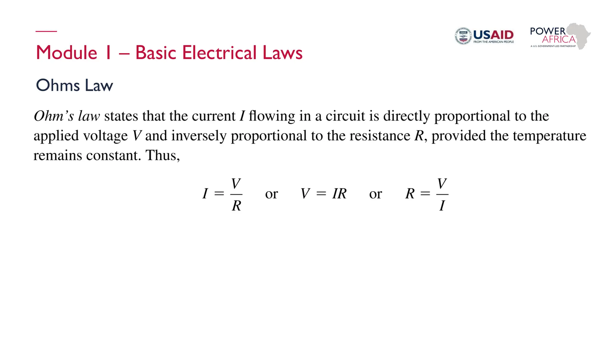
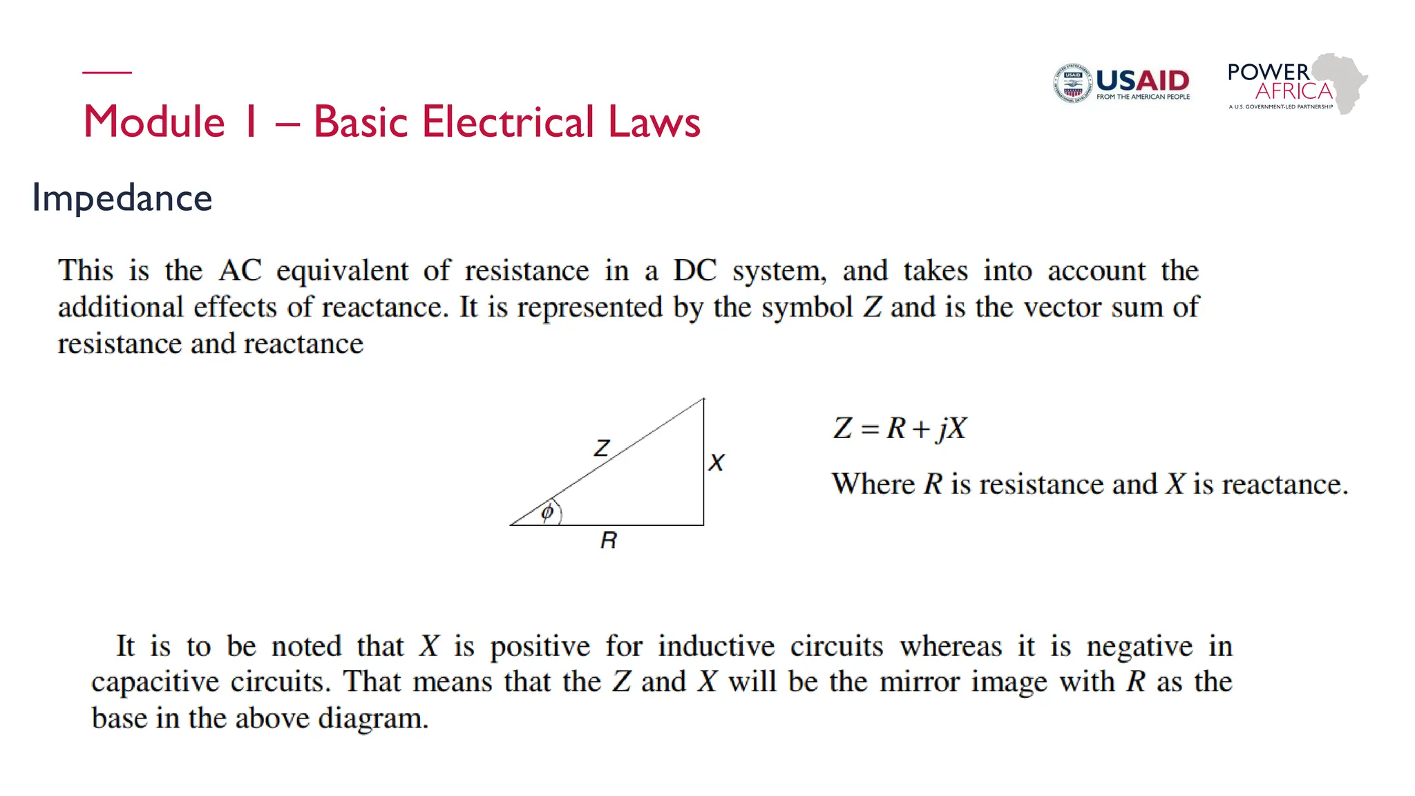
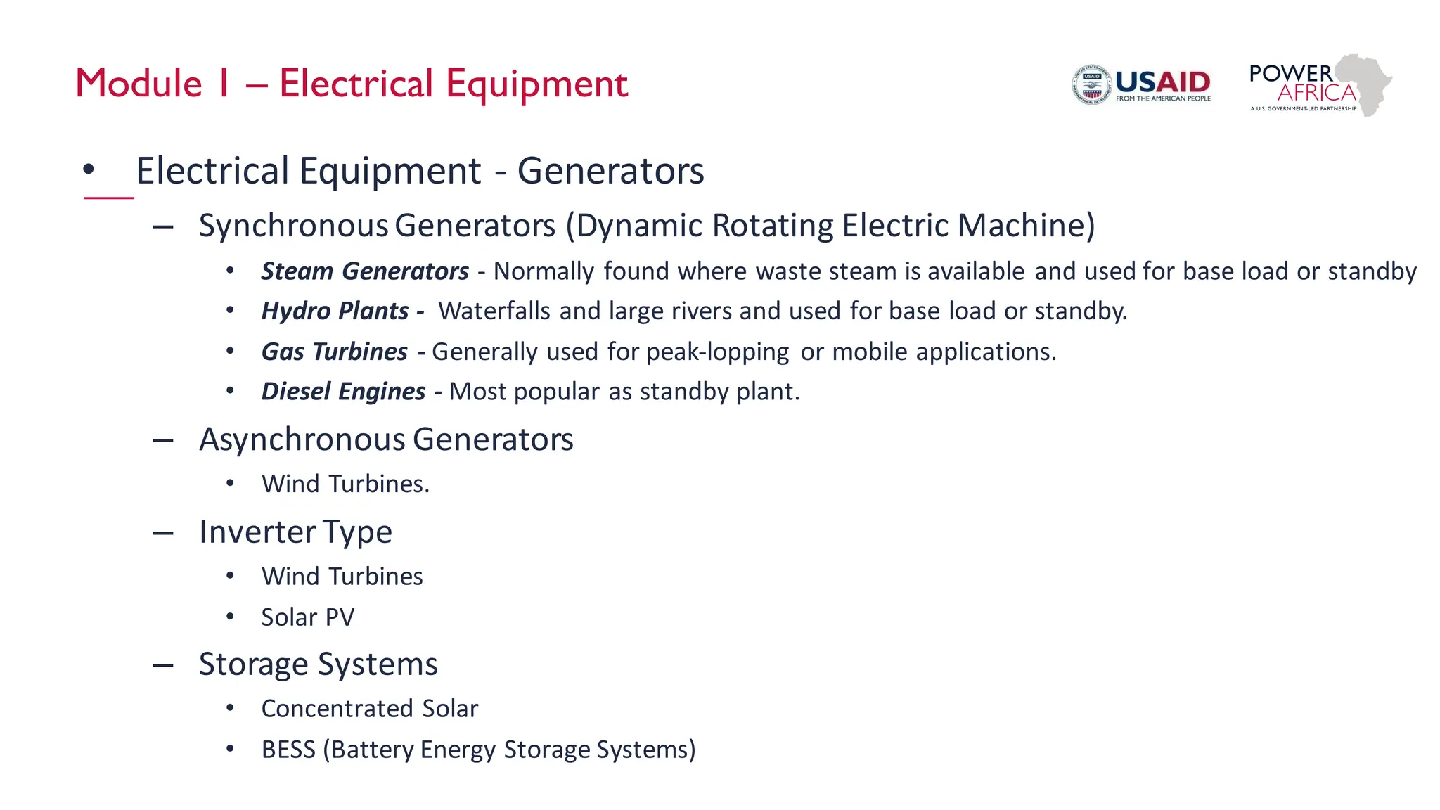
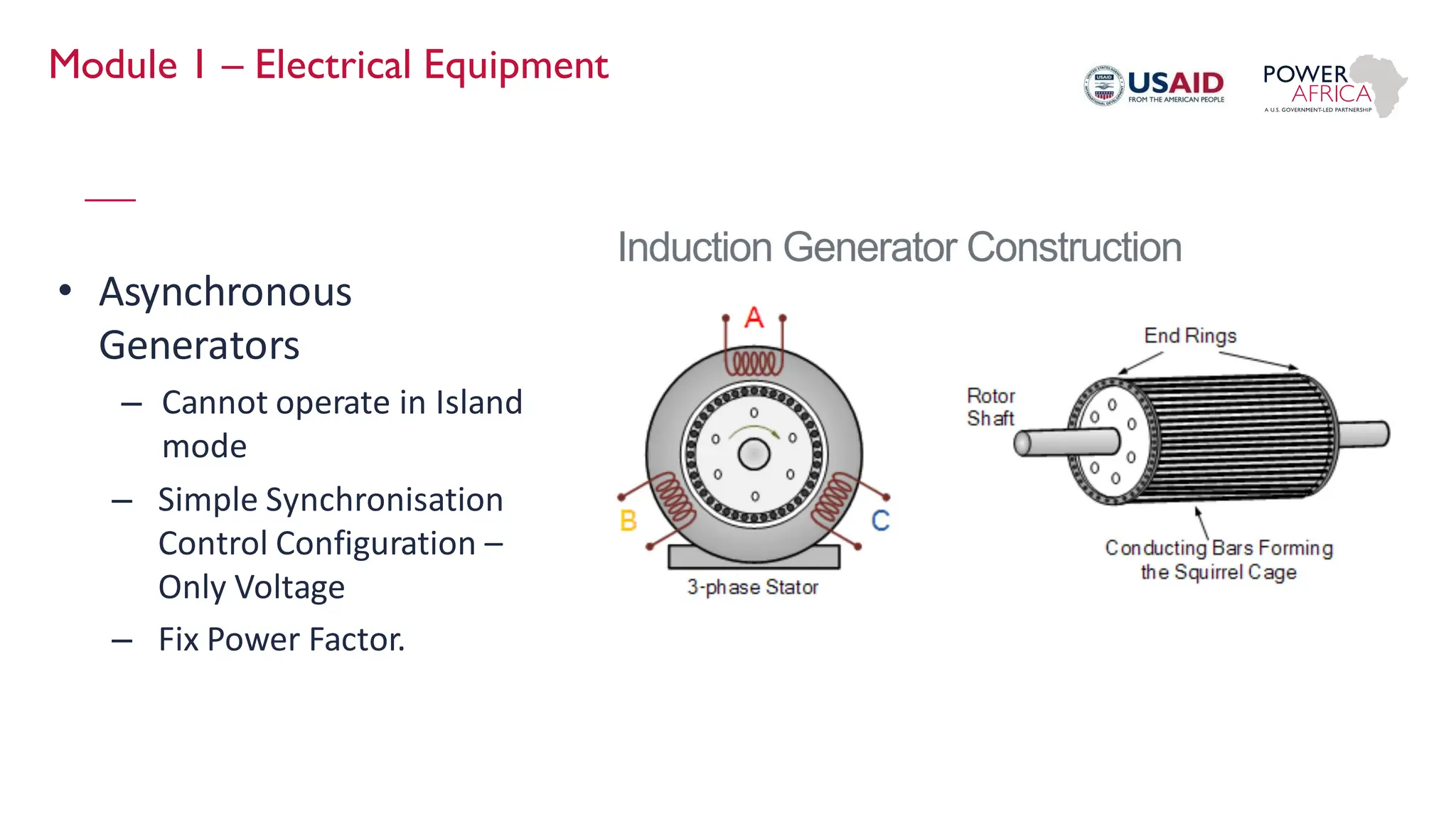
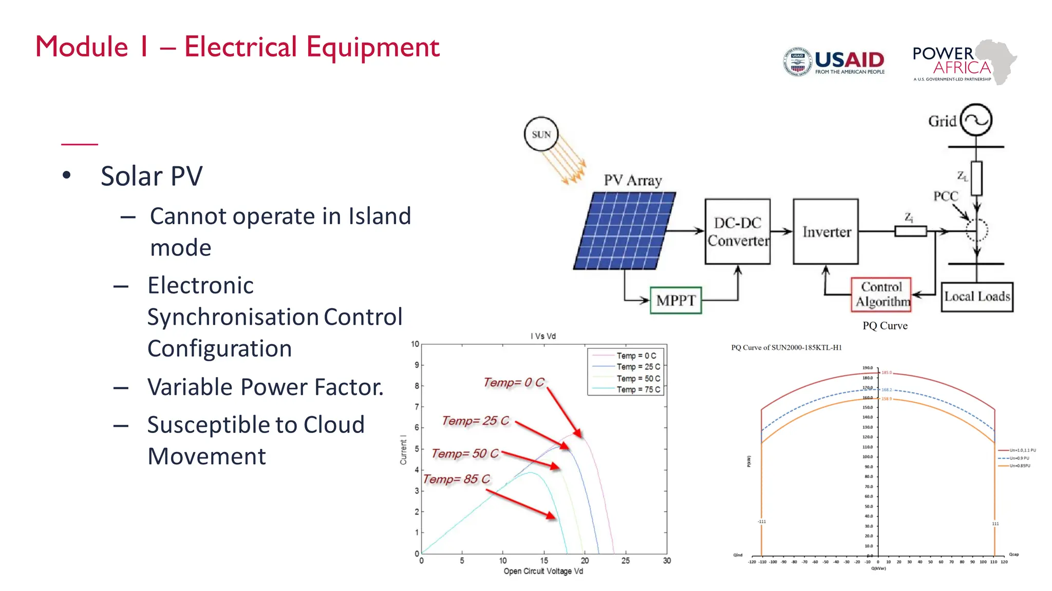
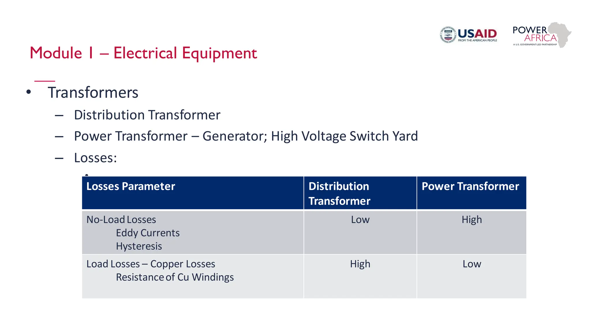
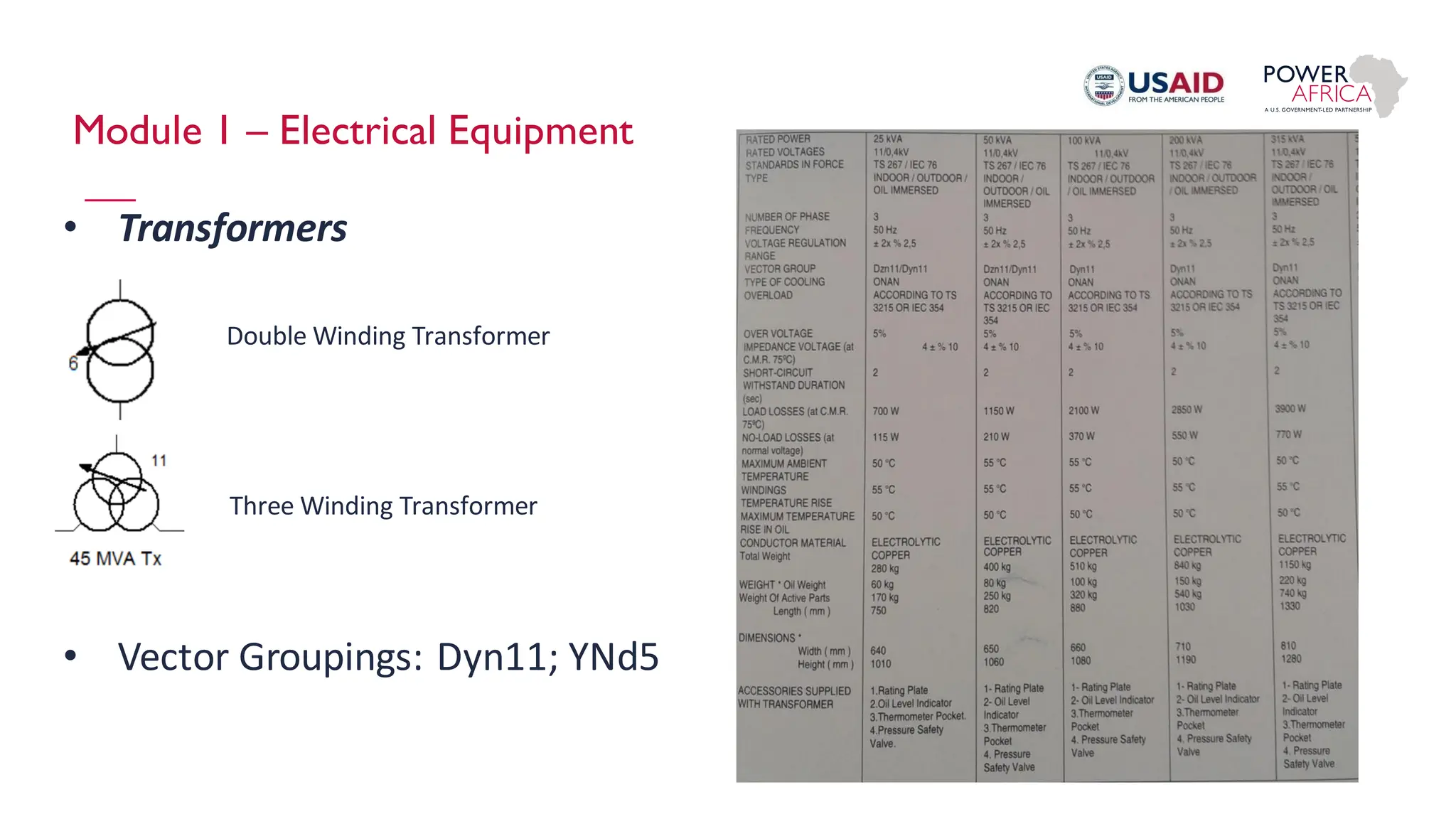
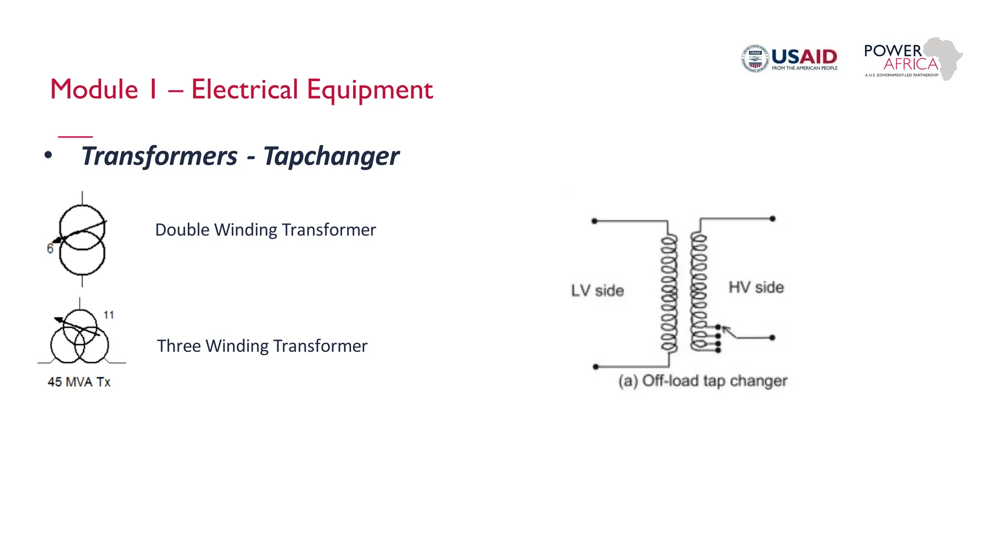
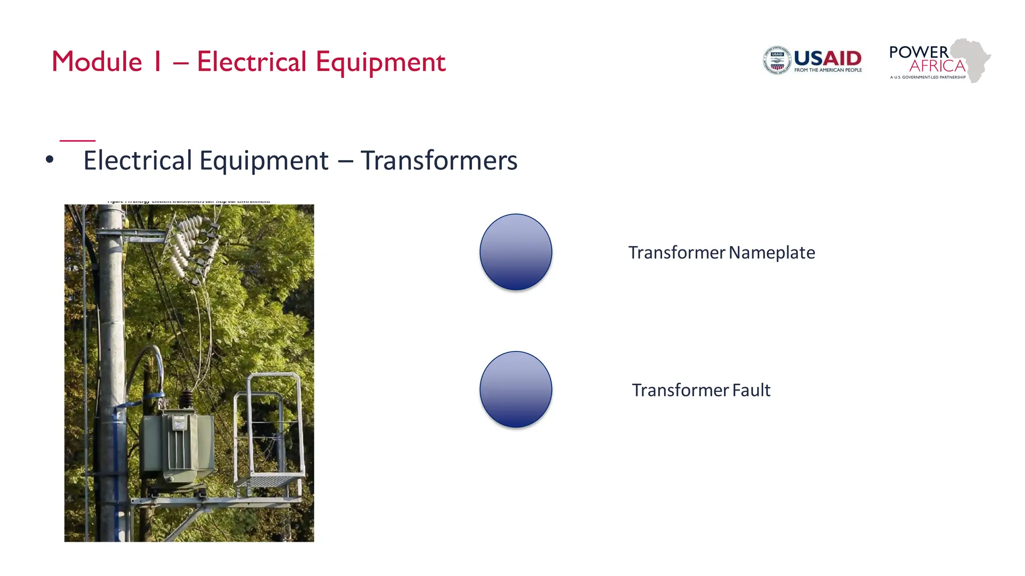
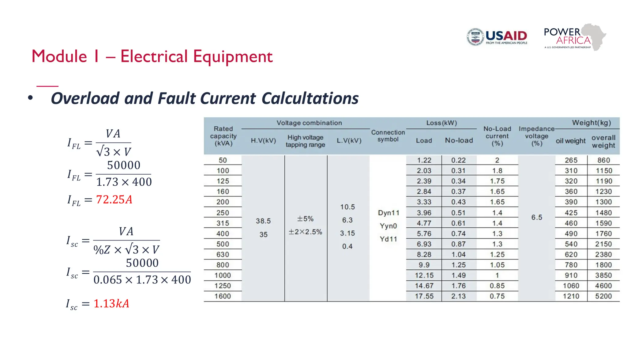
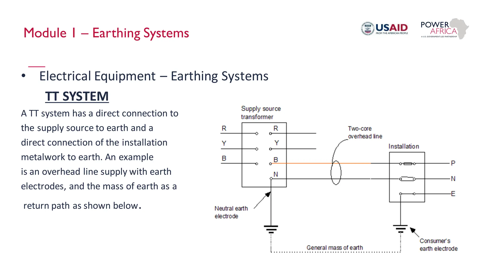
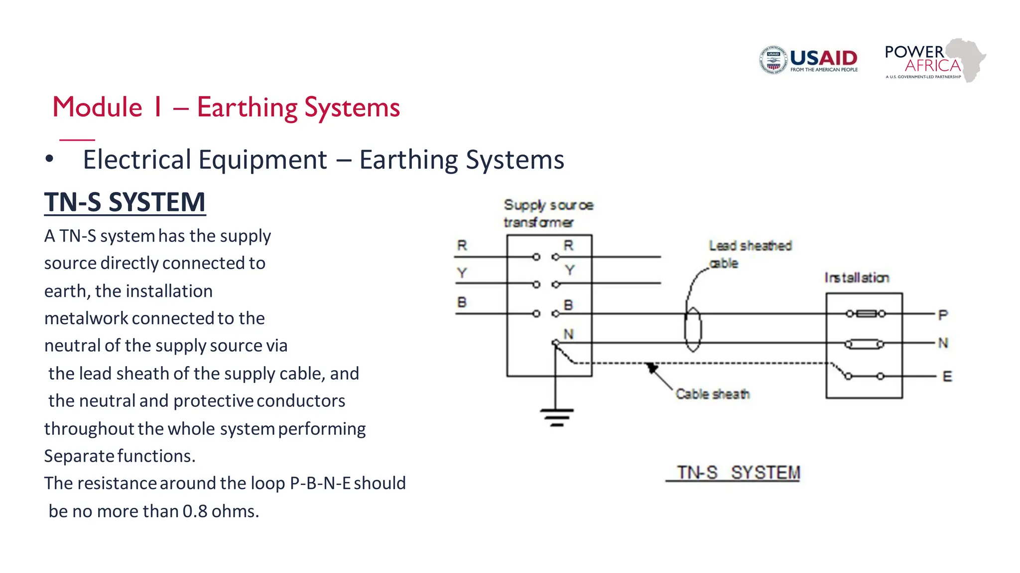
Module 1 – Basic
Electrical Knowledge
Oct 2021
Module 1 – Discussion Topics
1. Basic Electrical Laws
2. Description of Electrical Equipment in a Typical Distribution and
Reticulation Network.
3. Interpreting Nameplate Data
4. Interpreting Equipment Manuals
5. Standard Electrical Calculations to Determine Equipment Ratings
6. Building Blocks of a Medium and LowVoltage Network.
7. Practical Session
8. Work Place Safety
Module 1 – Basic Electrical Laws
Ohms Law
Module 1 – Basic Electrical Laws
Impedance
Module 1 – Basic Electrical Laws
Reactance
Module 1 – Basic Electrical Laws
Power Equations
Losses Equation
Module 1 – Basic Electrical Laws
Power Equations
Resistor Circuit
E=RxI
InductorCircuit Capacitor Circuit
Module 1 – Basic Electrical Laws
Power Equations
Resistor Circuit
E=RxI
InductorCircuit Capacitor Circuit
Module 1 – Basic Electrical Laws
Power Factor
Module 1 – Basic Electrical Laws
Power Factor
Module 1 – Basic Electrical Laws
Power Factor
Module 1 – Basic Electrical Laws
Power Factor – Practical Example
Module 1 – Basic Electrical Laws
Power Factor – Practical Example
Module 1 – Electrical Equipment
• Electrical Equipment - Generators
– SynchronousGenerators (Dynamic Rotating Electric Machine)
• Steam Generators - Normally found where waste steam is available and used for base load or standby
• Hydro Plants - Waterfalls and large rivers and used for base load or standby.
• Gas Turbines - Generally used for peak-lopping or mobile applications.
• Diesel Engines - Most popular as standby plant.
– Asynchronous Generators
• Wind Turbines.
– Inverter Type
• Wind Turbines
• Solar PV
– Storage Systems
• Concentrated Solar
• BESS (Battery Energy Storage Systems)
Module 1 – Electrical Equipment
– Synchronous Generators
• Can operate in Island mode
• Adjust Speed and Voltage levels for
variable loads
• Can be set as Variable and constant
power factor.
• Complex Synchronisation Control
Configuration (Voltage, Phase Angle,
Frequency)
Synchronous Generators
Capability Curve
Module 1 – Electrical Equipment
• Asynchronous
Generators
– Cannot operate in Island
mode
– Simple Synchronisation
Control Configuration –
Only Voltage
– Fix Power Factor.
Module 1 – Electrical Equipment
Torque - Speed Curve
Module 1 – Electrical Equipment
• Wind Turbines (DFIG)
– Cannot operate in Island
mode
– Simple Synchronisation
Control Configuration –
Only Voltage
– Fix Power Factor.
Module 1 – Electrical Equipment
• Wind Turbine (Inverter Type)
– Cannot operate in Island
mode
– Electronic
SynchronisationControl
Configuration
– Variable Power Factor.
Module 1 – Electrical Equipment
• Solar PV
– Cannot operate in Island
mode
– Electronic
SynchronisationControl
Configuration
– Variable Power Factor.
– Susceptible to Cloud
Movement
Module 1 – Electrical Equipment
Solar PV
Electrical Equipment
Module 1 – Electrical Equipment
Solar PV
• Need Spinning Reserve to
accommodate cloud movement
Module 1 – Electrical Equipment
Concentrated Solar
• Temperature of fluid around1000ᵒC
• Heat exchangerto heat water to
superheated steam.
• $5000-10000/kWe
Module 1 – Electrical Equipment
• Electrical Equipment – Power Lines & Cables
– Different Type of Bare Conductor
• ACSR – Aluminium Conductor Steal Reinforced
• AAC – All Aluminium Conductor
• AAAC – All Aluminium Alloy Conductors Hydro Plants
ACSR AAR/AAAR
Module 1 – Electrical Equipment
• Electrical Equipment – Power Lines
Module 1 – Electrical Equipment
• Electrical Equipment – Power Lines & Cables
– Arial Bundle Conductor(ABC)
• German Design
• French Design
Module 1 – Electrical Equipment
– Arial Bundle ConductorLine Materials
Module 1 – Electrical Equipment
• Transformers
– Distribution Transformer
– Power Transformer – Generator; High Voltage Switch Yard
– Losses:
•
Losses Parameter Distribution
Transformer
Power Transformer
No-LoadLosses
Eddy Currents
Hysteresis
Low High
Load Losses – Copper Losses
Resistanceof Cu Windings
High Low
Module 1 – Electrical Equipment
• Transformers
• Vector Groupings: Dyn11; YNd5
Double Winding Transformer
Three Winding Transformer
Module 1 – Electrical Equipment
• Transformers - Tapchanger
Double Winding Transformer
Three Winding Transformer
Module 1 – Electrical Equipment
• Electrical Equipment – Transformers
TransformerFault
TransformerNameplate
Module 1 – Electrical Equipment
• Overload and Fault Current Calcultations
𝐼𝐹𝐿 =
𝑉𝐴
√3 × 𝑉
𝐼𝑠𝑐 =
50000
0.065 × 1.73× 400
𝐼𝐹𝐿 = 72.25𝐴
𝐼𝑠𝑐 =
𝑉𝐴
%𝑍 × √3 × 𝑉
𝐼𝐹𝐿 =
50000
1.73 × 400
𝐼𝑠𝑐 = 1.13𝑘𝐴
Module 1 – Earthing Systems
• Electrical Equipment – Earthing Systems
These have been designated in the IEE Regulations using the letters: T, N, C and S.
These letters stand for:
T - terre (French for earth) and meaning a direct connection to earth.
N - neutral
C - combined
S - separate.
When these letters are grouped, they form the classification of a type of system.
Module 1 – Earthing Systems
• Electrical Equipment – Earthing Systems
TT SYSTEM
A TT system has a direct connection to
the supply source to earth and a
direct connection of the installation
metalwork to earth. An example
is an overhead line supply with earth
electrodes, and the mass of earth as a
return path as shown below.
Module 1 – Earthing Systems
• Electrical Equipment – Earthing Systems
TN-S SYSTEM
A TN-S systemhas the supply
source directly connected to
earth, the installation
metalwork connectedto the
neutral of the supply source via
the lead sheath of the supply cable, and
the neutral and protectiveconductors
throughoutthe whole systemperforming
Separatefunctions.
The resistancearound the loop P-B-N-Eshould
be no more than 0.8 ohms.
Module 1 – Earthing Systems
• Electrical Equipment – Earthing Systems
TN-S SYSTEM
A TN-C-S systemis as the TN-S but the
supply cable sheath is also the neutral,
i.e. it forms a combined earth/neutral
conductorknown as a PEN
(protectiveearthed neutral)
conductor.
The installationearth and neutral are
separateconductors.
This systemis also known as PME
(protectivemultiple earthing).
The resistancearound the P-B-N-Nloop should be less than 0.35ohms.
THE END

Module 1 - Basic Electricity and Equipments

  • 1.
    Module 1 –Basic Electrical Knowledge Oct 2021
  • 2.
    Module 1 –Discussion Topics 1. Basic Electrical Laws 2. Description of Electrical Equipment in a Typical Distribution and Reticulation Network. 3. Interpreting Nameplate Data 4. Interpreting Equipment Manuals 5. Standard Electrical Calculations to Determine Equipment Ratings 6. Building Blocks of a Medium and LowVoltage Network. 7. Practical Session 8. Work Place Safety
  • 3.
    Module 1 –Basic Electrical Laws Ohms Law
  • 4.
    Module 1 –Basic Electrical Laws Impedance
  • 5.
    Module 1 –Basic Electrical Laws Reactance
  • 6.
    Module 1 –Basic Electrical Laws Power Equations Losses Equation
  • 7.
    Module 1 –Basic Electrical Laws Power Equations Resistor Circuit E=RxI InductorCircuit Capacitor Circuit
  • 8.
    Module 1 –Basic Electrical Laws Power Equations Resistor Circuit E=RxI InductorCircuit Capacitor Circuit
  • 9.
    Module 1 –Basic Electrical Laws Power Factor
  • 10.
    Module 1 –Basic Electrical Laws Power Factor
  • 11.
    Module 1 –Basic Electrical Laws Power Factor
  • 12.
    Module 1 –Basic Electrical Laws Power Factor – Practical Example
  • 13.
    Module 1 –Basic Electrical Laws Power Factor – Practical Example
  • 14.
    Module 1 –Electrical Equipment • Electrical Equipment - Generators – SynchronousGenerators (Dynamic Rotating Electric Machine) • Steam Generators - Normally found where waste steam is available and used for base load or standby • Hydro Plants - Waterfalls and large rivers and used for base load or standby. • Gas Turbines - Generally used for peak-lopping or mobile applications. • Diesel Engines - Most popular as standby plant. – Asynchronous Generators • Wind Turbines. – Inverter Type • Wind Turbines • Solar PV – Storage Systems • Concentrated Solar • BESS (Battery Energy Storage Systems)
  • 15.
    Module 1 –Electrical Equipment – Synchronous Generators • Can operate in Island mode • Adjust Speed and Voltage levels for variable loads • Can be set as Variable and constant power factor. • Complex Synchronisation Control Configuration (Voltage, Phase Angle, Frequency)
  • 16.
  • 17.
    Module 1 –Electrical Equipment • Asynchronous Generators – Cannot operate in Island mode – Simple Synchronisation Control Configuration – Only Voltage – Fix Power Factor.
  • 18.
    Module 1 –Electrical Equipment Torque - Speed Curve
  • 19.
    Module 1 –Electrical Equipment • Wind Turbines (DFIG) – Cannot operate in Island mode – Simple Synchronisation Control Configuration – Only Voltage – Fix Power Factor.
  • 20.
    Module 1 –Electrical Equipment • Wind Turbine (Inverter Type) – Cannot operate in Island mode – Electronic SynchronisationControl Configuration – Variable Power Factor.
  • 21.
    Module 1 –Electrical Equipment • Solar PV – Cannot operate in Island mode – Electronic SynchronisationControl Configuration – Variable Power Factor. – Susceptible to Cloud Movement
  • 22.
    Module 1 –Electrical Equipment Solar PV Electrical Equipment
  • 23.
    Module 1 –Electrical Equipment Solar PV • Need Spinning Reserve to accommodate cloud movement
  • 24.
    Module 1 –Electrical Equipment Concentrated Solar • Temperature of fluid around1000ᵒC • Heat exchangerto heat water to superheated steam. • $5000-10000/kWe
  • 25.
    Module 1 –Electrical Equipment • Electrical Equipment – Power Lines & Cables – Different Type of Bare Conductor • ACSR – Aluminium Conductor Steal Reinforced • AAC – All Aluminium Conductor • AAAC – All Aluminium Alloy Conductors Hydro Plants ACSR AAR/AAAR
  • 26.
    Module 1 –Electrical Equipment • Electrical Equipment – Power Lines
  • 27.
    Module 1 –Electrical Equipment • Electrical Equipment – Power Lines & Cables – Arial Bundle Conductor(ABC) • German Design • French Design
  • 28.
    Module 1 –Electrical Equipment – Arial Bundle ConductorLine Materials
  • 30.
    Module 1 –Electrical Equipment
  • 31.
    Module 1 –Electrical Equipment • Transformers – Distribution Transformer – Power Transformer – Generator; High Voltage Switch Yard – Losses: • Losses Parameter Distribution Transformer Power Transformer No-LoadLosses Eddy Currents Hysteresis Low High Load Losses – Copper Losses Resistanceof Cu Windings High Low
  • 32.
    Module 1 –Electrical Equipment • Transformers • Vector Groupings: Dyn11; YNd5 Double Winding Transformer Three Winding Transformer
  • 33.
    Module 1 –Electrical Equipment • Transformers - Tapchanger Double Winding Transformer Three Winding Transformer
  • 34.
    Module 1 –Electrical Equipment • Electrical Equipment – Transformers TransformerFault TransformerNameplate
  • 35.
    Module 1 –Electrical Equipment • Overload and Fault Current Calcultations 𝐼𝐹𝐿 = 𝑉𝐴 √3 × 𝑉 𝐼𝑠𝑐 = 50000 0.065 × 1.73× 400 𝐼𝐹𝐿 = 72.25𝐴 𝐼𝑠𝑐 = 𝑉𝐴 %𝑍 × √3 × 𝑉 𝐼𝐹𝐿 = 50000 1.73 × 400 𝐼𝑠𝑐 = 1.13𝑘𝐴
  • 36.
    Module 1 –Earthing Systems • Electrical Equipment – Earthing Systems These have been designated in the IEE Regulations using the letters: T, N, C and S. These letters stand for: T - terre (French for earth) and meaning a direct connection to earth. N - neutral C - combined S - separate. When these letters are grouped, they form the classification of a type of system.
  • 37.
    Module 1 –Earthing Systems • Electrical Equipment – Earthing Systems TT SYSTEM A TT system has a direct connection to the supply source to earth and a direct connection of the installation metalwork to earth. An example is an overhead line supply with earth electrodes, and the mass of earth as a return path as shown below.
  • 38.
    Module 1 –Earthing Systems • Electrical Equipment – Earthing Systems TN-S SYSTEM A TN-S systemhas the supply source directly connected to earth, the installation metalwork connectedto the neutral of the supply source via the lead sheath of the supply cable, and the neutral and protectiveconductors throughoutthe whole systemperforming Separatefunctions. The resistancearound the loop P-B-N-Eshould be no more than 0.8 ohms.
  • 39.
    Module 1 –Earthing Systems • Electrical Equipment – Earthing Systems TN-S SYSTEM A TN-C-S systemis as the TN-S but the supply cable sheath is also the neutral, i.e. it forms a combined earth/neutral conductorknown as a PEN (protectiveearthed neutral) conductor. The installationearth and neutral are separateconductors. This systemis also known as PME (protectivemultiple earthing). The resistancearound the P-B-N-Nloop should be less than 0.35ohms.
  • 40.