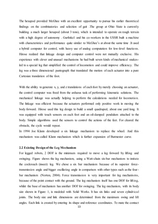
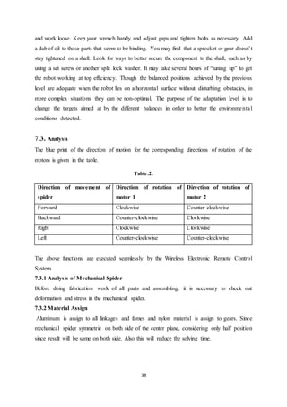
SlideShare a Scribd company logo
1
MECHANICAL SPIDER ROBOT BY
“KLANN MECHANISM”
By
AMBIKESH KR. GUPTA (1316140805)
AMIT AGARWAL (1316140806)
ANKIT SINGH (1316140810)
KULDEEP SINGH (1316140827)
Under the Supervision of
Ms. PARUL YADAV
(Assistant Professor)
Submitted to the Department of Mechanical Engineering
in partial fulfillment of the requirements
for the degree of
Bachelor of Technology
In
Mechanical Engineering
Krishna Engineering College (161)
Dr. APJ Abdul Kalam Technical University
April, 2017
2
CERTIFICATE
This is to certify that Project Report entitled “Mechanical Spider Robot by Klann
Mechanism” which is submitted by Ambikesh Kr. Gupta, Amit Agarwal, Ankit Singh and
Kuldeep Singh in partial fulfillment of the requirement for the award of degree B. Tech. in
Department of Mechanical Engineering of Dr. A.P.J. Abdul Kalam Technical University,
is a record of the candidate own work carried out by him under my supervision. The matter
embodied in this thesis is original and has not been submitted for the award of any other degree.
Date: Supervisor
3
DECLARATION
I hereby declare that this submission is my own work and that, to the best of my knowledge
and belief, it contains no material previously published or written by another person nor
material which to a substantial extent has been accepted for the award of any other degree or
diploma of the university or other institute of higher learning, except where due
acknowledgment has been made in the text.
Name Roll No. Signature Date
Ambikesh Kr. Gupta 1316140805
Amit Agarwal 1316140806
Ankit Singh 1316140810
Kuldeep Singh 1316140827
4
ACKNOWLEDGEMENT
It gives us a great sense of pleasure to present the report of the B. Tech Project undertaken
during B. Tech. Final Year. We owe special debt of gratitude to Professor Parul Yadav,
Department of Mechanical Engineering, Krishna Engineering College, Ghaziabad for his
constant support and guidance throughout the course of our work. Her sincerity, thoroughness
and perseverance have been a constant source of inspiration for us. It is only his cognizant
efforts that our endeavors have seen light of the day.
We also take the opportunity to acknowledge the contribution of Professor Pawan Mishra
Head Project coordinator Department of Mechanical Engineering, Krishna Engineering
College, Ghaziabad for his full support and assistance during the development of the project.
We also do not like to miss the opportunity to acknowledge the contribution of all faculty
members of the department for their kind assistance and cooperation during the development
of our project. Last but not the least, we acknowledge our friends for their contribution in the
completion of the project.
Signature: Signature:
Name : Ambikesh kr. Gupta Name : Amit Agarwal
Roll No. : 1316140805 Roll No. : 1316140806
Date : Date :
Signature: Signature:
Name : Ankit Singh Name : Kuldeep Singh
5
Roll No. : 1316140810 Roll No. : 1316140827
Date : Date :
LIST OF ABBREVIATIONS
DOF Degree of Freedom
MSKM Mechanical Spider by Klann Mechanism
RPM Rotation per Minute
PTFE Polytetrafluorethylene
SAN Styrene acrylonitrile
6
ABSTRACT
As the wheels are ineffective on rough and rocky areas, therefore robot with legs provided with
Klann mechanism is beneficial for advanced walking vehicles. It can step over curbs, climb
stairs or travel areas that are currently not accessible with wheels. The most important benefit
of this mechanism is that, it does not require microprocessor control or large amount of actuator
mechanisms. In this mechanism links are connected by pivot joints and convert the rotating
motion of the crank into the movement of foot similar to that of animal walking. The
proportions of each of the links in the mechanism are defined to optimize the linearity of the
foot for one-half of the rotation of the crank. The remaining rotation of the crank allows the
foot to be raised to a predetermined height before returning to the starting position and
repeating the cycle. Two of these linkages coupled together at the crank and one-half cycle out
of phase with each other will allow the frame of a vehicle to travel parallel to the ground. This
project is useful in hazardous material handling, clearing minefields, or secures an area without
putting anyone at risk. The military, law enforcement, Explosive Ordinance Disposal units,
and private security firms could also benefit from applications of mechanical spider. It would
perform very well as a platform with the ability to handle stairs and other obstacles to wheeled
or tracked vehicles.
The goal for this project is to create an eight-legged robot to test new walking algorithm. We
loosely based our design on spider because there has an advanced way in robotics on octopedal
locomotion. Hopefully algorithm develops will be of use to robotics community and in future
society.
7
TABLE OF CONTENT
1. Introduction
1.1 Why Klann Mechanism ?
1.2 Background
1.3 Origin
1.4 Burmester Curve
1.5 Overview
1.6 Objective
2. Literature Survey
2.1 History of legged mechanism
2.2 Existing design of the leg mechanism
2.3 Mechanical design of quadruped robot
2.4 Theo Jansen mechanism for climbing over bumps
2.5 Under water autonomous walking robot
3. Mechanism
3.1 Overview
3.2 Klann mechanism
3.3 Jansen linkage mechanism
4. Design and Calculation
4.1 Calculation of dimension of linkage
4.2 Testing of dimension
4.3 Calculation of degree of freedom
4.4 Calculation of dimension of gear
4.4.1 Gear nomenclature
4.4.2 Calculation of dimension of larger gear
4.4.3 Calculation of dimension of smaller gear
4.5 Determination of dimension of base plate
4.6 Design of parts and assembly
4.6.1 Leg
4.6.2 Assembly view
8
5. Components
5.1 Frame and base plate
5.2 Aluminium bars
5.2.1 Properties of Aluminium
5.2.2 Advantage of Aluminium
5.3 Electric motor
5.3.1 Features of the electric motor
5.4 Gears
5.4.1 Plastic gear material
5.5 Shaft
5.6 Legs
5.7 Linkage
5.7.1 Klann linkage
5.8 Control system
5.8.1 RF Transmitter
5.8.2 RF Receiver
5.9 Batteries
6. Fabrication
6.1 Soldering
6.2 Drilling
7. Construction and working
7.1 Construction
7.2 Working
7.3 Analysis
8. Merits of mechanical mover
8.1 Merits of Klann mechanism
8.2 Advantage of Klann mechanism
9. Cost estimation
10. Conclusion
11. Bibliography
11.1 Reference
11.2 Websites
9
CHAPTER-1
INTRODUCTION
1.1 Why Klann Mechanism?
The main advantage of Klann mechanism robots is their ability to access places impossible for
wheeled robots. By copying to the physical structure of legged animals, it may be possible to
improve the performance of mobile robots. To provide more stable and faster walking,
scientists and engineers can implement the relevant biological concepts in their design. The
most forceful motivation for studying Klann mechanism robots is
 To give access to places which are dirty.
 To give access to places those are dangerous.
Job which are highly difficult legged robots can be used for rescue work after earthquakes and
in hazardous places such as the inside of a nuclear reactor, giving biologically inspired
autonomous legged robots great potential. Low power consumption and weight are further
advantages of walking robots, so it is important to use the minimum number of actuators. In
this context, an objective is set in this project to develop an eight- legged mobile robot whose
structure is based on the biomechanics of insects.
1.2. Background
Since time unknown, man’s fascination towards super-fast mobility has been unquestionable.
His never ending quest towards lightning fast travel has gained pace over the past few decades.
Now, with every passing day, man is capable of covering longer distances in relatively shorter
duration of time. Today’s automobiles are beasts on wheels which are designed for speed and
comfort.
However, most of today’s automobiles are limited to roads or plain terrains. Even the off-road
vehicles are of no use when the land is too rough. Needless to say, no vehicle can climb
mountains.
This is because all automobiles depend on rubber wheels which fare better only on roads. Man,
who himself depends, on legs can travel on rocky terrains and climb mountains, but such
journeys are never comfortable.
Thus naturally the solution can be seen as an automobile which rests on and moves with legs.
Simple, it may sound but the problems in building a working model are many. The most
10
troublesome part is powering the gait of the legs. Rotation of wheels in wheeled vehicles is
powered by an engine or electric motors. Unlike wheels, legs move in an acute reciprocating
movement. This is practically tough.
This is where Klann Mechanism pitches in. It converts rotary action directly into linear
movement of a legged animal. Vehicles using this mechanism can travel on any type of surface.
Also, they do not require heavy investments in road infrastructure.
1.3. Origin
The Klann linkage is a planar mechanism designed to simulate the gait of legged animal and
function as a wheel replacement. The linkage consists of the frame, a crank, two grounded and
two couplers all connected by pivot joints. It was developed by Joe Klann in 1994 as an
expansion of Burmester curves which are used to develop four-bar double-rocker linkages such
as harbor crane booms. It is categorized as a modified Stephenson type III kinematic chain.
The proportions of each of the links in the mechanism are defined to optimize the linearity of
the foot for one-half of the rotation of the crank. The remaining rotation of the crank allows the
foot to be raised to a predetermined height before returning to the starting position and
repeating the cycle. Two of these linkages coupled together at the crank and one-half cycle out
of phase with each other will allow the frame of a vehicle to travel parallel to the ground.
The Klann linkage provides many of the benefits of more advanced walking vehicles without
some of their limitations. It can step over curbs, climb stairs, or travel into areas that are
currently not accessible with wheels but does not require microprocessor control or multitudes
of actuator mechanisms. It fits into the technological space between these walking devices and
axle-driven wheels.
1.4. Burmester Curve
Burmester theory is named after Ludwig Burmester (1840–1927). Burmester introduced
geometric techniques for synthesis of linkages in the late 19th century. His approach was to
compute the geometric constraints of the linkage directly from the inventor's desired movement
for a floating link. From this point of view a four-bar linkage is a floating link that has two
points constrained to lie on two circles.
Burmester began with a set of locations, often called poses, for the floating link, which are
viewed as snapshots of the constrained movement of this floating link in the device that is to
be designed. The design of a crank for the linkage now becomes finding a point in the moving
11
floating link that when viewed in each of these specified positions has a trajectory that lies on
a circle. The dimension of the crank is the distance from the point in the floating link, called
the circling point, to the canter of the circle it travels on, called the center point. Two cranks
designed in this way form the desired four-bar linkage.
This formulation of the mathematical synthesis of a four-bar linkage and the solution to the
resulting equations is known as Burmester Theory. The approach has been generalized to the
synthesis of spherical and spatial mechanisms.
1.5. Overview
It is the fact that the wheels are ineffective on rough and rocky areas. Therefore vehicle with
legs provided with Klann mechanism is beneficial for advanced walking vehicles. It can step
over curbs, climb stairs or travel areas that are currently not accessible with wheels. The most
important benefit of this mechanism is that, it does not require microprocessor control or large
amount of actuator mechanisms. In this mechanism links are connected by pivot joints and
convert the rotating motion of the crank into the movement of foot similar to that of animal
walking.
The proportions of each of the links in the mechanism are defined to optimize the linearity of
the foot for one-half of the rotation of the crank. The remaining rotation of the crank allows the
foot to be raised to a predetermined height before returning to the starting position and
repeating the cycle.
This project is useful in hazardous material handling, clearing minefields, or secures an area
without putting anyone at risk .The military, Explosive Ordinance Disposal units, and security
system could also benefit from applications of mechanical spider. It would perform very well
as a platform with the ability to handle stairs and other obstacles.
1.6. Objective
Our project, “Design and Fabrication of Mechanical Mover using Klann Mechanism”, is to
demonstrate the working of Klann Mechanism through a simple walking robot.
A normal robot (or vehicle) can move only forward and backward direction. By using Klann
Mechanism the vehicle can able to move in one plane along different direction. The movement
of the kinematic linkage is done by the use of electric motors.
12
CHAPTER-2
LITERATURE SURVEY
2.1 History of Legged Mechanism
The scientific study of legged locomotion began just very a century ago when Leland Stanford,
then governor of California, commissioned Edward Muyridge to find out whether or not a
trotting horse left the ground with all four feet at the same time. Stanford had wagered that it
never did. After Muybridge proved him wrong with a set of stop motion photographs that
appeared in Scientific American in 1878, Muybridge went on to document the walking and
running behavior of over 40 mammals, including humans. His photographic data are still of
considerable value and survive as a landmark in locomotion research. The study of machines
that walk also had its origin in Muybridge’s time. An early walking model appeared in about.
It used a linkage to move the body along a straight horizontal path while the feet moved up and
down to exchange support during stepping. The linkage was originally designed by the famous
Russian mathematician Chebyshev some years earlier. During the 80 or 90 years that followed,
workers viewed the task of building walking machines as the task of designing linkages that
would generate suitable stepping motions when driven by a source of power.
Many designs were proposed but the performance of such machines was limited by their fixed
patterns of motion, since they could not adjust to variations in the terrain by placing the feet on
the best footholds. By the late 1950, it had become clear that linkages providing fixed motion
would not suffice and that useful walking machines would need control.
Computer control became an alternative to human control of legged vehicles in the 1970s.
Robert McGhee’s group at the Ohio State University was the first to use this approach
successfully. In 1977 they built an insect like hexapod that could walk with a number of
standard gaits, turn, walk sideways, and negotiate simple obstacles. The computer’s primary
task was to solve kinematic equations in order to coordinate the 18 electric motors driving the
legs. This coordination ensured that the machine’s center of mass stayed over the polygon of
support provided by the feet while allowing the legs to sequence through a gait. The machine
traveled quite slowly, covering several yards per minute. Force and visual sensing provide a
measure of terrain accommodation in later developments.
13
The hexapod provided McGhee with an excellent opportunity to pursue his earlier theoretical
findings on the combinatorics and selection of gait .The group at Ohio State is currently
building a much larger hexapod (about 3 tons), which is intended to operate on rough terrain
with a high degree of autonomy . Gurfinkel and his co-workers in the USSR built a machine
with characteristics and performance quite similar to McGhee’s at about the same time .It used
a hybrid computer for control, with heavy use of analog computation for low-level functions.
Hirose realized that linkage design and computer control were not mutually exclusive. His
experience with clever and unusual mechanisms he had built seven kinds of mechanical snakes-
led to a special leg that simplified the control of locomotion and could improve efficiency. The
leg was a three dimensional pantograph that translated the motion of each actuator into a pure
Cartesian translation of the foot.
With the ability to generate x, y, and z translations of each foot by merely choosing an actuator,
the control computer was freed from the arduous task of performing kinematic solutions. The
mechanical linkage was actually helping to perform the calculations needed for locomotion.
The linkage was efficient because the actuators performed only positive work in moving the
body forward. Hirose used this leg design to build a small quadruped, about one yard long. It
was equipped with touch sensors on each foot and an oil-damped pendulum attached to the
body. Simple algorithms used the sensors to control the actions of the feet. For cleared the
obstacle, the cycle would repeat.
In 1994 Joe Klann developed a six linkage mechanism to replace the wheel. And this
mechanism was called Klann mechanism which is further expansion of Burmester curve.
2.2 Existing Design of the Leg Mechanism
For legged robots, 2 DOF is the minimum required to move a leg forward by lifting and
swinging. Figure shows the leg mechanism, using a Watt-chain six-bar mechanism to imitate
the cockroach (insect) leg. We chose a six bar mechanism because of its superior force-
transmission angle and bigger oscillating angle in comparison with other types such as the four-
bar mechanism (Norton, 2004). Force transmission is very important for leg mechanisms,
because of the point contact with the ground. The leg mechanism itself has one DOF for lifting,
whilst the base of mechanism has another DOF for swinging. The leg mechanism, with its body
size shown in Figure 1, is modeled with Solid Works. It has six links and seven cylindrical
joints. The body size and link dimensions are determined from the maximum swing and lift
angles. Each link is created by entering its shape and reference coordinates. To mate the contact
14
surfaces of the parts, the assembly bar of the assembly mating menu is used. Then the
component is rotated around an axis, specifying the desired axis and rotation for the selected
surfaces.
2.3 Mechanical Design of a Quadruped Robot
It is a quadruped, electrically actuated, walking and wall climbing robot. The trunk consists of
one part only, and the legs are mounted, symmetrically, on the corners of the trunk. Each leg
has three links and three actuated joints connecting these links. Hip horizontal joint is used to
swing the three links of the leg in a plane parallel to the ground while walking, hip vertical
joint, to attach-detach the foot on and from the terrain for swing and support stages,
respectively.
2.4 Theo Jansen Mechanism for Climbing over Bumps
Transporter vehicles have traditionally used wheel Mechanisms like cars and trains. Wheels
are ideally suited for movement without vertical fluctuations of the body, and tires with inner
rubber tubes absorb shock from a rugged road. Onthe other hand, biologically-inspired robotics
learn mobile flexibility from the morphology of multiple legs and their coordination .Good
examples of this are arthropods, like spiders, and the robots are conventionally designed with
actuators placed in every joint. In such implementation, robots are good tools to investigate
how an animal moves, but they are unable to be a substitute principle for wheels because they
don’t much take into account the maximum load capacity. Joint’s actuators promise mobile
flexibility, while the Actuator’s torque performance impacts on the toughness of the robot’s
body. Therefore, in the design of disaster robots, which need to move on rubble and carry
rescue devices, continuous tracks or crawlers are popular. Theo Jensen a Dutch kinetic artist
who has attempted to create a bridge between art and engineering by focusing on biological
nature, proposed a linkage mechanism to mimic the skeleton of animal legs. This is called
“Theo Jansen mechanism,” and provides the animal with a means of moving in a fluid manner.
Interestingly, his artificial animals require no electric power for actuators, and do work by weak
wind power to drive the gaits of multiple legs through a transformation of internal cyclic motion
to an elliptical orbit of the legs.
15
Fig.1. Theo Jansen Mechanism
2.5 Use of Klann mechanism in underwater autonomous walking robots
A low-cost, biologically inspired underwater walking robot has been designed and built to
covertly explore the seabed and to determine properties of submerged objects in obscure and
inaccessible underwater locations. Adopting legged locomotion for traversing the seabed has a
number of operational advantages; firstly, the platform can maintain its position without
expending energy; secondly, the typically unstructured terrain of the sea bed can be scaled
efficiently, and thirdly, movement generates a low acoustic signature which, for applications
such as mine clearance or littoral Warfare would be beneficial.
2.6 Summary of Literature Review
Literature review reveals that Klann Mechanism robots have ability to access places which are
impossible for wheeled robots. By copying to the physical structure of legged animals, it may
be possible to improve the performance of the mobile robots. By implementing relevant
biological concepts in the design, more stable and faster walking robots could be developed.
Based on the results of literature review, an attempt is made in this project to develop an eight
legged Klann mechanism spider robot.
16
CHAPTER-3
MECHANISM
3.1. Overview
A six bar linkage is a one degree-of-freedom mechanism that is constructed from six links and
seven joints. An example is the Klann linkage used to drive the legs of a walking machine.
In general, each joint of a linkage connects two links, and a binary link supports two joints. If
we consider a hexagon to be constructed from six binary links with six of the seven joints
forming its vertices, then, the seventh joint can be added to connect two sides of the hexagon
to forming a six-bar linkage with two ternary joints. This type of six-bar linkage is said to have
the Watt topology.
A six-bar linkage can also be constructed by first assembling five binary links into a pentagon,
which uses five of the seven joints, and then completing the linkage by adding a binary link
that connects two sides of the pentagon. This again creates two ternary links that are now
separated by one or more binary links. This type of six-bar linkage is said to have the
Stephenson topology. The Klann linkage has the Stephenson topology.
The common mechanisms used in kinematic leg movement are Klann linkage mechanism and
Jansen linkage mechanism. Both will operate in a single plane provided a constant axle height,
use only pivot joints and the rotating crank for input.
3.2. Klann Mechanism
The Klann linkage is a planar mechanism designed to simulate the gait of legged animal and
function as a wheel replacement. The linkage consists of the frame, a crank, two grounded
rockers, and two couplers all connected by pivot joints.
The proportions of each of the links in the mechanism are defined to optimize the linearity of
the foot for one-half of the rotation of the crank. The remaining rotation of the crank allows the
foot to be raised to a predetermined height before returning to the starting position and
repeating the cycle. Two of these linkages coupled together at the crank and one-half cycle out
of phase with each other will allow the frame of a vehicle to travel parallel to the ground.
The Klann linkage provides many of the benefits of more advanced walking vehicles without
some of their limitations. It can step over curbs, climb stairs, or travel into an area that are
currently not accessible with wheels but does not require microprocessor control or multitudes
17
of actuator mechanisms. It fits into the technological space between these walking devices and
axle-driven wheels.
Fig.2. Klann leg mechanism
3.3. Jansen Linkage Mechanism
The foot of a walking mechanism is the part of the mechanism that comes in direct contact with
the ground as indicated. As the crank turns, the foot traces out a cyclical path relative to the
body of the walker; this path is known as the locus. A crank based leg system with the foot,
locus, and crank labeled. The direction of movement of the linkage to the crank and the foot
through the locus are indicated. Additionally, a fixed point in the linkage relative to the body
of the walker is indicated with a black square.
The locus can be divided into four parts: the support, lift, return, and lower phases. Throughout
the support phase, the foot is ideally in contact with the ground. During the lift the foot is
moving toward its maximum height in the locus. During the return, the foot reaches its
maximum height off the ground and moves in the same direction as the body of the walker.
Finally, during the lower the foot descends in height until it makes contact with the ground.
18
Table1: Comparison between Jansen and Klann mechanism
Jansen Linkage Klann Linkage
8 links per leg 120 degrees of crank rotation per
stride. 3 legs will replace a wheel.
Counterclockwise rotation of the crank.
6 links per leg 180 degrees of crank rotation
per stride. 2 legs will replace a wheel.
Clockwise rotation of the crank.
Step height is primarily achieved by a parallel
linkage in the leg that is folded during the cycle
angling the lower portion of the leg.
Step height is achieved by rotating the
connecting arm which is attached to the
crank on one end and the middle of the leg on
the other. It pivots on a grounded rocker.
The eight-bar Jansen linkage evolved through
iterations of a computer program.
A computer program.
The six-bar Klann linkage is an expansion of
the four-bar Burmester linkage developed in
1888 for harbor cranes.
Can walk only on even surfaces and terrain. Can walk on uneven surfaces and terrains.
The number of links in the Jansen mechanism
is more when compared to that in the Klann
mechanism. It is costly.
The number of links in the Klann
mechanism is less when compared to that in
the Jansen mechanism. It is less costly.
19
CHAPTER-4
DESIGN AND CALCULATION
4.1. Testing of Dimensions
Joseph Klann says that all combinations of dimensions calculated by the above method may
not work. There are some sets of dimensions that do not give a smooth gait. So, we decided to
check our dimensions by making a sample. We made samples out of thick paper
Length of upper Rocker arm = 36.4 mm
Length of lower Rocker arm = 26 mm
Length of Connecting arm = 102 mm
Length of Leg = 151 mm
Angle of Connecting arm = 170o
Fig .3. Prototype of Klann Linkage
20
21
4.2. Calculation of DOF
In the design or analysis of a mechanism, one of the most important concerns is the number of
degrees of freedom (also called movability) of the mechanism. It is defined as the number of
input parameters (usually pair variables) which must be independently controlled in order to
bring the mechanism into a useful engineering purpose. It is possible to determine the number
of degrees of freedom of a mechanism directly from the number of links and the number and
types of joints which it includes.
In general, number of degrees of freedom of a mechanism is given by,
n = 3 (l – 1) – 2 j
Where,
n – Degree of freedom
l – Number of links
j – Number of binary joints
This equation is called Kutzbach criterion for the movability of a mechanism having plane
motion.
In Klann Mechanism, for a single leg,
We have, l = 6
j = 7
Hence,
Degree of freedom n = 3(6–1)–2x7
n = 15 – 14
n = 1
4.3. Calculation of Dimensions of Gears
Gears are very important for the movement of our model. Gears transmit power and while
doing so, they reduce the undesirably high rpm delivered by the motors to useable levels.
22
4.3.1. Gear Nomenclature
Number of teeth in larger gear, Z1 = 36
Number of gear in smaller gear, Z2 = 36
Gear Ratio, i = 1
Module, m = 1.5 mm
Speed on smaller gear N1=200rpm
Speed on larger Gear N2=200rpm
Circular pitch Pc=3.4mm
Diametral pitch Pd=0.92mm
Module pitch m=1mm
Peripheral velocity v=0.72m/s
4.3.2. Calculation of Dimensions of Gears
Pitch Diameter, d1 = m.Z1
= 1.5*36
= 54 mm
Diameteral Pitch, DP = Z1/d1
= 36/65
= 0.553 mm-1.
Outside Diameter, Do = (Z1+2)/DP
= (36+2)/0.55
= 69.09 mm.
Addendum, a = 1/DP
= 1/0.55
= 1.81 mm.
Dedendum, d = 1.157/DP
= 1.157/0.92
= 1.9 mm.
Working depth =2.25m
23
=2.25*1.08
=2.43mm
Tooth thickness t =1.5708m
=1.5708*1.08
=1.696mm
Minimum bottom clearance=0.25m
=0.25*1.08
=0.27mm
4.4. Determination of Dimensions of Frame and Base Plate
The base plate carries the whole set up. Also, the frames have holes drilled at certain mounting
points. Any misalignment would result in failure. Hence, the frames and base plate must be
designed in such a way that the movement of linkages is not disrupted.
After carefully considering all the constraints involved, we decided on the set of dimensions
that best suited our needs. The dimensions are:
Length of base plate = 280 mm
Width of base plate = 170 mm
Length of frame = 230 mm
Width of frame = 230mm
Length of the shaft=90mm
Diameter of the shaft=3mm
Number of shaft =4
Thickness of the plate =1mm
4.5. Design of Parts and Assembly
Designing is done by using any modeling software like pro-E, CATIA, etc.
24
4.5.1 Leg
Fig.4. Klann Linkage by Catia software
Fig.5. Klann Linkage assemble view
25
4.5.2. Assembly View
The part drawings of the model are drawn using the modeling software. And then the parts are
assembled using any modeling software and thus the designing of the model is accomplished.
Fig.6.Spider robot assembly view in Catia soft.
Fig.7.Spider robot assembly view in Catia soft.
26
Fig.8.Spider robot assembly view
27
CHAPTER-5
COMPONENTS
5.1. Frames and Base Plate
The model consists of a base plate and four frames which are fixed vertical to the base plate.
The base plate and the frames are made of aluminum.
Aluminium is lightweight, ductile and malleable metal with appearance ranging from silvery
to dull gray, depending on the surface roughness. It is nonmagnetic and does not easily ignite.
A fresh film of aluminium serves as a good reflector (approximately 92%) of visible light and
an excellent reflector (as much as 98%) of medium and far infrared radiation. The yield
strength of pure aluminium is 7–11 MPa, while aluminum alloys have yield strengths ranging
from 200 MPa to 600 MPa.
Aluminium has about one-third the density and stiffness of steel. It
It is easily machined, cast, drawn and extruded. Aluminium atoms are arranged in a face-
centered cubic (fcc) structure. Aluminium has stacking-fault energy of approximately 200
mJ/m2.
Aluminium is a good thermal and electrical conductor, having 59% the conductivity of copper,
both thermal and electrical, while having only 30% of copper's density. Aluminium is capable
of being a superconductor, with a superconducting critical temperature of 1.2 Kelvin and a
critical magnetic field of about 100 gauss.
5.2. Aluminium bars
Aluminium is a silvery white, soft, non-magnetic, ductile metal. Aluminium is the third most
abundant element (after oxygen and silicon), and the most abundant metal in the Earth's crust.
It makes up about 8% by weight of the Earth's solid surface. Aluminium is remarkable for the
metal's low density and for its ability to resist corrosion due to the phenomenon of passivation.
Corrosion resistance can be excellent due to a thin surface layer of aluminium oxide that forms
when the metal is exposed to air, effectively preventing further oxidation. The strongest
aluminium alloys are less corrosion resistant due to galvanic reactions with alloyed copper.
This corrosion resistance is also often greatly reduced by aqueous salts, particularly in the
presence of dissimilar metals. Aluminium is usually alloyed – it is used as pure metal only
when corrosion resistance and/or workability are more important than strength or hardness.
The strength and durability of aluminium alloys vary widely, not only as a result of the
28
components of the specific alloy, but also as a result of heat treatments and manufacturing
processes. The main reason for choosing aluminium is that it is light in weight and light weight
ultimately increases the efficiency of the machine. The low density of aluminium accounts for
it being lightweight but this does not affect its strength.
5.2.2. Properties of Aluminium
Physically, chemically and mechanically aluminum is a metal like steel, brass, copper, zinc,
lead or titanium. It can be melted, cast, formed and machined much like these metals and it
conducts electric current. In fact often the same equipment and fabrication methods are used
as for steel.
Light Weight
Aluminium is a very light metal with a specific weight of 2.7 g/cm3, about a third that of steel.
For example, the use of aluminum in vehicles reduces dead-weight and energy consumption
while increasing load capacity. Its strength can be adapted to the application required by
modifying the composition of its alloys.
Corrosion Resistance
Aluminium naturally generates a protective oxide coating and is highly corrosion resistant.
Different types of surface treatment such as anodizing, painting or lacquering can further
improve this property. It is particularly useful for applications where protection and
conservation are required.
Electrical and Thermal Conductivity
Aluminium is an excellent heat and electricity conductor and in relation to its weight is almost
twice as good a conductor as copper. This has made aluminium the most commonly used
material in major power transmission lines.
Reflectivity
Aluminium is a good reflector of visible light as well as heat, and that together with its low
weight, makes it an ideal material for reflectors in, for example, light fittings or rescue blankets.
Ductility
Aluminium is ductile and has a low melting point and density. In a molten condition it can be
processed in a number of ways. Its ductility allows products of aluminium to be basically
formed close to the end of the product’s design.
29
Impermeable and Odourless
Aluminium foil, even when it is rolled to only 0.007 mm thickness, is still completely
impermeable and lets neither light aroma nor taste substances out. Moreover, the metal itself is
non-toxic and releases no aroma or taste substances which makes it ideal for packaging
sensitive products such as food or pharmaceuticals.
Recyclability
Aluminium is 100 percent recyclable with no downgrading of its qualities. The re-melting of
aluminium requires little energy: only about 5 percent of the energy required to produce the
primary metal initially is needed in the recycling process.
5.2.2. Advantages of Aluminium
1. Aluminium combined with an appropriate alloy ensures steel durability.
2. It may be easily formed in the course of all machining processes, such as rolling,
embossing, forging and die-casting.
3. Aluminium structures have considerable insulation properties securing from air and light
activity
4. Such structures are light, which facilitates assembly and transportation.
5. Aluminium has a natural anti-corrosion layer which efficiently protects from
environmental influences.
6. Aluminium requires little energy required in the processing process. Recycling saves 95%
of the energy.
7. Aluminium as a resource is 100% recyclable.
5.3. Electric Motors
An electric motor is an electrical machine that converts electrical energy into mechanical
energy. Electric motors are used to produce linear or rotary force (torque), and should be
distinguished from devices such as magnetic solenoids and loudspeakers that convert electricity
into motion but do not generate usable mechanical powers. A motor is selected with respect to
the mass of the entire setup.
For smooth movement in all directions, two motors are necessary. Two D.C. motors with rated
speeds of 200 rpm are used. These motors are placed in such a way that each motor drives four
legs. The motors are powered by a rechargeable 12V battery
.
30
5.3.1. Features of the Electric Motor
 200RPM 12V DC motor
 6mm shaft diameter with internal hole
 125gm weight
 Same size motor available in various rpm
 0.5kgcm torque
 No-load current = 60 mA, Load current = 300 mA
5.4. Gears
Gears are very important for transmission. Gears are also useful in speed reduction. Two sets
of gears are used for effective transmission. Each set consists of a smaller gear and two bigger
gears. Smaller gear consists of 36 teeth and a larger gear consists of 60 teeth, thereby giving a
speed reduction ratio of 1.68. The gears are spur gears and are made of nylon plastic gears.
Spur gears or straight-cut gears are the simplest type of gear. They consist of a cylinder or disk
with the teeth projecting radially, and although they are not straight-sided in form (they are
usually of special form to achieve constant drive ratio, mainly involutes, the edge of each tooth
is straight and aligned parallel to the axis of rotation. These gears can be meshed together
correctly only if they are fitted to parallel shafts.
Numerous nonferrous alloys, cast irons, powder-metallurgy and plastics are used in the
manufacture of gears. However, steels are most commonly used because of their high strength-
to-weight ratio and low cost. Plastic is commonly used where cost or weight is a concern. A
properly designed plastic gear can replace steel in many cases because it has many desirable
properties, including dirt tolerance, low speed meshing, the ability to "skip" quite well and the
ability to be made with materials not needing additional lubrication. Manufacturers have
employed plastic gears to reduce costs in consumer items including copy machines, optical
storage devices, cheap dynamos, consumer audio equipment, servo motors, and printer.
5.4.1. Plastic Gear Material
Many different plastics are now used for gearing. Both thermosetting and thermoplastic
material are used, with the latter being by far the most prevalent.
1. Phenolic
Phenolics are invariably compounded with various fillers such as wood flour, mineral, glass,
sisal, chopped cloth, and such lubricants as PTFE (polytetrafluorethylene) and graphite.
31
Phenolics are generally used in applications requiring stability, and when higher temperatures
are encountered.
2. Polyimide
Polyimide is usually 40-65 percent fiber glass reinforced and has good strength retention
when used at high operating temperatures.
3. Nylon
Nylon is a family of thermoplastic polymer. The most widely used of any
molded gearing material is nylon br > 6/6, but nylon 6 and nylon 12 are also used. Some
nylons absorb moisture which may cause dimensional instability. Nylon may be compounded
with various types and amounts of glass reinforcing materials, mineral fillers, and such
lubricants as PTFE and MoS2 (molybdenum disulfide).
4. Acetal
Acetal has a lower water absorption rate than nylon and, therefore, is more stable after
molding or machining. Acetal polymers are used unfilled or filled, with glass and minerals
with and without lubricants, such as PTFE and MoS2, as well as one version with fibrous
PTFE.
5. Polycarbonate
Polycarbonate is generally used with the addition of glass fiber and/or PTFE lubricant and is
a fine, low shrinkage material for producing consistently accurate molded gears.
6. Polyester
Polyesters are both unfilled and with glass fiber, and are finding their way into more markets
as a molded gearing material in competition with nylon and acetal.
7. Polyurethane
Polyurethane is generally noted for its flexibility and, therefore, has the ability to absorb
shock and deaden sound.
8. SAN (Styreneacrylonitrile)
SAN is a stable, low shrinkage material and is used in some lightly loaded gear applications.
9. Polyphenylene Sulfide
When compounded with 40 percent glass fiber with or without internal lubricants, it has been
found in certain gear applications to have much greater strength, even at elevated
temperatures, than most materials previously available.
32
10. Polymer Elastomer
Polymer elastomer is a newcomer to the gearing field, and has excellent sound deadening
qualities and resistance to flex fatigue, impact, and creep, among other advantageous
characteristics.
5.5. Shafts
A drive shaft, driveshaft, driving shaft, propeller shaft (prop shaft), or Cardan shaft is a
mechanical component for transmitting torque and rotation, usually used to connect other
components of a drive train that cannot be connected directly because of distance or the need
to allow for relative movement between them.
Drive shafts are carriers of torque: they are subject to torsion and shear stress, equivalent to the
difference between the input torque and the load. They must therefore be strong enough to bear
the stress, whilst avoiding too much additional weight as that would in turn increase
their inertia.
Four shafts are employed to transfer the power from the motors to the legs. The shafts are 16
mm in diameter and 115 mm in length. The shafts are made of wood.
5.6. Legs
A mobile robot needs locomotion mechanisms to make it enable to move through its
environment. There are several mechanisms to accomplish this aim, for example one, four, and
six legged locomotion and many configurations of wheeled locomotion. The focus of this
elaboration is legged and wheeled locomotion. Legged robot locomotion mechanisms are often
inspired by biological systems, which are very successful in moving through a wide area of
harsh environments. To make a legged robot mobile each leg must have at least two degrees of
freedom.
It is very difficult to copy these mechanisms for several reasons. The main problems are the
mechanical complexity of legs, stability and power consumption. For each loco motion
concept, doesn’t matter if it is wheeled, leg or a different concept, there are three core issues:
stability, the characteristics of ground contact and the type of environment. When the surface
becomes soft wheeled locomotion offers some inefficiency, due to increasing rolling friction
more motor power is required to move. It is proven that legged locomotion is more power
efficient on soft ground than wheeled locomotion, because legged locomotion consists only of
point contacts with the ground and the leg is moved through the air. This means that only a
single set of point contacts is required, so the quality of the ground does not matter, as long as
33
the robot is able to handle the ground. But exactly the single set of point contacts offers one of
the most complex problems in legged locomotion, the stability problem. Stability is of course
a very important issue of a robot, because it should not overturn. Stability can be divided into
the static and dynamic stability criterion. Static stability means that the robot is stable, with no
need of motion at every moment of time.
To achieve statically stable walking a robot must have a minimum number of four legs,
because during walking at least one leg is in the air. Statically stable walking means that all
robots‟ motion can be stopped at every moment in the gait cycle without overturning. Most
robots which are able to walk static stable have six legs, because walking static stable with four
legs means that just one leg can be lifted at the same time (lifting more legs will reduce the
support polygon to a line), so walking becomes slowly. To move a leg forward at least two
degrees of freedom are required, one for lifting and one for swinging. Most legs have three
degrees of freedom; this makes the robot able to travel in rougher terrain and to do more
complex maneuvers. But adding degrees of freedom causes also some disadvantages, because
for moving additional joints and more servos are required, this increases the power
consumption and the weight of the robot. Furthermore controlling the robot becomes more
complex, because more motors have to be controlled and actuated at the same time. Six legged
locomotion is the most popular legged locomotion concept because of the ability of static stable
walking. The most used static stable gait is the tripod gait, where each times the two exterior
legs on the one side and the inner leg of the other side are moved together.
5.7. Linkage
A mechanical linkage is an assembly of bodies connected to manage forces and movement.
The movement of a body, or link, is studied using geometry so the link is considered to be
rigid. The connections between links are modeled as providing ideal movement, pure rotation
or sliding for example, and are called joints. A linkage modeled as a network of rigid links and
ideal joints is called a kinematic chain.
Linkages may be constructed from open chains, closed chains, or a combination of open and
closed chains. Each link in a chain is connected by a joint to one or more other links. Thus, a
kinematic chain can be modeled as a graph in which the links are paths and the joints are
vertices, which is called a linkage graph.
The movement of an ideal joint is generally associated with a subgroup of the group of
Euclidean displacements. The number of parameters in the subgroup is called the degrees of
34
freedom (DOF) of the joint. Mechanical linkages are usually designed to transform a given
input force and movement into a desired output force and movement. The ratio of the output
force to the input force is known as the mechanical advantage of the linkage, while the ratio of
the input speed to the output speed is known as the speed ratio. The speed ratio and mechanical
advantage are defined so they yield the same number in an ideal linkage.
5.7.1. Klann Linkage
A kinematic chain, in which one link is fixed or stationary, is called a mechanism, and a linkage
designed to be stationary is called a structure
The Klann linkage is a planar mechanism designed to simulate the gait of legged animal and
function as a wheel replacement. The linkage consists of the frame, a crank, two grounded
rockers, and two couplers all connected by pivot joints.
The proportions of each of the links in the mechanism are defined to optimize the linearity of
the foot for one-half of the rotation of the crank. The remaining rotation of the crank allows the
foot to be raised to a predetermined height before returning to the starting position and
repeating the cycle. Two of these linkages coupled together at the crank and one-half cycle out
of phase with each other will allow the frame of a vehicle to travel parallel to the ground.
The Klann linkage provides many of the benefits of more advanced walking vehicles without
some of their limitations. It can step over curbs, climb stairs, or travel into an area that are
currently not accessible with wheels but does not require microprocessor control or multitudes
of actuator mechanisms. It fits into the technological space between these walking devices and
axle-driven wheels
5.8. Control System
To control the direction of rotation of motors and thereby the direction of movement of the
spider, a wireless electronic remote is used. The remote has four keys for movement in all four
directions. The remote is powered by a 9 V battery. It is often required to switch electrical
appliances from a distance without being a direct line of shaft between the transmitter and
receiver. As you may well know, an RF based wireless remote control system (RF Transmitter
& RF Receiver) can be used to control an output load from a remote place. RF transmitter, as
the name suggests, uses radio frequency to send the signals at a particular frequency and a baud
rate.
The RF receiver can receive these signals only if it is configured for the pre-defined signal/data
pattern. An ideal solution for this application is provided by compact transmitter and receiver
35
modules, which operate at a frequency of 434 MHz and are available ready-made. Here, the
radio frequency (RF) transmission system employs Amplitude Shift Keying (ASK) with
transmitter (and receiver) operating at 434 MHz. The use of the ready-made RF module
simplifies the construction of a wireless remote control system and also makes it more reliable.
5.8.1. RF Transmitter
This simple RF transmitter, consisting of a 434MHz license-exempt Transmitter module and
an encoder IC, was designed to remotely switch simple appliances on and off. The RF part
consists of a standard 434MHz transmitter module, which works at a frequency of 433.92 MHz
and has a range of about 400m according to the manufacture. The transmitter module has four
pins. Apart from “Data” and the “Vcc” pin, there is a common ground (GND) for data and
supply. Last is the RF output (ANT) pin.
5.8.2. RF Receiver
This circuit complements the RF transmitter built around the small 434MHz transmitter
module. The receiver picks up the transmitted signals using the 434 MHz receiver module.
This integrated RF receiver module has been tuned to a frequency of 433.92MHz, exactly same
as for the RF transmitter.
5.9. Batteries
A rechargeable battery, storage battery, or accumulator is a type of electrical battery. It
comprises one or more electrochemical cells, and is a type of energy accumulator. It is known
as a secondary cell because its electrochemical reactions are electrically reversible.
Rechargeable batteries come in many different shapes and sizes, ranging from button cells to
megawatt systems connected to stabilize an electrical distribution network. Several different
combinations of chemicals are commonly used, including: lead–acid, nickel
cadmium (NiCd), nickel metal hydride (NiMH), lithium ion(Li-ion), and lithium ion
polymer (Li-ion polymer).
Rechargeable batteries have lower total cost of use and environmental impact than disposable
batteries. Some rechargeable battery types are available in the same sizes as disposable
types. In total, two batteries are used: a 12 V battery and a 9 V battery. The 12 V battery
powers both the motors and is rechargeable. The 9 V battery powers the wireless remote control
system.
36
CHAPTER-6
FABRICATION
6.1. Soldering
Soldering is a process in which two or more metal items are joined together by melting and
flowing a filler metal (solder) into the joint, the filler metal having a lower melting point than
the adjoining metal. Soldering differs from welding in that soldering does not involve melting
the work pieces. In brazing, the filler metal melts at a higher temperature, but the work piece
metal does not melt. In the past, nearly all solders contained lead, but environmental concerns
have increasingly dictated use of lead-free alloys for electronics and plumbing purposes. Figure
5.1 shows how the process of soldering is done.
6.2. Drilling
Drilling is the process of cutting holes in metals by using a drilling machine .Drills are the
tools used to cut away fine shavings of material as the drill advances in a rotational motion
through the material.
A drill bit is a multi-point tool and typically has a pointed end. A twist drill is the most common
type used. The twist drill or drill bit is made from High Speed Steel, tempered to give maximum
hardness throughout the parallel cutting portion. Flutes are incorporated to carry away the chips
of metal and the outside surface is relieved to produce a cutting edge along the leading side of
each flute.
Twist drills are available with parallel shanks up to 16mm diameter and with taper shanks up
to 100mm diameter and are made from high-speed steel. Standard lengths are known as jobber-
series twist drills, short drills are known as stub series, and long drills as long series and extra-
long series. Different helix angles are available for drilling a range of materials.
37
CHAPTER-7
CONSTRUCTION AND WORKING
7.1. Construction
It consist of motor or engine mounted at the top. Out of three spur gear one is connected to
motor or engine shaft called ‘Driving gear’ and remaining two are meshes with driving gear.
The crank is connected to the shaft on which two driven gears are mounted by the shaft. As the
motor made to ‘ON’ the driving gear drives. Another two gear, one is clockwise while other is
anticlockwise as the gears are rotate in opposite direction. Due to this this rotation resulting in
the crank rotation.
Crank moves the forcing link gives the momentum in a particular line of action with help of
supporting link. The work of supporting link is to move the arm in a particular profile which
made by the end point of arm and move back to its normal position i.e. initial position. All
these gives the walking motion to the arm like a spider.
.
7.2. Working
The basic working principle of Klann Mechanism is that when the crank is rotated, a series of
relative movements in the various links result in a gait-like movement of the leg.
If all the legs in a device are connected to a single motor, the device will be able to move in
only one direction (or two directions, if the motor can rotate in both directions).
This issue is resolved by using more than one motor. The device can be made to take a turn by
using the motors strategically.
The operation of the mechanism can be by temporarily installing a wired control box. The box
consists of two DPDT switches wired to control the forward and backward motion of the two
legs. The legs on each side should be positioned so that either the center leg touches the ground
or the front and back leg touch the ground. The leg is the same as an insect’s and provides a
great deal of stability. To reverse, one set of legs stops (or reverses) while the other set
continues. During this time, arrangement of the legs will be lost, but the robot will still be
supported by at least three legs. An easy way to align the legs is to loosen the chain sprockets
(so you can move the legs independently) and position the middle leg all the way forward and
the front and back legs all the way back. Retighten the sprockets, and look out for misalignment
of the roller chain and sprockets. If a chain bends to mesh with a sprocket, it is likely to pop
off when the robot is in motion. During testing, be on the lookout for things that rub, squeak,
38
and work loose. Keep your wrench handy and adjust gaps and tighten bolts as necessary. Add
a dab of oil to those parts that seem to be binding. You may find that a sprocket or gear doesn’t
stay tightened on a shaft. Look for ways to better secure the component to the shaft, such as by
using a set screw or another split lock washer. It may take several hours of “tuning up” to get
the robot working at top efficiency. Though the balanced positions achieved by the previous
level are adequate when the robot lies on a horizontal surface without disturbing obstacles, in
more complex situations they can be non-optimal. The purpose of the adaptation level is to
change the targets aimed at by the different balances in order to better the environmental
conditions detected.
7.3. Analysis
The blue print of the direction of motion for the corresponding directions of rotation of the
motors is given in the table.
Table.2.
Direction of movement of
spider
Direction of rotation of
motor 1
Direction of rotation of
motor 2
Forward Clockwise Counter-clockwise
Backward Counter-clockwise Clockwise
Right Clockwise Clockwise
Left Counter-clockwise Counter-clockwise
The above functions are executed seamlessly by the Wireless Electronic Remote Control
System.
7.3.1 Analysis of Mechanical Spider
Before doing fabrication work of all parts and assembling, it is necessary to check out
deformation and stress in the mechanical spider.
7.3.2 Material Assign
Aluminum is assign to all linkages and fames and nylon material is assign to gears. Since
mechanical spider symmetric on both side of the center plane, considering only half position
since result will be same on both side. Also this will reduce the solving time.
39
7.4.3 Contacts
When two separate surfaces touch each other such that they become mutually tangent, they
are said to be in contact. Contact is changing-status nonlinearity. That is, the stiffness of the
system depends on the contact status, whether parts are touching or separated. Since all links
are in motion, thus revolute joint is given between contacts of parts. Between gears bonded
contact is given.
7.4.4 Meshing
FEA uses a complex system of points called nodes which make a grid called a mesh. This
mesh is programmed to contain the material and structural properties which define how the
structure will react to certain loading conditions. Nodes are assigned at a certain density
throughout the material depending on the anticipated stress levels of a particular area. Regions
which will receive large amounts of stress usually have a higher node density than those which
experience little or no stress. Points of interest may consist of: fracture point of previously
tested material, fillets, corners, complex detail, and high stress areas. The mesh acts like a
spider web in that from each node, there extends a mesh element to each of the adjacent nodes.
This web of vectors is what carries the material properties to the object, creating many
elements. Elements: When two nodes get combine the form an element. Nodes are similar to
the points in geometry and represent the corner points of an element. The element shape can
be changed by moving the nodes in space. Element is an entity into which the system under
study is divided. An element shape is specified by nodes. The shape (area, length, and volume)
of an element depends on the nodes with which it is made.
7.4.5 Loading and Boundary Conditions
Boundary Conditions: the loads and constraints that represent the effect of the surrounding
environment on the model. (Everything else that you have not modelled) Types of Boundary
Conditions: constraints and loads. Mechanical spider is fixed at four edges.
7.4.6 Result of Modal Analysis
Modal analysis determine the vibration characteristic i.e. natural frequencies and mode shapes
of a structure or a machine component while it is being design. The natural frequencies and
mode shapes are important parameters in the design of a structure for dynamic loading
conditions.
The procedure for a modal analysis consists of four main steps:
1. Build the model.
2. Apply loads and obtain the solution.
3. Expand the modes.
40
7.4.7 Review the results
Modes are expanded and deformational on each mode is determined. Deformation at least and
highest frequency is within limit and thus body is found to be safe Thus using software Ansys
workbench, finite element analysis of mechanical spider of any size can be done in order to
check the deformation and stresses in the body.
41
CHAPTER-8
MERITS OF MECHANICAL MOVER
8.1 Obstacle Clearance
The main motive of making the Spider robot by Klann mechanism was to overcome obstacles
comes in the way where the wheeled robots are helpless. Like in rocky surface the wheeled bot
cannot pass over a rocks or even small stones and in desert or in sand the wheeled bots get
struck and slip. Whereas Klann robot locomotion is based on picking and pushing mechanism
and its extensive stability can easily conquer rocky and sandy terrains. Due to this aspect Klann
robot can be used in defense and in military applications like mine detection and spying. It can
be used in research and exploration in such areas where men cannot reach such as in volcanic
research. This concept can also be used for exploration and sample testing in other planets and
asteroids.
8.2. Advantages of Klann Mechanism
1. Klann Mechanism makes legged mobility easier.
2. It directly converts a rotation into a gait.
3. Easy to build.
4. Initial cost is reasonably low.
5. Construction expense is low.
6. Heavy load can be carried.
7. It can be run in rough surfaces.
8. Easy to control.
9. Maintenance is less.
8.3. Applications of Klann Mechanism
1. It would be difficult to compete with the efficiency of a wheel on smooth hard surfaces but
as condition increases rolling friction, this linkage becomes more viable and wheels of similar
size cannot handle obstacles that this linkage is capable of. Toys could be developed that would
fit in the palm of your hand and just large enough to carry a battery and a small motor.
2. Eight leg mechanical spiders can be applicable for the making of robots. It has a wide range
of application in the manufacturing of robots. A large version could use existing surveillance
technology to convert your television into a real-time look at the world within transmitting
range.
42
3. It would also relay commands from the remote to the spider bike additional frequencies
could be used to operate manipulators for retrieving the mail during unfavorable weather or
taking the dog out.
4. It can also be used for military purpose. By placing bomb detectors in the machines we can
easily detect the bomb without harmful to humans. It can be used as heavy tanker machines for
carrying bombs as well as carrying other military goods.
5. It is also applicable in the goods industries for the small transportation of goods inside the
industry. The mountain roads or other difficulties where ordinary vehicles cannot be moved
easily can be replaced by our six leg mechanical spider.
6. Heavy loads can be easily transported if we made this as a giant one. It has got further
application for the study of linkage mechanism and kinematic motions. The geometry and
conditions can be changed according to application needs. It can travel in rough surfaces very
easily, so this machine can be used in rough surfaces were ordinary moving machine cannot
travel.
7 .There would be further benefits if a portion of these tasks should be automated or made more
accurate through Global Positioning Systems, infrared viewing, and audio and video recording.
It could be programmed to patrol a predefined. Perimeter at random intervals.
43
CHAPTER-9
COST ESTIMATION
Table.3.
DETAILS AMOUNT SPENT
Gears Rs.1200
Wireless Remote Control Rs.4000
Motors Rs.1000
Legs Rs.1000
Screws and Nuts Rs.400
Raw Material Rs.500
Other Rs.300
Total Rs.8,400
44
CHAPTER-10
CONCLUSION
This project can step over curbs, climb stairs, or travel into an area that are currently not
accessible with wheels but does not require microprocessor control or multitudes of actuator
mechanisms.
It would be difficult to compete with the efficiency of a wheel on smooth hard surfaces but as
conditions increase rolling friction, this linkage becomes more viable and wheels of similar
size cannot handle obstacles that this linkage is capable of.
Pivoting suspension arms could be used to optimize,
 The height of the legs for the waterline.
 Increase the platform height.
 Reduce the vehicle width.
Also it allows the legs to fold up compactly for storage and delivery.
Thus, all the principles and mechanisms involved in a walking robot using are studied and the
practical difficulties in fabrication of a working model are understood.
If implemented properly, automobiles moving on legs using Klann Mechanism have the
potential to change mobility as we know it.
10.1. Future Scope of Work
This mechanism can be made more flexible by using different link lengths for front, middle
and hind legs. Intelligence can be induced by introducing Sensors and vision to improve the
effectiveness of this robot in future. Range of motion and moments available at each joint are
the greatest concern as it is important for achieving stance and insect like walking.
45
CHAPTER-11
BIBLIOGRAPHY
11.1. References
 J. C. Klann, Patent No. 6.260.862, USA.
 Design and prototype of a six-legged walking insect robot Servet Soyguder and Hasan
Alli Mechanical Engineering Department, Firat University, Elazig, Turkey.
 Mechanical Design of A Quadruped Robot for Horizontal Ground to Vertical Wall
Movement Abd Alsalam Sh. I. Alsalameh Shamsudin H.M. Amin Rosbi Mamat Center
for Artificial Intelligence and Robotics (CAIRO) Faculty of Electrical Engineering
University Teknologi Malaysia.
 A study of availability and extensibility of Theo Jansen mechanism toward climbing
over bumps Kazuma Komoda (PY), and Hiroaki Wagatsuma 1 Department of Brain
Science and Engineering, Kyushu Institute of Technology RIKEN Brain Science
Institute.
 Gabriel Martin Nelson, Learning about Control of Legged Locomotion using a
Hexapod Robot with Compliant Pneumatic actuators, Case Western Research
University.
 Saranli, U. Buehler, M. and Koditschek, “Rhex– a simple and highly mobile hexapod
robot”.
 Delcomyn, F. and Nelson, M.E., “Architectures for a biomimetic hexapod robot”,
Robotics and Autonomous Systems.
 Inoue H, Noritsugu T, Development of Walking Assist Machine Using Linkage
Mechanism. An International Journal of Robotics and Mechatronics.
.
46
11.2. Websites
 www.mechanicalspider.com
 www.mekanizmalar.com/mechanicalspider.html

More Related Content

What's hot

AIR BRAKING SYSTEM IN INDIAN RAILWAYS
AIR BRAKING SYSTEM IN INDIAN RAILWAYSAIR BRAKING SYSTEM IN INDIAN RAILWAYS
AIR BRAKING SYSTEM IN INDIAN RAILWAYS
Abin Krishna
 
BAJA 2013 final year project report
BAJA 2013 final year project reportBAJA 2013 final year project report
BAJA 2013 final year project reportKalyan Potukuchi
 
Summer Internship/Training report at Indian Railway
Summer Internship/Training report at Indian RailwaySummer Internship/Training report at Indian Railway
Summer Internship/Training report at Indian Railway
Chirag Jain
 
Mechanical Engineering project
Mechanical Engineering projectMechanical Engineering project
Mechanical Engineering projectManpreet Singh
 
Gorakhpur mechanical workshop summer training report
Gorakhpur mechanical workshop summer training reportGorakhpur mechanical workshop summer training report
Gorakhpur mechanical workshop summer training report
GALGOTIAS UNIVERSITY
 
Rocker bogie mechanism (mars rover) final year mini project final review paper
Rocker bogie mechanism (mars rover) final year mini project final review paper Rocker bogie mechanism (mars rover) final year mini project final review paper
Rocker bogie mechanism (mars rover) final year mini project final review paper
BIRENDRA KUMAR PANDIT
 
report on electromagnetic breaking system
report on electromagnetic breaking systemreport on electromagnetic breaking system
report on electromagnetic breaking system
Vishal Singh
 
A Project Report on CNC Training
A Project Report on CNC TrainingA Project Report on CNC Training
A Project Report on CNC Training
Pradeep Kumar Sahani
 
Presentation on Active Magnetic Bearings
Presentation on Active Magnetic BearingsPresentation on Active Magnetic Bearings
Presentation on Active Magnetic Bearings
Bhagvat Wadekar
 
Carriage and wagon
Carriage and wagonCarriage and wagon
Carriage and wagon
Ajeet Kumar
 
Air breaking system in indian railway
Air breaking system in indian railwayAir breaking system in indian railway
Air breaking system in indian railway
sandip senapati
 
SUMMER TRAINING PPT On Coach Care Centre (SICK LINE)
SUMMER TRAINING PPTOnCoach Care Centre (SICK LINE) SUMMER TRAINING PPTOnCoach Care Centre (SICK LINE)
SUMMER TRAINING PPT On Coach Care Centre (SICK LINE)
Amit Verma
 
INTERNSHIP REPORT...LOWERPAREL CARRIAGE WORKSHOP
INTERNSHIP REPORT...LOWERPAREL CARRIAGE WORKSHOPINTERNSHIP REPORT...LOWERPAREL CARRIAGE WORKSHOP
INTERNSHIP REPORT...LOWERPAREL CARRIAGE WORKSHOP
dineshmirjolkar
 
Design & Analysis of Spur Gears
Design & Analysis of Spur GearsDesign & Analysis of Spur Gears
Design & Analysis of Spur Gears
MOHAMMED SHAROOQ
 
Summer Training Report for Diploma (mechanical) Students
Summer Training Report for Diploma (mechanical) StudentsSummer Training Report for Diploma (mechanical) Students
Summer Training Report for Diploma (mechanical) Students
KashifRaza113
 
UPSRTC Industry traning ppt (1) shubham.pptx 27 sep
 UPSRTC Industry traning ppt (1) shubham.pptx 27 sep UPSRTC Industry traning ppt (1) shubham.pptx 27 sep
UPSRTC Industry traning ppt (1) shubham.pptx 27 sep
shubham saini
 
design and analysis of an All Terrain Vehicle
design and analysis of an All Terrain Vehicledesign and analysis of an All Terrain Vehicle
design and analysis of an All Terrain Vehicle
Nikhil kadasi
 
Hyperloop seminar reports
Hyperloop seminar reportsHyperloop seminar reports
Hyperloop seminar reports
shaik maheboob sab
 
Hovercraft seminar report
Hovercraft seminar report Hovercraft seminar report
Hovercraft seminar report
Sreesangh P Ghosh
 

What's hot (20)

AIR BRAKING SYSTEM IN INDIAN RAILWAYS
AIR BRAKING SYSTEM IN INDIAN RAILWAYSAIR BRAKING SYSTEM IN INDIAN RAILWAYS
AIR BRAKING SYSTEM IN INDIAN RAILWAYS
 
BAJA 2013 final year project report
BAJA 2013 final year project reportBAJA 2013 final year project report
BAJA 2013 final year project report
 
Summer Internship/Training report at Indian Railway
Summer Internship/Training report at Indian RailwaySummer Internship/Training report at Indian Railway
Summer Internship/Training report at Indian Railway
 
Mechanical Engineering project
Mechanical Engineering projectMechanical Engineering project
Mechanical Engineering project
 
Gorakhpur mechanical workshop summer training report
Gorakhpur mechanical workshop summer training reportGorakhpur mechanical workshop summer training report
Gorakhpur mechanical workshop summer training report
 
Rocker bogie mechanism (mars rover) final year mini project final review paper
Rocker bogie mechanism (mars rover) final year mini project final review paper Rocker bogie mechanism (mars rover) final year mini project final review paper
Rocker bogie mechanism (mars rover) final year mini project final review paper
 
report on electromagnetic breaking system
report on electromagnetic breaking systemreport on electromagnetic breaking system
report on electromagnetic breaking system
 
Training report
Training reportTraining report
Training report
 
A Project Report on CNC Training
A Project Report on CNC TrainingA Project Report on CNC Training
A Project Report on CNC Training
 
Presentation on Active Magnetic Bearings
Presentation on Active Magnetic BearingsPresentation on Active Magnetic Bearings
Presentation on Active Magnetic Bearings
 
Carriage and wagon
Carriage and wagonCarriage and wagon
Carriage and wagon
 
Air breaking system in indian railway
Air breaking system in indian railwayAir breaking system in indian railway
Air breaking system in indian railway
 
SUMMER TRAINING PPT On Coach Care Centre (SICK LINE)
SUMMER TRAINING PPTOnCoach Care Centre (SICK LINE) SUMMER TRAINING PPTOnCoach Care Centre (SICK LINE)
SUMMER TRAINING PPT On Coach Care Centre (SICK LINE)
 
INTERNSHIP REPORT...LOWERPAREL CARRIAGE WORKSHOP
INTERNSHIP REPORT...LOWERPAREL CARRIAGE WORKSHOPINTERNSHIP REPORT...LOWERPAREL CARRIAGE WORKSHOP
INTERNSHIP REPORT...LOWERPAREL CARRIAGE WORKSHOP
 
Design & Analysis of Spur Gears
Design & Analysis of Spur GearsDesign & Analysis of Spur Gears
Design & Analysis of Spur Gears
 
Summer Training Report for Diploma (mechanical) Students
Summer Training Report for Diploma (mechanical) StudentsSummer Training Report for Diploma (mechanical) Students
Summer Training Report for Diploma (mechanical) Students
 
UPSRTC Industry traning ppt (1) shubham.pptx 27 sep
 UPSRTC Industry traning ppt (1) shubham.pptx 27 sep UPSRTC Industry traning ppt (1) shubham.pptx 27 sep
UPSRTC Industry traning ppt (1) shubham.pptx 27 sep
 
design and analysis of an All Terrain Vehicle
design and analysis of an All Terrain Vehicledesign and analysis of an All Terrain Vehicle
design and analysis of an All Terrain Vehicle
 
Hyperloop seminar reports
Hyperloop seminar reportsHyperloop seminar reports
Hyperloop seminar reports
 
Hovercraft seminar report
Hovercraft seminar report Hovercraft seminar report
Hovercraft seminar report
 

Similar to mechanical spider robot by klann mechanism

Minor project thesis OF ROCKER BOGIE MACHANISM
Minor project thesis OF ROCKER BOGIE MACHANISMMinor project thesis OF ROCKER BOGIE MACHANISM
Minor project thesis OF ROCKER BOGIE MACHANISM
Surendra Kumar Dewangan
 
Project Report
Project ReportProject Report
Project ReportRahul Hans
 
IRJET- Design and Fabrication of Multi Legged Robot
IRJET-  	  Design and Fabrication of Multi Legged RobotIRJET-  	  Design and Fabrication of Multi Legged Robot
IRJET- Design and Fabrication of Multi Legged Robot
IRJET Journal
 
80148315
8014831580148315
IRJET- Review on Rover with Rocker-Bogie Linkage Mounted with Ultrasonic Sens...
IRJET- Review on Rover with Rocker-Bogie Linkage Mounted with Ultrasonic Sens...IRJET- Review on Rover with Rocker-Bogie Linkage Mounted with Ultrasonic Sens...
IRJET- Review on Rover with Rocker-Bogie Linkage Mounted with Ultrasonic Sens...
IRJET Journal
 
IRJET- Review on Hyper Maneuverable Multi-Functional Robot
IRJET-  	  Review on Hyper Maneuverable Multi-Functional RobotIRJET-  	  Review on Hyper Maneuverable Multi-Functional Robot
IRJET- Review on Hyper Maneuverable Multi-Functional Robot
IRJET Journal
 
IRJET- Four Wheel Steering System
IRJET- Four Wheel Steering SystemIRJET- Four Wheel Steering System
IRJET- Four Wheel Steering System
IRJET Journal
 
IRJET- Design and Manufacturing of Stair Climbing Trolley
IRJET- Design and Manufacturing of Stair Climbing TrolleyIRJET- Design and Manufacturing of Stair Climbing Trolley
IRJET- Design and Manufacturing of Stair Climbing Trolley
IRJET Journal
 
A Review Paper on Design & Development of Train Staircase Mechanism for Easy ...
A Review Paper on Design & Development of Train Staircase Mechanism for Easy ...A Review Paper on Design & Development of Train Staircase Mechanism for Easy ...
A Review Paper on Design & Development of Train Staircase Mechanism for Easy ...
IRJET Journal
 
INTERNSHIP REPORT AT DRONA AUTOMATIONS
INTERNSHIP REPORT AT DRONA AUTOMATIONSINTERNSHIP REPORT AT DRONA AUTOMATIONS
INTERNSHIP REPORT AT DRONA AUTOMATIONS
tulasiva
 
Dynamic Balancing of the Vehicle while Cornering
Dynamic Balancing of the Vehicle while CorneringDynamic Balancing of the Vehicle while Cornering
Dynamic Balancing of the Vehicle while Cornering
Siddharth Maniyar
 
DESIGNING AND MANUFACTURING OF “FOOT OPERATED STEERING” FOR DISABLED PEOPLE
DESIGNING AND MANUFACTURING OF “FOOT OPERATED STEERING” FOR DISABLED PEOPLEDESIGNING AND MANUFACTURING OF “FOOT OPERATED STEERING” FOR DISABLED PEOPLE
DESIGNING AND MANUFACTURING OF “FOOT OPERATED STEERING” FOR DISABLED PEOPLE
IAEME Publication
 
Automatic power hacksaw
Automatic power hacksawAutomatic power hacksaw
Automatic power hacksaw
GlobalLogic
 
IRJET- Design of Combined Brake and Accelerator Pedal
IRJET- Design of Combined Brake and Accelerator PedalIRJET- Design of Combined Brake and Accelerator Pedal
IRJET- Design of Combined Brake and Accelerator Pedal
IRJET Journal
 
Project Report for Automated Guided Vehicle
Project Report for Automated Guided VehicleProject Report for Automated Guided Vehicle
Project Report for Automated Guided Vehicle
SOORAJ V R
 
Autonomous Roving Vehicle
Autonomous Roving Vehicle Autonomous Roving Vehicle
Autonomous Roving Vehicle Travis Heidrich
 
Efficycle 2017 project report
Efficycle 2017 project reportEfficycle 2017 project report
Efficycle 2017 project report
NEERAJ KUMAR
 
Power Generation Using Rumblers
Power Generation Using RumblersPower Generation Using Rumblers
Power Generation Using Rumblers
IRJET Journal
 
Design and Fabrication of Staircase Climbing Robot
Design and Fabrication of Staircase Climbing RobotDesign and Fabrication of Staircase Climbing Robot
Design and Fabrication of Staircase Climbing Robot
IRJET Journal
 

Similar to mechanical spider robot by klann mechanism (20)

Minor project thesis OF ROCKER BOGIE MACHANISM
Minor project thesis OF ROCKER BOGIE MACHANISMMinor project thesis OF ROCKER BOGIE MACHANISM
Minor project thesis OF ROCKER BOGIE MACHANISM
 
Project Report
Project ReportProject Report
Project Report
 
IRJET- Design and Fabrication of Multi Legged Robot
IRJET-  	  Design and Fabrication of Multi Legged RobotIRJET-  	  Design and Fabrication of Multi Legged Robot
IRJET- Design and Fabrication of Multi Legged Robot
 
80148315
8014831580148315
80148315
 
IRJET- Review on Rover with Rocker-Bogie Linkage Mounted with Ultrasonic Sens...
IRJET- Review on Rover with Rocker-Bogie Linkage Mounted with Ultrasonic Sens...IRJET- Review on Rover with Rocker-Bogie Linkage Mounted with Ultrasonic Sens...
IRJET- Review on Rover with Rocker-Bogie Linkage Mounted with Ultrasonic Sens...
 
IRJET- Review on Hyper Maneuverable Multi-Functional Robot
IRJET-  	  Review on Hyper Maneuverable Multi-Functional RobotIRJET-  	  Review on Hyper Maneuverable Multi-Functional Robot
IRJET- Review on Hyper Maneuverable Multi-Functional Robot
 
IRJET- Four Wheel Steering System
IRJET- Four Wheel Steering SystemIRJET- Four Wheel Steering System
IRJET- Four Wheel Steering System
 
IRJET- Design and Manufacturing of Stair Climbing Trolley
IRJET- Design and Manufacturing of Stair Climbing TrolleyIRJET- Design and Manufacturing of Stair Climbing Trolley
IRJET- Design and Manufacturing of Stair Climbing Trolley
 
A Review Paper on Design & Development of Train Staircase Mechanism for Easy ...
A Review Paper on Design & Development of Train Staircase Mechanism for Easy ...A Review Paper on Design & Development of Train Staircase Mechanism for Easy ...
A Review Paper on Design & Development of Train Staircase Mechanism for Easy ...
 
INTERNSHIP REPORT AT DRONA AUTOMATIONS
INTERNSHIP REPORT AT DRONA AUTOMATIONSINTERNSHIP REPORT AT DRONA AUTOMATIONS
INTERNSHIP REPORT AT DRONA AUTOMATIONS
 
Dynamic Balancing of the Vehicle while Cornering
Dynamic Balancing of the Vehicle while CorneringDynamic Balancing of the Vehicle while Cornering
Dynamic Balancing of the Vehicle while Cornering
 
DESIGNING AND MANUFACTURING OF “FOOT OPERATED STEERING” FOR DISABLED PEOPLE
DESIGNING AND MANUFACTURING OF “FOOT OPERATED STEERING” FOR DISABLED PEOPLEDESIGNING AND MANUFACTURING OF “FOOT OPERATED STEERING” FOR DISABLED PEOPLE
DESIGNING AND MANUFACTURING OF “FOOT OPERATED STEERING” FOR DISABLED PEOPLE
 
Automatic power hacksaw
Automatic power hacksawAutomatic power hacksaw
Automatic power hacksaw
 
IRJET- Design of Combined Brake and Accelerator Pedal
IRJET- Design of Combined Brake and Accelerator PedalIRJET- Design of Combined Brake and Accelerator Pedal
IRJET- Design of Combined Brake and Accelerator Pedal
 
Project Report for Automated Guided Vehicle
Project Report for Automated Guided VehicleProject Report for Automated Guided Vehicle
Project Report for Automated Guided Vehicle
 
Autonomous Roving Vehicle
Autonomous Roving Vehicle Autonomous Roving Vehicle
Autonomous Roving Vehicle
 
Efficycle 2017 project report
Efficycle 2017 project reportEfficycle 2017 project report
Efficycle 2017 project report
 
Power Generation Using Rumblers
Power Generation Using RumblersPower Generation Using Rumblers
Power Generation Using Rumblers
 
Design and Fabrication of Staircase Climbing Robot
Design and Fabrication of Staircase Climbing RobotDesign and Fabrication of Staircase Climbing Robot
Design and Fabrication of Staircase Climbing Robot
 
Ijrdt 140001
Ijrdt 140001Ijrdt 140001
Ijrdt 140001
 

Recently uploaded

AKS UNIVERSITY Satna Final Year Project By OM Hardaha.pdf
AKS UNIVERSITY Satna Final Year Project By OM Hardaha.pdfAKS UNIVERSITY Satna Final Year Project By OM Hardaha.pdf
AKS UNIVERSITY Satna Final Year Project By OM Hardaha.pdf
SamSarthak3
 
Pile Foundation by Venkatesh Taduvai (Sub Geotechnical Engineering II)-conver...
Pile Foundation by Venkatesh Taduvai (Sub Geotechnical Engineering II)-conver...Pile Foundation by Venkatesh Taduvai (Sub Geotechnical Engineering II)-conver...
Pile Foundation by Venkatesh Taduvai (Sub Geotechnical Engineering II)-conver...
AJAYKUMARPUND1
 
Hierarchical Digital Twin of a Naval Power System
Hierarchical Digital Twin of a Naval Power SystemHierarchical Digital Twin of a Naval Power System
Hierarchical Digital Twin of a Naval Power System
Kerry Sado
 
Fundamentals of Induction Motor Drives.pptx
Fundamentals of Induction Motor Drives.pptxFundamentals of Induction Motor Drives.pptx
Fundamentals of Induction Motor Drives.pptx
manasideore6
 
Student information management system project report ii.pdf
Student information management system project report ii.pdfStudent information management system project report ii.pdf
Student information management system project report ii.pdf
Kamal Acharya
 
一比一原版(IIT毕业证)伊利诺伊理工大学毕业证成绩单专业办理
一比一原版(IIT毕业证)伊利诺伊理工大学毕业证成绩单专业办理一比一原版(IIT毕业证)伊利诺伊理工大学毕业证成绩单专业办理
一比一原版(IIT毕业证)伊利诺伊理工大学毕业证成绩单专业办理
zwunae
 
在线办理(ANU毕业证书)澳洲国立大学毕业证录取通知书一模一样
在线办理(ANU毕业证书)澳洲国立大学毕业证录取通知书一模一样在线办理(ANU毕业证书)澳洲国立大学毕业证录取通知书一模一样
在线办理(ANU毕业证书)澳洲国立大学毕业证录取通知书一模一样
obonagu
 
Hybrid optimization of pumped hydro system and solar- Engr. Abdul-Azeez.pdf
Hybrid optimization of pumped hydro system and solar- Engr. Abdul-Azeez.pdfHybrid optimization of pumped hydro system and solar- Engr. Abdul-Azeez.pdf
Hybrid optimization of pumped hydro system and solar- Engr. Abdul-Azeez.pdf
fxintegritypublishin
 
一比一原版(Otago毕业证)奥塔哥大学毕业证成绩单如何办理
一比一原版(Otago毕业证)奥塔哥大学毕业证成绩单如何办理一比一原版(Otago毕业证)奥塔哥大学毕业证成绩单如何办理
一比一原版(Otago毕业证)奥塔哥大学毕业证成绩单如何办理
dxobcob
 
Water Industry Process Automation and Control Monthly - May 2024.pdf
Water Industry Process Automation and Control Monthly - May 2024.pdfWater Industry Process Automation and Control Monthly - May 2024.pdf
Water Industry Process Automation and Control Monthly - May 2024.pdf
Water Industry Process Automation & Control
 
一比一原版(UMich毕业证)密歇根大学|安娜堡分校毕业证成绩单专业办理
一比一原版(UMich毕业证)密歇根大学|安娜堡分校毕业证成绩单专业办理一比一原版(UMich毕业证)密歇根大学|安娜堡分校毕业证成绩单专业办理
一比一原版(UMich毕业证)密歇根大学|安娜堡分校毕业证成绩单专业办理
zwunae
 
Heap Sort (SS).ppt FOR ENGINEERING GRADUATES, BCA, MCA, MTECH, BSC STUDENTS
Heap Sort (SS).ppt FOR ENGINEERING GRADUATES, BCA, MCA, MTECH, BSC STUDENTSHeap Sort (SS).ppt FOR ENGINEERING GRADUATES, BCA, MCA, MTECH, BSC STUDENTS
Heap Sort (SS).ppt FOR ENGINEERING GRADUATES, BCA, MCA, MTECH, BSC STUDENTS
Soumen Santra
 
Understanding Inductive Bias in Machine Learning
Understanding Inductive Bias in Machine LearningUnderstanding Inductive Bias in Machine Learning
Understanding Inductive Bias in Machine Learning
SUTEJAS
 
DfMAy 2024 - key insights and contributions
DfMAy 2024 - key insights and contributionsDfMAy 2024 - key insights and contributions
DfMAy 2024 - key insights and contributions
gestioneergodomus
 
Fundamentals of Electric Drives and its applications.pptx
Fundamentals of Electric Drives and its applications.pptxFundamentals of Electric Drives and its applications.pptx
Fundamentals of Electric Drives and its applications.pptx
manasideore6
 
An Approach to Detecting Writing Styles Based on Clustering Techniques
An Approach to Detecting Writing Styles Based on Clustering TechniquesAn Approach to Detecting Writing Styles Based on Clustering Techniques
An Approach to Detecting Writing Styles Based on Clustering Techniques
ambekarshweta25
 
Unbalanced Three Phase Systems and circuits.pptx
Unbalanced Three Phase Systems and circuits.pptxUnbalanced Three Phase Systems and circuits.pptx
Unbalanced Three Phase Systems and circuits.pptx
ChristineTorrepenida1
 
Governing Equations for Fundamental Aerodynamics_Anderson2010.pdf
Governing Equations for Fundamental Aerodynamics_Anderson2010.pdfGoverning Equations for Fundamental Aerodynamics_Anderson2010.pdf
Governing Equations for Fundamental Aerodynamics_Anderson2010.pdf
WENKENLI1
 
digital fundamental by Thomas L.floydl.pdf
digital fundamental by Thomas L.floydl.pdfdigital fundamental by Thomas L.floydl.pdf
digital fundamental by Thomas L.floydl.pdf
drwaing
 
Water billing management system project report.pdf
Water billing management system project report.pdfWater billing management system project report.pdf
Water billing management system project report.pdf
Kamal Acharya
 

Recently uploaded (20)

AKS UNIVERSITY Satna Final Year Project By OM Hardaha.pdf
AKS UNIVERSITY Satna Final Year Project By OM Hardaha.pdfAKS UNIVERSITY Satna Final Year Project By OM Hardaha.pdf
AKS UNIVERSITY Satna Final Year Project By OM Hardaha.pdf
 
Pile Foundation by Venkatesh Taduvai (Sub Geotechnical Engineering II)-conver...
Pile Foundation by Venkatesh Taduvai (Sub Geotechnical Engineering II)-conver...Pile Foundation by Venkatesh Taduvai (Sub Geotechnical Engineering II)-conver...
Pile Foundation by Venkatesh Taduvai (Sub Geotechnical Engineering II)-conver...
 
Hierarchical Digital Twin of a Naval Power System
Hierarchical Digital Twin of a Naval Power SystemHierarchical Digital Twin of a Naval Power System
Hierarchical Digital Twin of a Naval Power System
 
Fundamentals of Induction Motor Drives.pptx
Fundamentals of Induction Motor Drives.pptxFundamentals of Induction Motor Drives.pptx
Fundamentals of Induction Motor Drives.pptx
 
Student information management system project report ii.pdf
Student information management system project report ii.pdfStudent information management system project report ii.pdf
Student information management system project report ii.pdf
 
一比一原版(IIT毕业证)伊利诺伊理工大学毕业证成绩单专业办理
一比一原版(IIT毕业证)伊利诺伊理工大学毕业证成绩单专业办理一比一原版(IIT毕业证)伊利诺伊理工大学毕业证成绩单专业办理
一比一原版(IIT毕业证)伊利诺伊理工大学毕业证成绩单专业办理
 
在线办理(ANU毕业证书)澳洲国立大学毕业证录取通知书一模一样
在线办理(ANU毕业证书)澳洲国立大学毕业证录取通知书一模一样在线办理(ANU毕业证书)澳洲国立大学毕业证录取通知书一模一样
在线办理(ANU毕业证书)澳洲国立大学毕业证录取通知书一模一样
 
Hybrid optimization of pumped hydro system and solar- Engr. Abdul-Azeez.pdf
Hybrid optimization of pumped hydro system and solar- Engr. Abdul-Azeez.pdfHybrid optimization of pumped hydro system and solar- Engr. Abdul-Azeez.pdf
Hybrid optimization of pumped hydro system and solar- Engr. Abdul-Azeez.pdf
 
一比一原版(Otago毕业证)奥塔哥大学毕业证成绩单如何办理
一比一原版(Otago毕业证)奥塔哥大学毕业证成绩单如何办理一比一原版(Otago毕业证)奥塔哥大学毕业证成绩单如何办理
一比一原版(Otago毕业证)奥塔哥大学毕业证成绩单如何办理
 
Water Industry Process Automation and Control Monthly - May 2024.pdf
Water Industry Process Automation and Control Monthly - May 2024.pdfWater Industry Process Automation and Control Monthly - May 2024.pdf
Water Industry Process Automation and Control Monthly - May 2024.pdf
 
一比一原版(UMich毕业证)密歇根大学|安娜堡分校毕业证成绩单专业办理
一比一原版(UMich毕业证)密歇根大学|安娜堡分校毕业证成绩单专业办理一比一原版(UMich毕业证)密歇根大学|安娜堡分校毕业证成绩单专业办理
一比一原版(UMich毕业证)密歇根大学|安娜堡分校毕业证成绩单专业办理
 
Heap Sort (SS).ppt FOR ENGINEERING GRADUATES, BCA, MCA, MTECH, BSC STUDENTS
Heap Sort (SS).ppt FOR ENGINEERING GRADUATES, BCA, MCA, MTECH, BSC STUDENTSHeap Sort (SS).ppt FOR ENGINEERING GRADUATES, BCA, MCA, MTECH, BSC STUDENTS
Heap Sort (SS).ppt FOR ENGINEERING GRADUATES, BCA, MCA, MTECH, BSC STUDENTS
 
Understanding Inductive Bias in Machine Learning
Understanding Inductive Bias in Machine LearningUnderstanding Inductive Bias in Machine Learning
Understanding Inductive Bias in Machine Learning
 
DfMAy 2024 - key insights and contributions
DfMAy 2024 - key insights and contributionsDfMAy 2024 - key insights and contributions
DfMAy 2024 - key insights and contributions
 
Fundamentals of Electric Drives and its applications.pptx
Fundamentals of Electric Drives and its applications.pptxFundamentals of Electric Drives and its applications.pptx
Fundamentals of Electric Drives and its applications.pptx
 
An Approach to Detecting Writing Styles Based on Clustering Techniques
An Approach to Detecting Writing Styles Based on Clustering TechniquesAn Approach to Detecting Writing Styles Based on Clustering Techniques
An Approach to Detecting Writing Styles Based on Clustering Techniques
 
Unbalanced Three Phase Systems and circuits.pptx
Unbalanced Three Phase Systems and circuits.pptxUnbalanced Three Phase Systems and circuits.pptx
Unbalanced Three Phase Systems and circuits.pptx
 
Governing Equations for Fundamental Aerodynamics_Anderson2010.pdf
Governing Equations for Fundamental Aerodynamics_Anderson2010.pdfGoverning Equations for Fundamental Aerodynamics_Anderson2010.pdf
Governing Equations for Fundamental Aerodynamics_Anderson2010.pdf
 
digital fundamental by Thomas L.floydl.pdf
digital fundamental by Thomas L.floydl.pdfdigital fundamental by Thomas L.floydl.pdf
digital fundamental by Thomas L.floydl.pdf
 
Water billing management system project report.pdf
Water billing management system project report.pdfWater billing management system project report.pdf
Water billing management system project report.pdf
 

mechanical spider robot by klann mechanism

  • 1. 1 MECHANICAL SPIDER ROBOT BY “KLANN MECHANISM” By AMBIKESH KR. GUPTA (1316140805) AMIT AGARWAL (1316140806) ANKIT SINGH (1316140810) KULDEEP SINGH (1316140827) Under the Supervision of Ms. PARUL YADAV (Assistant Professor) Submitted to the Department of Mechanical Engineering in partial fulfillment of the requirements for the degree of Bachelor of Technology In Mechanical Engineering Krishna Engineering College (161) Dr. APJ Abdul Kalam Technical University April, 2017
  • 2. 2 CERTIFICATE This is to certify that Project Report entitled “Mechanical Spider Robot by Klann Mechanism” which is submitted by Ambikesh Kr. Gupta, Amit Agarwal, Ankit Singh and Kuldeep Singh in partial fulfillment of the requirement for the award of degree B. Tech. in Department of Mechanical Engineering of Dr. A.P.J. Abdul Kalam Technical University, is a record of the candidate own work carried out by him under my supervision. The matter embodied in this thesis is original and has not been submitted for the award of any other degree. Date: Supervisor
  • 3. 3 DECLARATION I hereby declare that this submission is my own work and that, to the best of my knowledge and belief, it contains no material previously published or written by another person nor material which to a substantial extent has been accepted for the award of any other degree or diploma of the university or other institute of higher learning, except where due acknowledgment has been made in the text. Name Roll No. Signature Date Ambikesh Kr. Gupta 1316140805 Amit Agarwal 1316140806 Ankit Singh 1316140810 Kuldeep Singh 1316140827
  • 4. 4 ACKNOWLEDGEMENT It gives us a great sense of pleasure to present the report of the B. Tech Project undertaken during B. Tech. Final Year. We owe special debt of gratitude to Professor Parul Yadav, Department of Mechanical Engineering, Krishna Engineering College, Ghaziabad for his constant support and guidance throughout the course of our work. Her sincerity, thoroughness and perseverance have been a constant source of inspiration for us. It is only his cognizant efforts that our endeavors have seen light of the day. We also take the opportunity to acknowledge the contribution of Professor Pawan Mishra Head Project coordinator Department of Mechanical Engineering, Krishna Engineering College, Ghaziabad for his full support and assistance during the development of the project. We also do not like to miss the opportunity to acknowledge the contribution of all faculty members of the department for their kind assistance and cooperation during the development of our project. Last but not the least, we acknowledge our friends for their contribution in the completion of the project. Signature: Signature: Name : Ambikesh kr. Gupta Name : Amit Agarwal Roll No. : 1316140805 Roll No. : 1316140806 Date : Date : Signature: Signature: Name : Ankit Singh Name : Kuldeep Singh
  • 5. 5 Roll No. : 1316140810 Roll No. : 1316140827 Date : Date : LIST OF ABBREVIATIONS DOF Degree of Freedom MSKM Mechanical Spider by Klann Mechanism RPM Rotation per Minute PTFE Polytetrafluorethylene SAN Styrene acrylonitrile
  • 6. 6 ABSTRACT As the wheels are ineffective on rough and rocky areas, therefore robot with legs provided with Klann mechanism is beneficial for advanced walking vehicles. It can step over curbs, climb stairs or travel areas that are currently not accessible with wheels. The most important benefit of this mechanism is that, it does not require microprocessor control or large amount of actuator mechanisms. In this mechanism links are connected by pivot joints and convert the rotating motion of the crank into the movement of foot similar to that of animal walking. The proportions of each of the links in the mechanism are defined to optimize the linearity of the foot for one-half of the rotation of the crank. The remaining rotation of the crank allows the foot to be raised to a predetermined height before returning to the starting position and repeating the cycle. Two of these linkages coupled together at the crank and one-half cycle out of phase with each other will allow the frame of a vehicle to travel parallel to the ground. This project is useful in hazardous material handling, clearing minefields, or secures an area without putting anyone at risk. The military, law enforcement, Explosive Ordinance Disposal units, and private security firms could also benefit from applications of mechanical spider. It would perform very well as a platform with the ability to handle stairs and other obstacles to wheeled or tracked vehicles. The goal for this project is to create an eight-legged robot to test new walking algorithm. We loosely based our design on spider because there has an advanced way in robotics on octopedal locomotion. Hopefully algorithm develops will be of use to robotics community and in future society.
  • 7. 7 TABLE OF CONTENT 1. Introduction 1.1 Why Klann Mechanism ? 1.2 Background 1.3 Origin 1.4 Burmester Curve 1.5 Overview 1.6 Objective 2. Literature Survey 2.1 History of legged mechanism 2.2 Existing design of the leg mechanism 2.3 Mechanical design of quadruped robot 2.4 Theo Jansen mechanism for climbing over bumps 2.5 Under water autonomous walking robot 3. Mechanism 3.1 Overview 3.2 Klann mechanism 3.3 Jansen linkage mechanism 4. Design and Calculation 4.1 Calculation of dimension of linkage 4.2 Testing of dimension 4.3 Calculation of degree of freedom 4.4 Calculation of dimension of gear 4.4.1 Gear nomenclature 4.4.2 Calculation of dimension of larger gear 4.4.3 Calculation of dimension of smaller gear 4.5 Determination of dimension of base plate 4.6 Design of parts and assembly 4.6.1 Leg 4.6.2 Assembly view
  • 8. 8 5. Components 5.1 Frame and base plate 5.2 Aluminium bars 5.2.1 Properties of Aluminium 5.2.2 Advantage of Aluminium 5.3 Electric motor 5.3.1 Features of the electric motor 5.4 Gears 5.4.1 Plastic gear material 5.5 Shaft 5.6 Legs 5.7 Linkage 5.7.1 Klann linkage 5.8 Control system 5.8.1 RF Transmitter 5.8.2 RF Receiver 5.9 Batteries 6. Fabrication 6.1 Soldering 6.2 Drilling 7. Construction and working 7.1 Construction 7.2 Working 7.3 Analysis 8. Merits of mechanical mover 8.1 Merits of Klann mechanism 8.2 Advantage of Klann mechanism 9. Cost estimation 10. Conclusion 11. Bibliography 11.1 Reference 11.2 Websites
  • 9. 9 CHAPTER-1 INTRODUCTION 1.1 Why Klann Mechanism? The main advantage of Klann mechanism robots is their ability to access places impossible for wheeled robots. By copying to the physical structure of legged animals, it may be possible to improve the performance of mobile robots. To provide more stable and faster walking, scientists and engineers can implement the relevant biological concepts in their design. The most forceful motivation for studying Klann mechanism robots is  To give access to places which are dirty.  To give access to places those are dangerous. Job which are highly difficult legged robots can be used for rescue work after earthquakes and in hazardous places such as the inside of a nuclear reactor, giving biologically inspired autonomous legged robots great potential. Low power consumption and weight are further advantages of walking robots, so it is important to use the minimum number of actuators. In this context, an objective is set in this project to develop an eight- legged mobile robot whose structure is based on the biomechanics of insects. 1.2. Background Since time unknown, man’s fascination towards super-fast mobility has been unquestionable. His never ending quest towards lightning fast travel has gained pace over the past few decades. Now, with every passing day, man is capable of covering longer distances in relatively shorter duration of time. Today’s automobiles are beasts on wheels which are designed for speed and comfort. However, most of today’s automobiles are limited to roads or plain terrains. Even the off-road vehicles are of no use when the land is too rough. Needless to say, no vehicle can climb mountains. This is because all automobiles depend on rubber wheels which fare better only on roads. Man, who himself depends, on legs can travel on rocky terrains and climb mountains, but such journeys are never comfortable. Thus naturally the solution can be seen as an automobile which rests on and moves with legs. Simple, it may sound but the problems in building a working model are many. The most
  • 10. 10 troublesome part is powering the gait of the legs. Rotation of wheels in wheeled vehicles is powered by an engine or electric motors. Unlike wheels, legs move in an acute reciprocating movement. This is practically tough. This is where Klann Mechanism pitches in. It converts rotary action directly into linear movement of a legged animal. Vehicles using this mechanism can travel on any type of surface. Also, they do not require heavy investments in road infrastructure. 1.3. Origin The Klann linkage is a planar mechanism designed to simulate the gait of legged animal and function as a wheel replacement. The linkage consists of the frame, a crank, two grounded and two couplers all connected by pivot joints. It was developed by Joe Klann in 1994 as an expansion of Burmester curves which are used to develop four-bar double-rocker linkages such as harbor crane booms. It is categorized as a modified Stephenson type III kinematic chain. The proportions of each of the links in the mechanism are defined to optimize the linearity of the foot for one-half of the rotation of the crank. The remaining rotation of the crank allows the foot to be raised to a predetermined height before returning to the starting position and repeating the cycle. Two of these linkages coupled together at the crank and one-half cycle out of phase with each other will allow the frame of a vehicle to travel parallel to the ground. The Klann linkage provides many of the benefits of more advanced walking vehicles without some of their limitations. It can step over curbs, climb stairs, or travel into areas that are currently not accessible with wheels but does not require microprocessor control or multitudes of actuator mechanisms. It fits into the technological space between these walking devices and axle-driven wheels. 1.4. Burmester Curve Burmester theory is named after Ludwig Burmester (1840–1927). Burmester introduced geometric techniques for synthesis of linkages in the late 19th century. His approach was to compute the geometric constraints of the linkage directly from the inventor's desired movement for a floating link. From this point of view a four-bar linkage is a floating link that has two points constrained to lie on two circles. Burmester began with a set of locations, often called poses, for the floating link, which are viewed as snapshots of the constrained movement of this floating link in the device that is to be designed. The design of a crank for the linkage now becomes finding a point in the moving
  • 11. 11 floating link that when viewed in each of these specified positions has a trajectory that lies on a circle. The dimension of the crank is the distance from the point in the floating link, called the circling point, to the canter of the circle it travels on, called the center point. Two cranks designed in this way form the desired four-bar linkage. This formulation of the mathematical synthesis of a four-bar linkage and the solution to the resulting equations is known as Burmester Theory. The approach has been generalized to the synthesis of spherical and spatial mechanisms. 1.5. Overview It is the fact that the wheels are ineffective on rough and rocky areas. Therefore vehicle with legs provided with Klann mechanism is beneficial for advanced walking vehicles. It can step over curbs, climb stairs or travel areas that are currently not accessible with wheels. The most important benefit of this mechanism is that, it does not require microprocessor control or large amount of actuator mechanisms. In this mechanism links are connected by pivot joints and convert the rotating motion of the crank into the movement of foot similar to that of animal walking. The proportions of each of the links in the mechanism are defined to optimize the linearity of the foot for one-half of the rotation of the crank. The remaining rotation of the crank allows the foot to be raised to a predetermined height before returning to the starting position and repeating the cycle. This project is useful in hazardous material handling, clearing minefields, or secures an area without putting anyone at risk .The military, Explosive Ordinance Disposal units, and security system could also benefit from applications of mechanical spider. It would perform very well as a platform with the ability to handle stairs and other obstacles. 1.6. Objective Our project, “Design and Fabrication of Mechanical Mover using Klann Mechanism”, is to demonstrate the working of Klann Mechanism through a simple walking robot. A normal robot (or vehicle) can move only forward and backward direction. By using Klann Mechanism the vehicle can able to move in one plane along different direction. The movement of the kinematic linkage is done by the use of electric motors.
  • 12. 12 CHAPTER-2 LITERATURE SURVEY 2.1 History of Legged Mechanism The scientific study of legged locomotion began just very a century ago when Leland Stanford, then governor of California, commissioned Edward Muyridge to find out whether or not a trotting horse left the ground with all four feet at the same time. Stanford had wagered that it never did. After Muybridge proved him wrong with a set of stop motion photographs that appeared in Scientific American in 1878, Muybridge went on to document the walking and running behavior of over 40 mammals, including humans. His photographic data are still of considerable value and survive as a landmark in locomotion research. The study of machines that walk also had its origin in Muybridge’s time. An early walking model appeared in about. It used a linkage to move the body along a straight horizontal path while the feet moved up and down to exchange support during stepping. The linkage was originally designed by the famous Russian mathematician Chebyshev some years earlier. During the 80 or 90 years that followed, workers viewed the task of building walking machines as the task of designing linkages that would generate suitable stepping motions when driven by a source of power. Many designs were proposed but the performance of such machines was limited by their fixed patterns of motion, since they could not adjust to variations in the terrain by placing the feet on the best footholds. By the late 1950, it had become clear that linkages providing fixed motion would not suffice and that useful walking machines would need control. Computer control became an alternative to human control of legged vehicles in the 1970s. Robert McGhee’s group at the Ohio State University was the first to use this approach successfully. In 1977 they built an insect like hexapod that could walk with a number of standard gaits, turn, walk sideways, and negotiate simple obstacles. The computer’s primary task was to solve kinematic equations in order to coordinate the 18 electric motors driving the legs. This coordination ensured that the machine’s center of mass stayed over the polygon of support provided by the feet while allowing the legs to sequence through a gait. The machine traveled quite slowly, covering several yards per minute. Force and visual sensing provide a measure of terrain accommodation in later developments.
  • 13. 13 The hexapod provided McGhee with an excellent opportunity to pursue his earlier theoretical findings on the combinatorics and selection of gait .The group at Ohio State is currently building a much larger hexapod (about 3 tons), which is intended to operate on rough terrain with a high degree of autonomy . Gurfinkel and his co-workers in the USSR built a machine with characteristics and performance quite similar to McGhee’s at about the same time .It used a hybrid computer for control, with heavy use of analog computation for low-level functions. Hirose realized that linkage design and computer control were not mutually exclusive. His experience with clever and unusual mechanisms he had built seven kinds of mechanical snakes- led to a special leg that simplified the control of locomotion and could improve efficiency. The leg was a three dimensional pantograph that translated the motion of each actuator into a pure Cartesian translation of the foot. With the ability to generate x, y, and z translations of each foot by merely choosing an actuator, the control computer was freed from the arduous task of performing kinematic solutions. The mechanical linkage was actually helping to perform the calculations needed for locomotion. The linkage was efficient because the actuators performed only positive work in moving the body forward. Hirose used this leg design to build a small quadruped, about one yard long. It was equipped with touch sensors on each foot and an oil-damped pendulum attached to the body. Simple algorithms used the sensors to control the actions of the feet. For cleared the obstacle, the cycle would repeat. In 1994 Joe Klann developed a six linkage mechanism to replace the wheel. And this mechanism was called Klann mechanism which is further expansion of Burmester curve. 2.2 Existing Design of the Leg Mechanism For legged robots, 2 DOF is the minimum required to move a leg forward by lifting and swinging. Figure shows the leg mechanism, using a Watt-chain six-bar mechanism to imitate the cockroach (insect) leg. We chose a six bar mechanism because of its superior force- transmission angle and bigger oscillating angle in comparison with other types such as the four- bar mechanism (Norton, 2004). Force transmission is very important for leg mechanisms, because of the point contact with the ground. The leg mechanism itself has one DOF for lifting, whilst the base of mechanism has another DOF for swinging. The leg mechanism, with its body size shown in Figure 1, is modeled with Solid Works. It has six links and seven cylindrical joints. The body size and link dimensions are determined from the maximum swing and lift angles. Each link is created by entering its shape and reference coordinates. To mate the contact
  • 14. 14 surfaces of the parts, the assembly bar of the assembly mating menu is used. Then the component is rotated around an axis, specifying the desired axis and rotation for the selected surfaces. 2.3 Mechanical Design of a Quadruped Robot It is a quadruped, electrically actuated, walking and wall climbing robot. The trunk consists of one part only, and the legs are mounted, symmetrically, on the corners of the trunk. Each leg has three links and three actuated joints connecting these links. Hip horizontal joint is used to swing the three links of the leg in a plane parallel to the ground while walking, hip vertical joint, to attach-detach the foot on and from the terrain for swing and support stages, respectively. 2.4 Theo Jansen Mechanism for Climbing over Bumps Transporter vehicles have traditionally used wheel Mechanisms like cars and trains. Wheels are ideally suited for movement without vertical fluctuations of the body, and tires with inner rubber tubes absorb shock from a rugged road. Onthe other hand, biologically-inspired robotics learn mobile flexibility from the morphology of multiple legs and their coordination .Good examples of this are arthropods, like spiders, and the robots are conventionally designed with actuators placed in every joint. In such implementation, robots are good tools to investigate how an animal moves, but they are unable to be a substitute principle for wheels because they don’t much take into account the maximum load capacity. Joint’s actuators promise mobile flexibility, while the Actuator’s torque performance impacts on the toughness of the robot’s body. Therefore, in the design of disaster robots, which need to move on rubble and carry rescue devices, continuous tracks or crawlers are popular. Theo Jensen a Dutch kinetic artist who has attempted to create a bridge between art and engineering by focusing on biological nature, proposed a linkage mechanism to mimic the skeleton of animal legs. This is called “Theo Jansen mechanism,” and provides the animal with a means of moving in a fluid manner. Interestingly, his artificial animals require no electric power for actuators, and do work by weak wind power to drive the gaits of multiple legs through a transformation of internal cyclic motion to an elliptical orbit of the legs.
  • 15. 15 Fig.1. Theo Jansen Mechanism 2.5 Use of Klann mechanism in underwater autonomous walking robots A low-cost, biologically inspired underwater walking robot has been designed and built to covertly explore the seabed and to determine properties of submerged objects in obscure and inaccessible underwater locations. Adopting legged locomotion for traversing the seabed has a number of operational advantages; firstly, the platform can maintain its position without expending energy; secondly, the typically unstructured terrain of the sea bed can be scaled efficiently, and thirdly, movement generates a low acoustic signature which, for applications such as mine clearance or littoral Warfare would be beneficial. 2.6 Summary of Literature Review Literature review reveals that Klann Mechanism robots have ability to access places which are impossible for wheeled robots. By copying to the physical structure of legged animals, it may be possible to improve the performance of the mobile robots. By implementing relevant biological concepts in the design, more stable and faster walking robots could be developed. Based on the results of literature review, an attempt is made in this project to develop an eight legged Klann mechanism spider robot.
  • 16. 16 CHAPTER-3 MECHANISM 3.1. Overview A six bar linkage is a one degree-of-freedom mechanism that is constructed from six links and seven joints. An example is the Klann linkage used to drive the legs of a walking machine. In general, each joint of a linkage connects two links, and a binary link supports two joints. If we consider a hexagon to be constructed from six binary links with six of the seven joints forming its vertices, then, the seventh joint can be added to connect two sides of the hexagon to forming a six-bar linkage with two ternary joints. This type of six-bar linkage is said to have the Watt topology. A six-bar linkage can also be constructed by first assembling five binary links into a pentagon, which uses five of the seven joints, and then completing the linkage by adding a binary link that connects two sides of the pentagon. This again creates two ternary links that are now separated by one or more binary links. This type of six-bar linkage is said to have the Stephenson topology. The Klann linkage has the Stephenson topology. The common mechanisms used in kinematic leg movement are Klann linkage mechanism and Jansen linkage mechanism. Both will operate in a single plane provided a constant axle height, use only pivot joints and the rotating crank for input. 3.2. Klann Mechanism The Klann linkage is a planar mechanism designed to simulate the gait of legged animal and function as a wheel replacement. The linkage consists of the frame, a crank, two grounded rockers, and two couplers all connected by pivot joints. The proportions of each of the links in the mechanism are defined to optimize the linearity of the foot for one-half of the rotation of the crank. The remaining rotation of the crank allows the foot to be raised to a predetermined height before returning to the starting position and repeating the cycle. Two of these linkages coupled together at the crank and one-half cycle out of phase with each other will allow the frame of a vehicle to travel parallel to the ground. The Klann linkage provides many of the benefits of more advanced walking vehicles without some of their limitations. It can step over curbs, climb stairs, or travel into an area that are currently not accessible with wheels but does not require microprocessor control or multitudes
  • 17. 17 of actuator mechanisms. It fits into the technological space between these walking devices and axle-driven wheels. Fig.2. Klann leg mechanism 3.3. Jansen Linkage Mechanism The foot of a walking mechanism is the part of the mechanism that comes in direct contact with the ground as indicated. As the crank turns, the foot traces out a cyclical path relative to the body of the walker; this path is known as the locus. A crank based leg system with the foot, locus, and crank labeled. The direction of movement of the linkage to the crank and the foot through the locus are indicated. Additionally, a fixed point in the linkage relative to the body of the walker is indicated with a black square. The locus can be divided into four parts: the support, lift, return, and lower phases. Throughout the support phase, the foot is ideally in contact with the ground. During the lift the foot is moving toward its maximum height in the locus. During the return, the foot reaches its maximum height off the ground and moves in the same direction as the body of the walker. Finally, during the lower the foot descends in height until it makes contact with the ground.
  • 18. 18 Table1: Comparison between Jansen and Klann mechanism Jansen Linkage Klann Linkage Jansen Linkage Klann Linkage 8 links per leg 120 degrees of crank rotation per stride. 3 legs will replace a wheel. Counterclockwise rotation of the crank. 6 links per leg 180 degrees of crank rotation per stride. 2 legs will replace a wheel. Clockwise rotation of the crank. Step height is primarily achieved by a parallel linkage in the leg that is folded during the cycle angling the lower portion of the leg. Step height is achieved by rotating the connecting arm which is attached to the crank on one end and the middle of the leg on the other. It pivots on a grounded rocker. The eight-bar Jansen linkage evolved through iterations of a computer program. A computer program. The six-bar Klann linkage is an expansion of the four-bar Burmester linkage developed in 1888 for harbor cranes. Can walk only on even surfaces and terrain. Can walk on uneven surfaces and terrains. The number of links in the Jansen mechanism is more when compared to that in the Klann mechanism. It is costly. The number of links in the Klann mechanism is less when compared to that in the Jansen mechanism. It is less costly.
  • 19. 19 CHAPTER-4 DESIGN AND CALCULATION 4.1. Testing of Dimensions Joseph Klann says that all combinations of dimensions calculated by the above method may not work. There are some sets of dimensions that do not give a smooth gait. So, we decided to check our dimensions by making a sample. We made samples out of thick paper Length of upper Rocker arm = 36.4 mm Length of lower Rocker arm = 26 mm Length of Connecting arm = 102 mm Length of Leg = 151 mm Angle of Connecting arm = 170o Fig .3. Prototype of Klann Linkage
  • 20. 20
  • 21. 21 4.2. Calculation of DOF In the design or analysis of a mechanism, one of the most important concerns is the number of degrees of freedom (also called movability) of the mechanism. It is defined as the number of input parameters (usually pair variables) which must be independently controlled in order to bring the mechanism into a useful engineering purpose. It is possible to determine the number of degrees of freedom of a mechanism directly from the number of links and the number and types of joints which it includes. In general, number of degrees of freedom of a mechanism is given by, n = 3 (l – 1) – 2 j Where, n – Degree of freedom l – Number of links j – Number of binary joints This equation is called Kutzbach criterion for the movability of a mechanism having plane motion. In Klann Mechanism, for a single leg, We have, l = 6 j = 7 Hence, Degree of freedom n = 3(6–1)–2x7 n = 15 – 14 n = 1 4.3. Calculation of Dimensions of Gears Gears are very important for the movement of our model. Gears transmit power and while doing so, they reduce the undesirably high rpm delivered by the motors to useable levels.
  • 22. 22 4.3.1. Gear Nomenclature Number of teeth in larger gear, Z1 = 36 Number of gear in smaller gear, Z2 = 36 Gear Ratio, i = 1 Module, m = 1.5 mm Speed on smaller gear N1=200rpm Speed on larger Gear N2=200rpm Circular pitch Pc=3.4mm Diametral pitch Pd=0.92mm Module pitch m=1mm Peripheral velocity v=0.72m/s 4.3.2. Calculation of Dimensions of Gears Pitch Diameter, d1 = m.Z1 = 1.5*36 = 54 mm Diameteral Pitch, DP = Z1/d1 = 36/65 = 0.553 mm-1. Outside Diameter, Do = (Z1+2)/DP = (36+2)/0.55 = 69.09 mm. Addendum, a = 1/DP = 1/0.55 = 1.81 mm. Dedendum, d = 1.157/DP = 1.157/0.92 = 1.9 mm. Working depth =2.25m
  • 23. 23 =2.25*1.08 =2.43mm Tooth thickness t =1.5708m =1.5708*1.08 =1.696mm Minimum bottom clearance=0.25m =0.25*1.08 =0.27mm 4.4. Determination of Dimensions of Frame and Base Plate The base plate carries the whole set up. Also, the frames have holes drilled at certain mounting points. Any misalignment would result in failure. Hence, the frames and base plate must be designed in such a way that the movement of linkages is not disrupted. After carefully considering all the constraints involved, we decided on the set of dimensions that best suited our needs. The dimensions are: Length of base plate = 280 mm Width of base plate = 170 mm Length of frame = 230 mm Width of frame = 230mm Length of the shaft=90mm Diameter of the shaft=3mm Number of shaft =4 Thickness of the plate =1mm 4.5. Design of Parts and Assembly Designing is done by using any modeling software like pro-E, CATIA, etc.
  • 24. 24 4.5.1 Leg Fig.4. Klann Linkage by Catia software Fig.5. Klann Linkage assemble view
  • 25. 25 4.5.2. Assembly View The part drawings of the model are drawn using the modeling software. And then the parts are assembled using any modeling software and thus the designing of the model is accomplished. Fig.6.Spider robot assembly view in Catia soft. Fig.7.Spider robot assembly view in Catia soft.
  • 27. 27 CHAPTER-5 COMPONENTS 5.1. Frames and Base Plate The model consists of a base plate and four frames which are fixed vertical to the base plate. The base plate and the frames are made of aluminum. Aluminium is lightweight, ductile and malleable metal with appearance ranging from silvery to dull gray, depending on the surface roughness. It is nonmagnetic and does not easily ignite. A fresh film of aluminium serves as a good reflector (approximately 92%) of visible light and an excellent reflector (as much as 98%) of medium and far infrared radiation. The yield strength of pure aluminium is 7–11 MPa, while aluminum alloys have yield strengths ranging from 200 MPa to 600 MPa. Aluminium has about one-third the density and stiffness of steel. It It is easily machined, cast, drawn and extruded. Aluminium atoms are arranged in a face- centered cubic (fcc) structure. Aluminium has stacking-fault energy of approximately 200 mJ/m2. Aluminium is a good thermal and electrical conductor, having 59% the conductivity of copper, both thermal and electrical, while having only 30% of copper's density. Aluminium is capable of being a superconductor, with a superconducting critical temperature of 1.2 Kelvin and a critical magnetic field of about 100 gauss. 5.2. Aluminium bars Aluminium is a silvery white, soft, non-magnetic, ductile metal. Aluminium is the third most abundant element (after oxygen and silicon), and the most abundant metal in the Earth's crust. It makes up about 8% by weight of the Earth's solid surface. Aluminium is remarkable for the metal's low density and for its ability to resist corrosion due to the phenomenon of passivation. Corrosion resistance can be excellent due to a thin surface layer of aluminium oxide that forms when the metal is exposed to air, effectively preventing further oxidation. The strongest aluminium alloys are less corrosion resistant due to galvanic reactions with alloyed copper. This corrosion resistance is also often greatly reduced by aqueous salts, particularly in the presence of dissimilar metals. Aluminium is usually alloyed – it is used as pure metal only when corrosion resistance and/or workability are more important than strength or hardness. The strength and durability of aluminium alloys vary widely, not only as a result of the
  • 28. 28 components of the specific alloy, but also as a result of heat treatments and manufacturing processes. The main reason for choosing aluminium is that it is light in weight and light weight ultimately increases the efficiency of the machine. The low density of aluminium accounts for it being lightweight but this does not affect its strength. 5.2.2. Properties of Aluminium Physically, chemically and mechanically aluminum is a metal like steel, brass, copper, zinc, lead or titanium. It can be melted, cast, formed and machined much like these metals and it conducts electric current. In fact often the same equipment and fabrication methods are used as for steel. Light Weight Aluminium is a very light metal with a specific weight of 2.7 g/cm3, about a third that of steel. For example, the use of aluminum in vehicles reduces dead-weight and energy consumption while increasing load capacity. Its strength can be adapted to the application required by modifying the composition of its alloys. Corrosion Resistance Aluminium naturally generates a protective oxide coating and is highly corrosion resistant. Different types of surface treatment such as anodizing, painting or lacquering can further improve this property. It is particularly useful for applications where protection and conservation are required. Electrical and Thermal Conductivity Aluminium is an excellent heat and electricity conductor and in relation to its weight is almost twice as good a conductor as copper. This has made aluminium the most commonly used material in major power transmission lines. Reflectivity Aluminium is a good reflector of visible light as well as heat, and that together with its low weight, makes it an ideal material for reflectors in, for example, light fittings or rescue blankets. Ductility Aluminium is ductile and has a low melting point and density. In a molten condition it can be processed in a number of ways. Its ductility allows products of aluminium to be basically formed close to the end of the product’s design.
  • 29. 29 Impermeable and Odourless Aluminium foil, even when it is rolled to only 0.007 mm thickness, is still completely impermeable and lets neither light aroma nor taste substances out. Moreover, the metal itself is non-toxic and releases no aroma or taste substances which makes it ideal for packaging sensitive products such as food or pharmaceuticals. Recyclability Aluminium is 100 percent recyclable with no downgrading of its qualities. The re-melting of aluminium requires little energy: only about 5 percent of the energy required to produce the primary metal initially is needed in the recycling process. 5.2.2. Advantages of Aluminium 1. Aluminium combined with an appropriate alloy ensures steel durability. 2. It may be easily formed in the course of all machining processes, such as rolling, embossing, forging and die-casting. 3. Aluminium structures have considerable insulation properties securing from air and light activity 4. Such structures are light, which facilitates assembly and transportation. 5. Aluminium has a natural anti-corrosion layer which efficiently protects from environmental influences. 6. Aluminium requires little energy required in the processing process. Recycling saves 95% of the energy. 7. Aluminium as a resource is 100% recyclable. 5.3. Electric Motors An electric motor is an electrical machine that converts electrical energy into mechanical energy. Electric motors are used to produce linear or rotary force (torque), and should be distinguished from devices such as magnetic solenoids and loudspeakers that convert electricity into motion but do not generate usable mechanical powers. A motor is selected with respect to the mass of the entire setup. For smooth movement in all directions, two motors are necessary. Two D.C. motors with rated speeds of 200 rpm are used. These motors are placed in such a way that each motor drives four legs. The motors are powered by a rechargeable 12V battery .
  • 30. 30 5.3.1. Features of the Electric Motor  200RPM 12V DC motor  6mm shaft diameter with internal hole  125gm weight  Same size motor available in various rpm  0.5kgcm torque  No-load current = 60 mA, Load current = 300 mA 5.4. Gears Gears are very important for transmission. Gears are also useful in speed reduction. Two sets of gears are used for effective transmission. Each set consists of a smaller gear and two bigger gears. Smaller gear consists of 36 teeth and a larger gear consists of 60 teeth, thereby giving a speed reduction ratio of 1.68. The gears are spur gears and are made of nylon plastic gears. Spur gears or straight-cut gears are the simplest type of gear. They consist of a cylinder or disk with the teeth projecting radially, and although they are not straight-sided in form (they are usually of special form to achieve constant drive ratio, mainly involutes, the edge of each tooth is straight and aligned parallel to the axis of rotation. These gears can be meshed together correctly only if they are fitted to parallel shafts. Numerous nonferrous alloys, cast irons, powder-metallurgy and plastics are used in the manufacture of gears. However, steels are most commonly used because of their high strength- to-weight ratio and low cost. Plastic is commonly used where cost or weight is a concern. A properly designed plastic gear can replace steel in many cases because it has many desirable properties, including dirt tolerance, low speed meshing, the ability to "skip" quite well and the ability to be made with materials not needing additional lubrication. Manufacturers have employed plastic gears to reduce costs in consumer items including copy machines, optical storage devices, cheap dynamos, consumer audio equipment, servo motors, and printer. 5.4.1. Plastic Gear Material Many different plastics are now used for gearing. Both thermosetting and thermoplastic material are used, with the latter being by far the most prevalent. 1. Phenolic Phenolics are invariably compounded with various fillers such as wood flour, mineral, glass, sisal, chopped cloth, and such lubricants as PTFE (polytetrafluorethylene) and graphite.
  • 31. 31 Phenolics are generally used in applications requiring stability, and when higher temperatures are encountered. 2. Polyimide Polyimide is usually 40-65 percent fiber glass reinforced and has good strength retention when used at high operating temperatures. 3. Nylon Nylon is a family of thermoplastic polymer. The most widely used of any molded gearing material is nylon br > 6/6, but nylon 6 and nylon 12 are also used. Some nylons absorb moisture which may cause dimensional instability. Nylon may be compounded with various types and amounts of glass reinforcing materials, mineral fillers, and such lubricants as PTFE and MoS2 (molybdenum disulfide). 4. Acetal Acetal has a lower water absorption rate than nylon and, therefore, is more stable after molding or machining. Acetal polymers are used unfilled or filled, with glass and minerals with and without lubricants, such as PTFE and MoS2, as well as one version with fibrous PTFE. 5. Polycarbonate Polycarbonate is generally used with the addition of glass fiber and/or PTFE lubricant and is a fine, low shrinkage material for producing consistently accurate molded gears. 6. Polyester Polyesters are both unfilled and with glass fiber, and are finding their way into more markets as a molded gearing material in competition with nylon and acetal. 7. Polyurethane Polyurethane is generally noted for its flexibility and, therefore, has the ability to absorb shock and deaden sound. 8. SAN (Styreneacrylonitrile) SAN is a stable, low shrinkage material and is used in some lightly loaded gear applications. 9. Polyphenylene Sulfide When compounded with 40 percent glass fiber with or without internal lubricants, it has been found in certain gear applications to have much greater strength, even at elevated temperatures, than most materials previously available.
  • 32. 32 10. Polymer Elastomer Polymer elastomer is a newcomer to the gearing field, and has excellent sound deadening qualities and resistance to flex fatigue, impact, and creep, among other advantageous characteristics. 5.5. Shafts A drive shaft, driveshaft, driving shaft, propeller shaft (prop shaft), or Cardan shaft is a mechanical component for transmitting torque and rotation, usually used to connect other components of a drive train that cannot be connected directly because of distance or the need to allow for relative movement between them. Drive shafts are carriers of torque: they are subject to torsion and shear stress, equivalent to the difference between the input torque and the load. They must therefore be strong enough to bear the stress, whilst avoiding too much additional weight as that would in turn increase their inertia. Four shafts are employed to transfer the power from the motors to the legs. The shafts are 16 mm in diameter and 115 mm in length. The shafts are made of wood. 5.6. Legs A mobile robot needs locomotion mechanisms to make it enable to move through its environment. There are several mechanisms to accomplish this aim, for example one, four, and six legged locomotion and many configurations of wheeled locomotion. The focus of this elaboration is legged and wheeled locomotion. Legged robot locomotion mechanisms are often inspired by biological systems, which are very successful in moving through a wide area of harsh environments. To make a legged robot mobile each leg must have at least two degrees of freedom. It is very difficult to copy these mechanisms for several reasons. The main problems are the mechanical complexity of legs, stability and power consumption. For each loco motion concept, doesn’t matter if it is wheeled, leg or a different concept, there are three core issues: stability, the characteristics of ground contact and the type of environment. When the surface becomes soft wheeled locomotion offers some inefficiency, due to increasing rolling friction more motor power is required to move. It is proven that legged locomotion is more power efficient on soft ground than wheeled locomotion, because legged locomotion consists only of point contacts with the ground and the leg is moved through the air. This means that only a single set of point contacts is required, so the quality of the ground does not matter, as long as
  • 33. 33 the robot is able to handle the ground. But exactly the single set of point contacts offers one of the most complex problems in legged locomotion, the stability problem. Stability is of course a very important issue of a robot, because it should not overturn. Stability can be divided into the static and dynamic stability criterion. Static stability means that the robot is stable, with no need of motion at every moment of time. To achieve statically stable walking a robot must have a minimum number of four legs, because during walking at least one leg is in the air. Statically stable walking means that all robots‟ motion can be stopped at every moment in the gait cycle without overturning. Most robots which are able to walk static stable have six legs, because walking static stable with four legs means that just one leg can be lifted at the same time (lifting more legs will reduce the support polygon to a line), so walking becomes slowly. To move a leg forward at least two degrees of freedom are required, one for lifting and one for swinging. Most legs have three degrees of freedom; this makes the robot able to travel in rougher terrain and to do more complex maneuvers. But adding degrees of freedom causes also some disadvantages, because for moving additional joints and more servos are required, this increases the power consumption and the weight of the robot. Furthermore controlling the robot becomes more complex, because more motors have to be controlled and actuated at the same time. Six legged locomotion is the most popular legged locomotion concept because of the ability of static stable walking. The most used static stable gait is the tripod gait, where each times the two exterior legs on the one side and the inner leg of the other side are moved together. 5.7. Linkage A mechanical linkage is an assembly of bodies connected to manage forces and movement. The movement of a body, or link, is studied using geometry so the link is considered to be rigid. The connections between links are modeled as providing ideal movement, pure rotation or sliding for example, and are called joints. A linkage modeled as a network of rigid links and ideal joints is called a kinematic chain. Linkages may be constructed from open chains, closed chains, or a combination of open and closed chains. Each link in a chain is connected by a joint to one or more other links. Thus, a kinematic chain can be modeled as a graph in which the links are paths and the joints are vertices, which is called a linkage graph. The movement of an ideal joint is generally associated with a subgroup of the group of Euclidean displacements. The number of parameters in the subgroup is called the degrees of
  • 34. 34 freedom (DOF) of the joint. Mechanical linkages are usually designed to transform a given input force and movement into a desired output force and movement. The ratio of the output force to the input force is known as the mechanical advantage of the linkage, while the ratio of the input speed to the output speed is known as the speed ratio. The speed ratio and mechanical advantage are defined so they yield the same number in an ideal linkage. 5.7.1. Klann Linkage A kinematic chain, in which one link is fixed or stationary, is called a mechanism, and a linkage designed to be stationary is called a structure The Klann linkage is a planar mechanism designed to simulate the gait of legged animal and function as a wheel replacement. The linkage consists of the frame, a crank, two grounded rockers, and two couplers all connected by pivot joints. The proportions of each of the links in the mechanism are defined to optimize the linearity of the foot for one-half of the rotation of the crank. The remaining rotation of the crank allows the foot to be raised to a predetermined height before returning to the starting position and repeating the cycle. Two of these linkages coupled together at the crank and one-half cycle out of phase with each other will allow the frame of a vehicle to travel parallel to the ground. The Klann linkage provides many of the benefits of more advanced walking vehicles without some of their limitations. It can step over curbs, climb stairs, or travel into an area that are currently not accessible with wheels but does not require microprocessor control or multitudes of actuator mechanisms. It fits into the technological space between these walking devices and axle-driven wheels 5.8. Control System To control the direction of rotation of motors and thereby the direction of movement of the spider, a wireless electronic remote is used. The remote has four keys for movement in all four directions. The remote is powered by a 9 V battery. It is often required to switch electrical appliances from a distance without being a direct line of shaft between the transmitter and receiver. As you may well know, an RF based wireless remote control system (RF Transmitter & RF Receiver) can be used to control an output load from a remote place. RF transmitter, as the name suggests, uses radio frequency to send the signals at a particular frequency and a baud rate. The RF receiver can receive these signals only if it is configured for the pre-defined signal/data pattern. An ideal solution for this application is provided by compact transmitter and receiver
  • 35. 35 modules, which operate at a frequency of 434 MHz and are available ready-made. Here, the radio frequency (RF) transmission system employs Amplitude Shift Keying (ASK) with transmitter (and receiver) operating at 434 MHz. The use of the ready-made RF module simplifies the construction of a wireless remote control system and also makes it more reliable. 5.8.1. RF Transmitter This simple RF transmitter, consisting of a 434MHz license-exempt Transmitter module and an encoder IC, was designed to remotely switch simple appliances on and off. The RF part consists of a standard 434MHz transmitter module, which works at a frequency of 433.92 MHz and has a range of about 400m according to the manufacture. The transmitter module has four pins. Apart from “Data” and the “Vcc” pin, there is a common ground (GND) for data and supply. Last is the RF output (ANT) pin. 5.8.2. RF Receiver This circuit complements the RF transmitter built around the small 434MHz transmitter module. The receiver picks up the transmitted signals using the 434 MHz receiver module. This integrated RF receiver module has been tuned to a frequency of 433.92MHz, exactly same as for the RF transmitter. 5.9. Batteries A rechargeable battery, storage battery, or accumulator is a type of electrical battery. It comprises one or more electrochemical cells, and is a type of energy accumulator. It is known as a secondary cell because its electrochemical reactions are electrically reversible. Rechargeable batteries come in many different shapes and sizes, ranging from button cells to megawatt systems connected to stabilize an electrical distribution network. Several different combinations of chemicals are commonly used, including: lead–acid, nickel cadmium (NiCd), nickel metal hydride (NiMH), lithium ion(Li-ion), and lithium ion polymer (Li-ion polymer). Rechargeable batteries have lower total cost of use and environmental impact than disposable batteries. Some rechargeable battery types are available in the same sizes as disposable types. In total, two batteries are used: a 12 V battery and a 9 V battery. The 12 V battery powers both the motors and is rechargeable. The 9 V battery powers the wireless remote control system.
  • 36. 36 CHAPTER-6 FABRICATION 6.1. Soldering Soldering is a process in which two or more metal items are joined together by melting and flowing a filler metal (solder) into the joint, the filler metal having a lower melting point than the adjoining metal. Soldering differs from welding in that soldering does not involve melting the work pieces. In brazing, the filler metal melts at a higher temperature, but the work piece metal does not melt. In the past, nearly all solders contained lead, but environmental concerns have increasingly dictated use of lead-free alloys for electronics and plumbing purposes. Figure 5.1 shows how the process of soldering is done. 6.2. Drilling Drilling is the process of cutting holes in metals by using a drilling machine .Drills are the tools used to cut away fine shavings of material as the drill advances in a rotational motion through the material. A drill bit is a multi-point tool and typically has a pointed end. A twist drill is the most common type used. The twist drill or drill bit is made from High Speed Steel, tempered to give maximum hardness throughout the parallel cutting portion. Flutes are incorporated to carry away the chips of metal and the outside surface is relieved to produce a cutting edge along the leading side of each flute. Twist drills are available with parallel shanks up to 16mm diameter and with taper shanks up to 100mm diameter and are made from high-speed steel. Standard lengths are known as jobber- series twist drills, short drills are known as stub series, and long drills as long series and extra- long series. Different helix angles are available for drilling a range of materials.
  • 37. 37 CHAPTER-7 CONSTRUCTION AND WORKING 7.1. Construction It consist of motor or engine mounted at the top. Out of three spur gear one is connected to motor or engine shaft called ‘Driving gear’ and remaining two are meshes with driving gear. The crank is connected to the shaft on which two driven gears are mounted by the shaft. As the motor made to ‘ON’ the driving gear drives. Another two gear, one is clockwise while other is anticlockwise as the gears are rotate in opposite direction. Due to this this rotation resulting in the crank rotation. Crank moves the forcing link gives the momentum in a particular line of action with help of supporting link. The work of supporting link is to move the arm in a particular profile which made by the end point of arm and move back to its normal position i.e. initial position. All these gives the walking motion to the arm like a spider. . 7.2. Working The basic working principle of Klann Mechanism is that when the crank is rotated, a series of relative movements in the various links result in a gait-like movement of the leg. If all the legs in a device are connected to a single motor, the device will be able to move in only one direction (or two directions, if the motor can rotate in both directions). This issue is resolved by using more than one motor. The device can be made to take a turn by using the motors strategically. The operation of the mechanism can be by temporarily installing a wired control box. The box consists of two DPDT switches wired to control the forward and backward motion of the two legs. The legs on each side should be positioned so that either the center leg touches the ground or the front and back leg touch the ground. The leg is the same as an insect’s and provides a great deal of stability. To reverse, one set of legs stops (or reverses) while the other set continues. During this time, arrangement of the legs will be lost, but the robot will still be supported by at least three legs. An easy way to align the legs is to loosen the chain sprockets (so you can move the legs independently) and position the middle leg all the way forward and the front and back legs all the way back. Retighten the sprockets, and look out for misalignment of the roller chain and sprockets. If a chain bends to mesh with a sprocket, it is likely to pop off when the robot is in motion. During testing, be on the lookout for things that rub, squeak,
  • 38. 38 and work loose. Keep your wrench handy and adjust gaps and tighten bolts as necessary. Add a dab of oil to those parts that seem to be binding. You may find that a sprocket or gear doesn’t stay tightened on a shaft. Look for ways to better secure the component to the shaft, such as by using a set screw or another split lock washer. It may take several hours of “tuning up” to get the robot working at top efficiency. Though the balanced positions achieved by the previous level are adequate when the robot lies on a horizontal surface without disturbing obstacles, in more complex situations they can be non-optimal. The purpose of the adaptation level is to change the targets aimed at by the different balances in order to better the environmental conditions detected. 7.3. Analysis The blue print of the direction of motion for the corresponding directions of rotation of the motors is given in the table. Table.2. Direction of movement of spider Direction of rotation of motor 1 Direction of rotation of motor 2 Forward Clockwise Counter-clockwise Backward Counter-clockwise Clockwise Right Clockwise Clockwise Left Counter-clockwise Counter-clockwise The above functions are executed seamlessly by the Wireless Electronic Remote Control System. 7.3.1 Analysis of Mechanical Spider Before doing fabrication work of all parts and assembling, it is necessary to check out deformation and stress in the mechanical spider. 7.3.2 Material Assign Aluminum is assign to all linkages and fames and nylon material is assign to gears. Since mechanical spider symmetric on both side of the center plane, considering only half position since result will be same on both side. Also this will reduce the solving time.
  • 39. 39 7.4.3 Contacts When two separate surfaces touch each other such that they become mutually tangent, they are said to be in contact. Contact is changing-status nonlinearity. That is, the stiffness of the system depends on the contact status, whether parts are touching or separated. Since all links are in motion, thus revolute joint is given between contacts of parts. Between gears bonded contact is given. 7.4.4 Meshing FEA uses a complex system of points called nodes which make a grid called a mesh. This mesh is programmed to contain the material and structural properties which define how the structure will react to certain loading conditions. Nodes are assigned at a certain density throughout the material depending on the anticipated stress levels of a particular area. Regions which will receive large amounts of stress usually have a higher node density than those which experience little or no stress. Points of interest may consist of: fracture point of previously tested material, fillets, corners, complex detail, and high stress areas. The mesh acts like a spider web in that from each node, there extends a mesh element to each of the adjacent nodes. This web of vectors is what carries the material properties to the object, creating many elements. Elements: When two nodes get combine the form an element. Nodes are similar to the points in geometry and represent the corner points of an element. The element shape can be changed by moving the nodes in space. Element is an entity into which the system under study is divided. An element shape is specified by nodes. The shape (area, length, and volume) of an element depends on the nodes with which it is made. 7.4.5 Loading and Boundary Conditions Boundary Conditions: the loads and constraints that represent the effect of the surrounding environment on the model. (Everything else that you have not modelled) Types of Boundary Conditions: constraints and loads. Mechanical spider is fixed at four edges. 7.4.6 Result of Modal Analysis Modal analysis determine the vibration characteristic i.e. natural frequencies and mode shapes of a structure or a machine component while it is being design. The natural frequencies and mode shapes are important parameters in the design of a structure for dynamic loading conditions. The procedure for a modal analysis consists of four main steps: 1. Build the model. 2. Apply loads and obtain the solution. 3. Expand the modes.
  • 40. 40 7.4.7 Review the results Modes are expanded and deformational on each mode is determined. Deformation at least and highest frequency is within limit and thus body is found to be safe Thus using software Ansys workbench, finite element analysis of mechanical spider of any size can be done in order to check the deformation and stresses in the body.
  • 41. 41 CHAPTER-8 MERITS OF MECHANICAL MOVER 8.1 Obstacle Clearance The main motive of making the Spider robot by Klann mechanism was to overcome obstacles comes in the way where the wheeled robots are helpless. Like in rocky surface the wheeled bot cannot pass over a rocks or even small stones and in desert or in sand the wheeled bots get struck and slip. Whereas Klann robot locomotion is based on picking and pushing mechanism and its extensive stability can easily conquer rocky and sandy terrains. Due to this aspect Klann robot can be used in defense and in military applications like mine detection and spying. It can be used in research and exploration in such areas where men cannot reach such as in volcanic research. This concept can also be used for exploration and sample testing in other planets and asteroids. 8.2. Advantages of Klann Mechanism 1. Klann Mechanism makes legged mobility easier. 2. It directly converts a rotation into a gait. 3. Easy to build. 4. Initial cost is reasonably low. 5. Construction expense is low. 6. Heavy load can be carried. 7. It can be run in rough surfaces. 8. Easy to control. 9. Maintenance is less. 8.3. Applications of Klann Mechanism 1. It would be difficult to compete with the efficiency of a wheel on smooth hard surfaces but as condition increases rolling friction, this linkage becomes more viable and wheels of similar size cannot handle obstacles that this linkage is capable of. Toys could be developed that would fit in the palm of your hand and just large enough to carry a battery and a small motor. 2. Eight leg mechanical spiders can be applicable for the making of robots. It has a wide range of application in the manufacturing of robots. A large version could use existing surveillance technology to convert your television into a real-time look at the world within transmitting range.
  • 42. 42 3. It would also relay commands from the remote to the spider bike additional frequencies could be used to operate manipulators for retrieving the mail during unfavorable weather or taking the dog out. 4. It can also be used for military purpose. By placing bomb detectors in the machines we can easily detect the bomb without harmful to humans. It can be used as heavy tanker machines for carrying bombs as well as carrying other military goods. 5. It is also applicable in the goods industries for the small transportation of goods inside the industry. The mountain roads or other difficulties where ordinary vehicles cannot be moved easily can be replaced by our six leg mechanical spider. 6. Heavy loads can be easily transported if we made this as a giant one. It has got further application for the study of linkage mechanism and kinematic motions. The geometry and conditions can be changed according to application needs. It can travel in rough surfaces very easily, so this machine can be used in rough surfaces were ordinary moving machine cannot travel. 7 .There would be further benefits if a portion of these tasks should be automated or made more accurate through Global Positioning Systems, infrared viewing, and audio and video recording. It could be programmed to patrol a predefined. Perimeter at random intervals.
  • 43. 43 CHAPTER-9 COST ESTIMATION Table.3. DETAILS AMOUNT SPENT Gears Rs.1200 Wireless Remote Control Rs.4000 Motors Rs.1000 Legs Rs.1000 Screws and Nuts Rs.400 Raw Material Rs.500 Other Rs.300 Total Rs.8,400
  • 44. 44 CHAPTER-10 CONCLUSION This project can step over curbs, climb stairs, or travel into an area that are currently not accessible with wheels but does not require microprocessor control or multitudes of actuator mechanisms. It would be difficult to compete with the efficiency of a wheel on smooth hard surfaces but as conditions increase rolling friction, this linkage becomes more viable and wheels of similar size cannot handle obstacles that this linkage is capable of. Pivoting suspension arms could be used to optimize,  The height of the legs for the waterline.  Increase the platform height.  Reduce the vehicle width. Also it allows the legs to fold up compactly for storage and delivery. Thus, all the principles and mechanisms involved in a walking robot using are studied and the practical difficulties in fabrication of a working model are understood. If implemented properly, automobiles moving on legs using Klann Mechanism have the potential to change mobility as we know it. 10.1. Future Scope of Work This mechanism can be made more flexible by using different link lengths for front, middle and hind legs. Intelligence can be induced by introducing Sensors and vision to improve the effectiveness of this robot in future. Range of motion and moments available at each joint are the greatest concern as it is important for achieving stance and insect like walking.
  • 45. 45 CHAPTER-11 BIBLIOGRAPHY 11.1. References  J. C. Klann, Patent No. 6.260.862, USA.  Design and prototype of a six-legged walking insect robot Servet Soyguder and Hasan Alli Mechanical Engineering Department, Firat University, Elazig, Turkey.  Mechanical Design of A Quadruped Robot for Horizontal Ground to Vertical Wall Movement Abd Alsalam Sh. I. Alsalameh Shamsudin H.M. Amin Rosbi Mamat Center for Artificial Intelligence and Robotics (CAIRO) Faculty of Electrical Engineering University Teknologi Malaysia.  A study of availability and extensibility of Theo Jansen mechanism toward climbing over bumps Kazuma Komoda (PY), and Hiroaki Wagatsuma 1 Department of Brain Science and Engineering, Kyushu Institute of Technology RIKEN Brain Science Institute.  Gabriel Martin Nelson, Learning about Control of Legged Locomotion using a Hexapod Robot with Compliant Pneumatic actuators, Case Western Research University.  Saranli, U. Buehler, M. and Koditschek, “Rhex– a simple and highly mobile hexapod robot”.  Delcomyn, F. and Nelson, M.E., “Architectures for a biomimetic hexapod robot”, Robotics and Autonomous Systems.  Inoue H, Noritsugu T, Development of Walking Assist Machine Using Linkage Mechanism. An International Journal of Robotics and Mechatronics. .
  • 46. 46 11.2. Websites  www.mechanicalspider.com  www.mekanizmalar.com/mechanicalspider.html