PROTOCOLARCHITECTURE
As indicated bythe standard number, IEEE 802.11 fits seamlessly into the other 802.x standards for wired
LANs .
Figure 7.5 shows the most common scenario: an IEEE 802.11 wireless LAN connected to a switched IEEE
802.3 Ethernet via a bridge.
Applications should not notice any difference apart from the lower bandwidth and perhaps higher access time
from the wireless LAN.
The WLAN behaves like a slow wired LAN.
Consequently, the higher layers (application, TCP, IP) look the same for wireless nodes as for wired nodes.
The upper part of the data link control layer, the logical link control (LLC), covers the differences of the
medium access control layers needed for the different media.
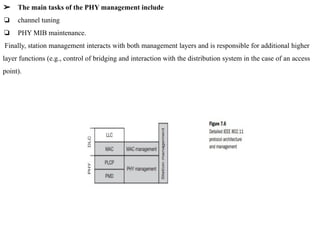
➢ The physical layer is subdivided into the
❏ physical layer convergence protocol (PLCP)
❏ physical medium dependent sublayer PMD (see Figure 7.6).
➢ The basic tasks of the MAC layer comprise
❏ medium access
❏ fragmentation of user data
❏ encryption.
19.
➢ The PLCPsublayer provides
❏ a carrier sense signal, called clear channel assessment (CCA)
❏ a common PHY service access point (SAP) independent of the transmission technology.
➢ The PMD sublayer handles
❏ modulation
❏ encoding/decoding of signals.
The PHY layer (comprising PMD and PLCP) and the MAC layer.
➢ The MAC management
❏ supports the association and reassociation of a station to an access point
❏ roaming between different access points.
❏ It also controls authentication mechanisms
❏ encryption
❏ synchronization of a station with regard to an access point,
❏ power management to save battery power.
❏ maintains the MAC management information base (MIB).
20.
➢ The maintasks of the PHY management include
❏ channel tuning
❏ PHY MIB maintenance.
Finally, station management interacts with both management layers and is responsible for additional higher
layer functions (e.g., control of bridging and interaction with the distribution system in the case of an access
point).
21.
Physical layer
❏ IEEE802.11 supports three different physical layers:
➢ one layer based on infra red
➢ two layers based on radio transmission (Frequency hopping spread spectrum,Direct sequence
spread spectrum).
❏ All PHY variants include the provision of the clear channel assessment signal (CCA).
❏ This is needed for the MAC mechanisms controlling medium access and indicates if the medium
is currently idle.
❏ The PHY layer offers a service access point (SAP) with 1 or 2 Mbit/s transfer rate to the MAC
layer (basic version of the standard).
22.
Frequency hopping spreadspectrum
➢ Frequency hopping spread spectrum (FHSS) is a spread spectrum technique which allows for the
coexistence of multiple networks in the same area by separating different networks using different
hopping sequences.
➢ The standard specifies Gaussian shaped FSK (frequency shift keying), GFSK, as modulation for
the FHSS PHY.
➢ For 1 Mbit/s a 2 level GFSK is used (i.e., 1 bit is mapped to one frequency), a 4 level GFSK for 2
Mbit/s (i.e., 2 bits are mapped to one frequency).
➢ While sending and receiving at 1 Mbit/s is mandatory for all devices, operation at 2 Mbit/s is
optional.
➢ This facilitated the production of low-cost devices for the lower rate only and more powerful
devices for both transmission rates in the early days of 802.11.
23.
FRAME STRUCTURE ofFHSS
➢ Figure 7.7 shows a frame of the physical layer used with FHSS.
➢ The frame consists of two basic parts
❏ the PLCP part (preamble and header)
❏ the payload part.
While the PLCP part is always transmitted at 1 Mbit/s, payload, i.e. MAC data, can use 1 or 2 Mbit/s.
24.
The fields ofthe frame are:
● Synchronization: The PLCP preamble starts with 80 bit synchronization, which is a 010101... bit
pattern. This pattern is used for synchronization of potential receivers and signal detection by the CCA.
● Start frame delimiter (SFD): The following 16 bits indicate the start of the frame and provide
frame synchronization. The SFD pattern is 0000110010111101.
● PLCP_PDU length word (PLW): This first field of the PLCP header indicates the length of the
payload in bytes including the 32 bit CRC at the end of the payload. PLW can range between 0 and
4,095.
● PLCP signalling field (PSF): This 4 bit field indicates the data rate of the payload following. All
bits set to zero (0000) indicates the lowest data rate of 1 Mbit/s. The granularity is 500 kbit/s, thus 2
Mbit/s is indicated by 0010 and the maximum is 8.5 Mbit/s (1111). This system obviously does not
accommodate today’s higher data rates.
● Header error check (HEC): Finally, the PLCP header is protected by a 16 bit checksum with the
standard ITU-T generator polynomial
25.
Direct sequence spreadspectrum
➢ Direct sequence spread spectrum (DSSS) is the alternative spread spectrum method separating by code
and not by frequency.
➢ In the case of IEEE 802.11 DSSS, spreading is achieved using the 11-chip Barker sequence (+1, –1, +1,
+1, –1, +1, +1, +1, –1, –1, –1).
➢ The key characteristics of this method are its robustness against interference and its insensitivity to
multipath propagation (time delay spread).
➢ However, the implementation is more complex compared to FHSS.
➢ IEEE 802.11 DSSS PHY also uses the 2.4 GHz ISM band and offers both 1 and 2 Mbit/s data rates.
➢ The system uses differential binary phase shift keying (DBPSK) for 1 Mbit/s transmission and
differential quadrature phase shift keying (DQPSK) for 2 Mbit/s as modulation schemes.
➢ Again, the maximum transmit power is 1 W in the US, 100 mW EIRP in Europe and 10 mW/MHz in
Japan.
➢ The symbol rate is 1 MHz, resulting in a chipping rate of 11 MHz. All bits transmitted by the DSSS
PHY are scrambled with the polynomial s(z) = z7 + z4 + 1 for DC blocking and whitening of the
spectrum.
26.
Figure 7.8 showsa frame of the physical layer using DSSS.
The frame consists of two basic parts, the PLCP part (preamble and header) and the payload part.
While the PLCP part is always transmitted at 1 Mbit/s, payload, i.e., MAC data, can use 1 or 2 Mbit/s.
The fields of the frame have the following functions:
● Synchronization: The first 128 bits are not only used for synchronization, but also gain setting,
energy detection (for the CCA), and frequency offset compensation. The synchronization field only
consists of scrambled 1 bits.
● Start frame delimiter (SFD): This 16 bit field is used for synchronization at the beginning of a frame
and consists of the pattern 1111001110100000.
● Signal: Originally, only two values have been defined for this field to indicate the data rate of the
payload. The value 0x0A indicates 1 Mbit/s (and thus DBPSK), 0x14 indicates 2 Mbit/s (and thus
DQPSK). Other values have been reserved for future use, i.e., higher bit rates.
● Service: This field is reserved for future use; however, 0x00 indicates an IEEE 802.11 compliant
frame.
● Length: 16 bits are used in this case for length indication of the payload in microseconds.
● Header error check (HEC): Signal, service, and length fields are protected by this checksum using
the ITU-T CRC-16 standard polynomial.
27.
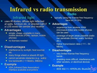
Infra red
➢ ThePHY layer, which is based on infra red (IR) transmission, uses near visible light at 850–950
nm.
➢ Infra red light is not regulated apart from safety restrictions (using lasers instead of LEDs).
➢ The standard does not require a line-of-sight between sender and receiver, but should also work
with diffuse light. This allows for point-to-multipoint communication.
➢ The maximum range is about 10 m if no sunlight or heat sources interfere with the
transmission.
➢ Typically, such a network will only work in buildings, e.g., classrooms, meeting rooms etc.
➢ Frequency reuse is very simple – a wall is more than enough to shield one IR based IEEE
802.11 network from another.
28.
Medium access controllayer (MAC)
➢ The MAC layer has to fulfill several tasks
❏ to control medium access
❏ offer support for roaming
❏ authentication
❏ power conservation.
➢ The basic services provided by the MAC layer are
❏ the mandatory asynchronous data service
❏ an optional time-bounded service.
The MAC mechanisms are also called distributed foundation wireless medium access control
(DFWMAC).
29.
MAC frames
The Figureshows the basic structure of an IEEE 802.11 MAC data frame together with the content of the frame control
field. The fields in the figure refer to the following:
● Frame control: The first 2 bytes serve several purposes. They contain several sub-fields as
explained after the MAC frame.
● Duration/ID: If the field value is less than 32,768, the duration field contains the value
indicating the period of time in which the medium is occupied (in µs). This field is used for
setting the NAV for the virtual reservation mechanism using RTS/CTS and during fragmentation.
Certain values above 32,768 are reserved for identifiers.
● Address 1 to 4: The four address fields contain standard IEEE 802 MAC addresses (48 bit
each), as they are known from other 802.x LANs. The meaning of each address depends on the
DS bits in the frame control field
● Sequence control: Due to the acknowledgement mechanism frames may be duplicated.
Therefore a sequence number is used to filter duplicates.
● Data: The MAC frame may contain arbitrary data (max. 2,312 byte), which is transferred
transparently from a sender to the receiver(s).
● Checksum (CRC): Finally, a 32 bit checksum is used to protect the frame as it is common
practice in all 802.x networks.
30.
The frame controlfield shown in Figure 7.16 contains the following fields:
● Protocol version: This 2 bit field indicates the current protocol version and is fixed to 0 by now.
If major revisions to the standard make it incompatible with the current version, this value will be
increased.
● Type: The type field determines the function of a frame: management (=00), control (=01), or data
(=10). The value 11 is reserved. Each type has several subtypes as indicated in the following field.
● Subtype: Example subtypes for management frames are: 0000 for association request, 1000 for
beacon. RTS is a control frame with subtype 1011, CTS is coded as 1100. User data is transmitted as
data frame with subtype 0000.
To DS/From DS: Used to control meaning of the address field in the MAC frame
● More fragments: This field is set to 1 in all data or management frames that have another
fragment of the current MSDU to follow.
● Retry: If the current frame is a retransmission of an earlier frame, this bit is set to 1. With the help
of this bit it may be simpler for receivers to eliminate duplicate frames.
● Power management: This field indicates the mode of a station after successful transmission of a
frame. Set to 1 the field indicates that the station goes into power-save mode. If the field is set to 0,
the station stays active.
● More data: In general, this field is used to indicate a receiver that a sender has more data to send
than the current frame. This can be used by an access point to indicate to a station in power-save
mode that more packets are buffered. Or it can be used by a station to indicate to an access point
after being polled that more polling is necessary as the station has more data ready to transmit.
● Wired equivalent privacy (WEP): This field indicates that the standard security mechanism of
802.11 is applied. However, due to many weaknesses found in the WEP algorithm higher layer
security should be used to secure an 802.11 network (Borisov, 2001).
● Order: If this bit is set to 1 the received frames must be processed in strict order.
31.
MAC management
MAC managementplays a central role in an IEEE 802.11 station as it more or less controls all
functions related to system integration, i.e., integration of a wireless station into a BSS, formation of an
ESS, synchronization of stations etc.
The following functional groups have been identified and will be discussed in more detail in the
following sections:
● Synchronization: Functions to support finding a wireless LAN, synchronization of internal clocks,
generation of beacon signals.
● Power management: Functions to control transmitter activity for power conservation, e.g., periodic
sleep, buffering, without missing a frame.
● Roaming: Functions for joining a network (association), changing access points, scanning for access
points.
● Management information base (MIB): All parameters representing the current state of a wireless
station and an access point are stored within a MIB for internal and external access. A MIB can be
accessed via standardized protocols such as the simple network management protocol (SNMP).
36.
Bluetooth
● Bluetooth technologyis local area networks with a very limited coverage and without the need for
an infrastructure.
● This is a different type of network is needed to connect different small devices in close proximity
(about 10 m) without expensive wiring or the need for a wireless infrastructure .
● Bluetooth was initiated by Swedish IT-company Ericsson.
● In spring 1998 five companies (Ericsson, Intel, IBM, Nokia, Toshiba) founded the Bluetooth
consortium with the goal of developing a single-chip, low-cost, radio-based wireless network
technology.
● Many other companies and research institutions joined the special interest group around
Bluetooth, whose goal was the development of mobile phones, laptops, notebooks, headsets etc.
including Bluetooth technology, by the end of 1999.
● In 2001, the first products hit the mass market, and many mobile phones, laptops, PDAs, video
cameras etc. are equipped with Bluetooth technology today.
37.
User scenarios
Many differentuser scenarios can be imagined for wireless piconets or WPANs:
● Connection of peripheral devices: Today, most devices are connected to a desktop computer via wires (e.g.,
keyboard, mouse, joystick, headset, speakers). This type of connection has several disadvantages: each device has its
own type of cable, different plugs are needed, wires block office space. In a wireless network, no wires are needed for
data transmission. However, batteries now have to replace the power supply, as the wires not only transfer data but
also supply the peripheral devices with power.
● Support of ad-hoc networking: Imagine several people coming together, discussing issues, exchanging data
(schedules, sales figures etc.). For instance, students might join a lecture, with the teacher distributing data to their
personal digital assistants (PDAs). Wireless networks can support this type of interaction; small devices might not
have WLAN adapters following the IEEE 802.11 standard, but cheaper Bluetooth chips built in.
Bridging of networks: Using wireless piconets, a mobile phone can be connected to a PDA or laptop in a simple
way. Mobile phones will not have full WLAN adapters built in, but could have a Bluetooth chip. The mobile
phone can then act as a bridge between the local piconet and, e.g., the global GSM network (see Figure 7.40). For
instance, on arrival at an airport, a person’s mobile phone could receive e-mail via GSM and forward it to the
laptop which is still in a suitcase. Via a piconet, a fileserver could update local information stored on a laptop or
PDA while the person is walking into the office.
38.
Features
➢ Bluetooth operatesin the 2.4 GHz ISM band.
➢ Bluetooth operates on 79 channels in the 2.4 GHz band with 1 MHz carrier spacing.
➢ Bluetooth uses Gaussian-shaped Frequency Shift Keying (GFSK) modulation with a nominal
modulation index of K = 0.3
➢ Each device performs frequency hopping with 1,600 hops/s in a pseudo random fashion.
➢ Bluetooth applies FHSS for interference mitigation.
39.
Architecture
➢ A veryimportant term in the context of Bluetooth is a piconet.
➢ A piconet is a collection of Bluetooth devices which are synchronized to the same hopping
sequence.
➢ Figure 7.41 shows a collection of devices with different roles.
➢
One device in the piconet can act as master (M), all other devices connected to the master must
act as slaves (S).
40.
➢ The masterdetermines the hopping pattern in the piconet and the slaves have to synchronize to this
pattern.
➢ Each piconet has a unique hopping pattern.
➢ If a device wants to participate it has to synchronize to that pattern.
➢ Two additional types of devices are shown:
➢ parked devices (P) can not actively participate in the piconet (i.e., they do not have a connection),
but are known and can be reactivated within some milliseconds
➢ Devices in stand-by (SB) do not participate in the piconet.
➢ Each piconet has exactly one master and up to seven simultaneous slaves.
➢ More than 200 devices can be parked.
➢ The reason for the upper limit of eight active devices, is the 3-bit address used in Bluetooth.
➢ If a parked device wants to communicate and there are already seven active slaves, one slave has to
switch to park mode to allow the parked device to switch to active mode.
➢ As all active devices have to use the same hopping sequence they must be synchronized.
➢ The first step involves a master sending its clock and device ID.
41.
➢ All Bluetoothdevices have the same networking capabilities, i.e., they can be master or slave.
There is no distinction between terminals and base stations, any two or more devices can form a
piconet.
➢ The unit establishing the piconet automatically becomes the master, all other devices will be
slaves.
➢ The hopping pattern is determined by the device ID, a 48-bit worldwide unique identifier.
➢ The phase in the hopping pattern is determined by the master’s clock.
➢ After adjusting the internal clock according to the master a device may participate in the piconet.
➢ All active devices are assigned a 3-bit active member address (AMA).
➢ All parked devices use an 8-bit parked member address (PMA). Devices in stand-by do not need
an address.
42.
Scatternet
➢ All userswithin one piconet have the same hopping sequence and share the same 1 MHz channel.
➢ As more users join the piconet, the throughput per user drops quickly (a single piconet offers less
than 1 Mbit/s gross data rate).
➢ This led to the idea of forming groups of piconets called scatternet .
➢ Only those units that really must exchange data share the same piconet, so that many piconets with
overlapping coverage can exist simultaneously.
➢ If a device wants to participate in more than one piconet, it has to synchronize to the hopping
sequence of the piconet it wants to take part in.
➢ If a device acts as slave in one piconet, it simply starts to synchronize with the hopping sequence of
the piconet it wants to join.
➢ After synchronization, it acts as a slave in this piconet and no longer participates in its former
piconet. To enable synchronization, a slave has to know the identity of the master that determines
the hopping sequence of a piconet.
➢ Before leaving one piconet, a slave informs the current master that it will be unavailable for a
certain amount of time.
➢ The remaining devices in the piconet continue to communicate as usual
43.
➢ A mastercan also leave its piconet and act as a slave in another piconet.
➢ It is clearly not possible for a master of one piconet to act as the master of another piconet as
this would lead to identical behavior.
➢ As soon as a master leaves a piconet, all traffic within this piconet is suspended until the master
returns.
➢ Communication between different piconets takes place by devices jumping back and forth
between theses nets.
➢ However, scatternets are not yet supported by all devices.
44.
Protocol stack
➢ TheBluetooth protocol stack can be divided into a core specification which describes the protocols
from physical layer to the data link control together with management functions, and profile
specifications .
➢ The core protocols of Bluetooth comprise the following elements:
● Radio: Specification of the air interface, i.e., frequencies, modulation, and transmit power .
● Baseband: Description of basic connection establishment, packet formats, timing, and basic QoS
parameters
● Link manager protocol: Link set-up and management between devices including security
functions and parameter negotiation.
● Logical link control and adaptation protocol (L2CAP): Adaptation of higher layers to the
baseband (connectionless and connection-oriented services, see section 7.5.6).
● Service discovery protocol: Device discovery in close proximity plus querying of service
characteristics