Materials and Methods for Repair and Rehabilitation
1. EM 1110-2-2002
30 Jun 95
Chapter 6
Materials and Methods for Repair and
Rehabilitation
6-1. Introduction
This chapter contains descriptions of various materials and
methods that are available for repair or rehabilitation of
concrete structures. Each of the entries in this chapter
will include description, applications and limitations, and
procedure. Although the repair procedures given in this
chapter are current practice, they may not be used directly
in project specifications because each repair project may
require unique remedial action. Emmons (1993) provides
a discussion of materials and methods for concrete repair
with extensive, detailed illustrations.
6-2. Additional Reinforcement
a. Description. Additional reinforcement, as the
name implies, is the provision of additional reinforcing
steel, either conventional reinforcement or prestressing
steel, to repair a cracked concrete section. In either case,
the steel that is added is to carry the tensile forces that
have caused cracking in the concrete.
b. Applications and limitations. Cracked reinforced
concrete bridge girders have been successfully repaired by
use of additional conventional reinforcement (Stratton,
Alexander, and Nolting 1982). Posttensioning is often the
desirable solution when a major portion of a member
must be strengthened or when the cracks that have formed
must be closed. For the posttensioning method, some
form of abutment is needed for anchorage, such as a
strongback bolted to the face of the concrete, or the ten-
dons can be passed through and anchored in connecting
framing.
c. Procedure.
(1) Conventional reinforcement.
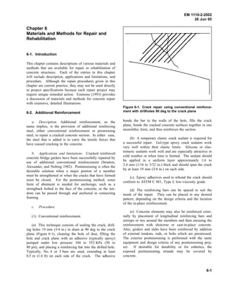
(a) This technique consists of sealing the crack, drill-
ing holes 19 mm (3/4 in.) in diam at 90 deg to the crack
plane (Figure 6-1), cleaning the hole of dust, filling the
hole and crack plane with an adhesive (typically epoxy)
pumped under low pressure 344 to 552 KPa (50 to
80 psi), and placing a reinforcing bar into the drilled hole.
Typically, No. 4 or 5 bars are used, extending at least
0.5 m (1.6 ft) on each side of the crack. The adhesive
Figure 6-1. Crack repair using conventional reinforce-
ment with drillholes 90 deg to the crack plane
bonds the bar to the walls of the hole, fills the crack
plane, bonds the cracked concrete surfaces together in one
monolithic form, and thus reinforces the section.
(b) A temporary elastic crack sealant is required for
a successful repair. Gel-type epoxy crack sealants work
very well within their elastic limits. Silicone or elas-
tomeric sealants work well and are especially attractive in
cold weather or when time is limited. The sealant should
be applied in a uniform layer approximately 1.6 to
2.4 mm (1/16 to 3/32 in.) thick and should span the crack
by at least 19 mm (3/4 in.) on each side.
(c) Epoxy adhesives used to rebond the crack should
conform to ASTM C 881, Type I, low-viscosity grade.
(d) The reinforcing bars can be spaced to suit the
needs of the repair. They can be placed in any desired
pattern, depending on the design criteria and the location
of the in-place reinforcement.
(e) Concrete elements may also be reinforced exter-
nally by placement of longitudinal reinforcing bars and
stirrups or ties around the members and then encasing the
reinforcement with shotcrete or cast-in-place concrete.
Also, girders and slabs have been reinforced by addition
of external tendons, rods, or bolts which are prestressed.
The exterior posttensioning is performed with the same
equipment and design criteria of any posttensioning proj-
ect. If desirable for durability or for esthetics, the
exposed posttensioning strands may be covered by
concrete.
6-1
2. EM 1110-2-2002
30 Jun 95
(2) Prestressing steel. This technique uses prestress-
ing strands or bars to apply a compressive force (Fig-
ure 6-2). Adequate anchorage must be provided for the
prestressing steel, and care is needed so that the problem
will not merely migrate to another part of the structure.
The effects of the tensioning force (including eccentricity)
on the stress within the structure should be carefully ana-
lyzed. For indeterminate structures posttensioned accord-
ing to this procedure, the effects of secondary moments
and induced reactions should be considered.
Figure 6-2. Crack repair with use of external prestress-
ing strands or bars to apply a compressive force
(3) Steel plates. Cracks in slabs on grade have been
repaired by making saw cuts 50 to 75 mm (2 to 3 in.)
deep across the crack and extending 150 to 300 mm (6 to
12 in.) on either side of the crack, filling the saw cuts and
the crack with epoxy, and forcing a steel plate of appro-
priate size into each saw cut.
6-3. Autogenous Healing
a. Description. Autogenous healing is a natural pro-
cess of crack repair that can occur in the presence of
moisture and the absence of tensile stress (Lauer 1956).
b. Applications and limitations. Autogenous healing
has practical application for closing dormant cracks in a
moist environment. Healing will not occur if the crack is
active and is subjected to movement during the healing
period. Healing will also not occur if there is a positive
flow of water through the crack which dissolves and
washes away the lime deposit. A partial exception is a
situation in which the flow of water is so slow that com-
plete evaporation occurs at the exposed face causing rede-
position of the dissolved salts.
c. Mechanism. Healing occurs through the car-
bonation of calcium hydroxide in the cement paste by car-
bon dioxide, which is present in the surrounding air and
water. Calcium carbonate and calcium hydroxide crystals
precipitate, accumulate, and grow within the cracks. The
crystals interlace and twine, producing a mechanical bond-
ing effect, which is supplemented by chemical bonding
between adjacent crystals and between the crystals and the
surfaces of the paste and the aggregate. As a result, some
of the tensile strength of the concrete is restored across
the cracked section, and the crack may become sealed.
Saturation of the crack and the adjacent concrete with
water during the healing process is essential for develop-
ing any substantial strength. Continuous saturation
accelerates the healing. A single cycle of drying and
reimmersion will produce a drastic reduction in the
amount of healing.
6-4. Conventional Concrete Placement
a. Description. This method consists of replacing
defective concrete with a new conventional concrete mix-
ture of suitable proportions that will become an integral
part of the base concrete. The concrete mixture propor-
tions must provide for good workability, strength, and
durability. The repair concrete should have a low w/c and
a high percentage of coarse aggregate to minimize shrink-
age cracking.
b. Applications and limitations. If the defects in
the structure go entirely through a wall or if the defects
go beyond the reinforcement and if the defective area is
large, then concrete replacement is the desired method.
Replacement is sometimes necessary to repair large areas
of honeycomb in new construction. Conventional con-
crete should not be used for replacement in areas where
an aggressive factor which has caused the deterioration of
the concrete being replaced still exists. For example, if
the deterioration noted has been caused by acid attack,
aggressive-water attack, or even abrasion-erosion, it is
doubtful that repair by conventional-concrete placement
will be successful unless the cause of deterioration is
removed. Concrete replacement methods for repairing
lock walls and stilling basins are given in Sections 8-1
and 8-3, respectively, and repair by placing a thin
concrete overlay is discussed in Section 6-17.
6-2
3. EM 1110-2-2002
30 Jun 95
c. Procedure.
(1) Concrete removal is always required for this type
of repair. Removal of affected areas should continue until
there is no question that sound concrete has been reached.
Additional chipping may be necessary to attain a satisfac-
tory depth (normally 150 mm (6 in.) or more) and to
shape the cavity properly. Final chipping should be done
with a light hammer to remove any unsound concrete that
remains. In a vertical surface (Figure 6-3), the cavity
should have the following:
(a) A minimum of spalling or featheredging at the
periphery of the repair area.
(b) Vertical sides and horizontal top at the surface of
the member (the top line of the cavity may be stepped).
(c) Inside faces generally normal to the formed sur-
face, except that the top should slope up toward the front
at about a 1:3 slope.
(d) Keying as necessary to lock the repair into the
structure.
(e) Sufficient depth to reach at least 6 mm (1/4 in.)
plus the dimension of the maximum size aggregate behind
any reinforcement.
(f) All interior corners rounded with a radius of
about 25 mm (1 in.).
(2) Surfaces must be thoroughly cleaned by sand-
blasting (wet or dry), shotblasting, or another equally
satisfactory method, followed by final cleaning with com-
pressed air or water. Sandblasting effects should be con-
fined to the surface that is to receive the new concrete.
Dowels and reinforcement are often installed to make the
patch self-sustaining and to anchor it to the underlying
concrete, thus providing an additional safety factor.
(3) Forming will usually be required for massive
repairs in vertical surfaces. The front form and the back
form, where one is required, should be substantially con-
structed and mortartight. The back form may be assem-
bled in one piece, but the front panel should be
constructed as placing progresses so that the concrete can
be conveniently placed in lifts. The contact surface
should be dry at the time of patching. Small, thin repairs
(less than 50 mm (2 in.) thick) should receive a bonding
coat while thicker placements usually do not require a
bonding coat (see paragraph 5-3a(2)(f)). The surface is
first carefully coated with a thin layer of mortar, not
exceeding 3 mm (1/8 in.) in thickness, containing sand
passing the No. 16 sieve, and having the same w/c as the
concrete to be used in the replacement. Hand-rubbing the
mortar into the surface is effective. Epoxy resin
Figure 6-3. Detail of form for concrete replacement in walls after removal of all unsound concrete
6-3
4. EM 1110-2-2002
30 Jun 95
meeting ASTM C 881, Type II or Type V may also be
used. ACI 503.2 provides a standard specification for
bonding plastic concrete to hardened concrete with epoxy
adhesives.
(4) Concrete used for repair should conform to
EM 1110-2-2000. To minimize strains caused by tem-
perature, moisture change, shrinkage, etc., concrete for the
repair should generally be similar to the old concrete in
maximum size of aggregate and w/c. Each lift should be
thoroughly vibrated. Internal vibration should be used
except where accessibility and size of placement will not
allow it. If internal vibration can not be used, external
vibration may be used. If external vibration must be
used, placement through a chimney, followed by a pres-
sure cap (Figure 6-3) should be required. If good internal
vibration can be accomplished, the pressure cap may not
be needed. The slump should be as low as practical, and
a chimney and pressure cap should be used. A tighter
patch results if the concrete is placed through a chimney
at the top of the front form.
(5) When external vibration is necessary, immediately
after the cavity has been filled, a pressure cap should be
placed inside the chimney (Figure 6-3). Pressure should
be applied while the form is vibrated. This operation
should be repeated at 30-min intervals until the concrete
hardens and no longer responds to vibration. The projec-
tion left by the chimney should normally be removed the
second day. Proper curing is essential.
(6) The form and pump technique is often used to
place conventional concrete (or other materials) in vertical
or over head applications. The proper size variable output
concrete pump is used to pump concrete into a cavity
confined by formwork. Care must be taken to trim the
original concrete surfaces that may entrap air, or these
areas may be vented. Forming must be nearly watertight
and well braced so that pressure from the pumps can help
achieve bonding of the new concrete to the old.
(7) Curing of concrete repairs is very important,
especially if relatively thin repairs are made in hot
weather. Shrinkage cracks can develop quickly under
such conditions. Moist curing conforming to the guide-
lines in EM 1110-2-2000 is the preferred curing method.
6-5. Crack Arrest Techniques
a. Description. Crack arrest techniques are those
procedures that may be used during the construction of a
massive concrete structure to stop crack propagation into
subsequent concrete lifts.
b. Applications and limitations. These techniques
should be used only for cracking caused by restrained
volume change of the concrete. They should not be used
for cracking caused by excessive loading.
c. Procedure. During construction of massive con-
crete structures, contraction cracks may develop as the
concreting progresses. Such cracks may be arrested by
use of the following techniques.
(1) The simplest technique is to place a grid of
reinforcing steel over the cracked area. The reinforcing
steel should be surrounded by conventional concrete
rather than the mass concrete being used in the structure.
(2) A somewhat more complex procedure is to use a
piece of semicircular pipe as shown in Figure 6-4. The
installation procedure is as follows: First, the semicir-
cular pipe is made by splitting a 200-mm (8-in.)-diam
piece of 16-gauge pipe and bending it to a semicircular
shape with about a 76-mm- (3-in.-) flange on each side.
Then, the area surrounding the crack should be well
cleaned and the pipe should be centered on the crack.
Once in place, the sections of the pipe should be welded
together. Holes should be cut into the pipe to receive
grout pipes. Finally, the pipe section should be covered
with concrete placed concentrically by hand methods.
The grout pipes may be used for grouting at a later date
to attempt to restore structural integrity of the cracked
section.
(3) A piece of bond-breaking membrane placed on a
construction joint over the crack has been used with vary-
ing degrees of success.
Figure 6-4. The use of a semicircular pipe in the crack
arrest method of concrete repair
6-4
5. EM 1110-2-2002
30 Jun 95
6-6. Drilling and Plugging
a. Description. Drilling and plugging a crack con-
sists of drilling down the length of the crack and grouting
it to form a key (Figure 6-5).
Figure 6-5. Repair of crack by drilling and plugging
b. Applications and limitations. This technique is
applicable only where cracks run in reasonably straight
lines and are accessible at one end. This method is most
often used to repair vertical cracks in walls.
(1) Procedure. A hole (typically 50 to 75 mm (2 to
3 in.) in diam) should be drilled, centered on, and fol-
lowing the crack. The hole must be large enough to
intersect the crack along its full length and provide
enough repair material to structurally take the loads
exerted on the key. The drilled hole should then be
cleaned and filled with grout. The grout key prevents
transverse movement of the sections of concrete adjacent
to the crack. The key will also reduce heavy leakage
through the crack and loss of soil from behind a leaking
wall.
(2) If watertightness is essential and structural load
transfer is not, the drilled hole should be filled with a
resilient material of low modulus such as asphalt or poly-
urethane foam in lieu of portland-cement grout. If the
keying effect is essential, the resilient material can be
placed in a second hole, the first being grouted.
6-7. Drypacking
a. Description. Drypacking is a process of ram-
ming or tamping into a confined area a low water-content
mortar. Because of the low w/c material, there is little
shrinkage, and the patch remains tight and is of good qua-
lity with respect to durability, strength, and watertightness.
This technique has an advantage in that no special equip-
ment is required. However, the method does require that
the craftsman making the repair be skilled in this particu-
lar type of work.
b. Applications and limitations. Drypacking can be
used for patching rock pockets, form tie holes, and small
holes with a relatively high ratio of depth to area. It
should not be used for patching shallow depressions
where lateral restraint cannot be obtained, for patching
areas requiring filling in back of exposed reinforcement,
nor for patching holes extending entirely through concrete
sections. Drypacking can also be used for filling narrow
slots cut for the repair of dormant cracks. The use of
drypack is not recommended for filling or repairing active
cracks.
c. Procedure.
(1) The area to be repaired should be undercut
slightly so that the base width is slightly greater than the
surface width. For repairing dormant cracks, the portion
adjacent to the surface should be widened to a slot about
25 mm (1 in.) wide and 25 mm (1 in.) deep. This is most
conveniently done with a power-driven sawtooth bit. The
slot should also be undercut slightly. After the area or
slot is thoroughly cleaned and dried, a bond coat should
be applied. Placing of the drypack mortar should begin
immediately. The mortar usually consists of one part
cement, two and one-half to three parts sand passing a
No. 16 sieve, and only enough water so that the mortar
will stick together when molded into a ball by slight
pressure of the hands and will not exude water but will
leave the hands dry. Latex-modified mortar is being
increasingly used in lieu of straight portland-cement
mortar. Preshrunk mortar may be used to repair areas too
small for the tamping procedure. Preshrunk mortar is a
low water-content mortar that has been mixed and
allowed to stand idle 30 to 90 min, depending on the
temperature, prior to use. Remixing is required after the
idle period.
(2) Drypack mortar should be placed in layers hav-
ing a compacted thickness of about 10 mm (3/8 in.).
6-5
6. EM 1110-2-2002
30 Jun 95
Each layer should be compacted over its entire surface by
use of a hardwood stick. For small areas, the end of the
stick is placed against the mortar and tamping is begun at
the middle of the area and progresses toward the edges to
produce a wedging effect. For larger areas, a T-shaped
rammer may be used; the flat head of the T is placed
against the mortar and hammered on the stem. It is usu-
ally necessary to scratch the surface of the compacted
layers to provide bond for the next layer. Successive
layers of drypack are placed without interval, unless the
material becomes spongy, in which case there should be a
short wait until the surface stiffens. Areas should be
filled flush and finished by striking a flat-sided board or
the flat of the hardwood stick against the surface. Steel
trowelling is not suitable. After being finished, the
repaired area should be cured. If the patch must match
the color of the surrounding concrete, a blend of portland
cement and white cement may be used. Normally, about
one-third white cement is adequate, but the precise pro-
portions can only be determined by trial.
6-8. Fiber-Reinforced Concrete
a. Description. Fiber-reinforced concrete is com-
posed of conventional portland-cement concrete contain-
ing discontinuous discrete fibers. The fibers are added to
the concrete in the mixer. Fibers are made from steel,
plastic, glass, and other natural materials. A convenient
numerical parameter describing a fiber is its aspect ratio,
defined as the fiber length divided by an equivalent fiber
diameter. Typical aspect ratios range from about 30 to
150 for lengths of 6.4 to 76 mm (0.25 to 3 in.).
b. Applications and limitations. Fiber-reinforced
concrete has been used extensively for pavement repair.
Fiber-reinforced concrete has been used to repair erosion
of hydraulic structures caused by cavitation or high veloc-
ity flow and impact of large debris (ACI 210R). How-
ever, laboratory tests and field experience show that the
abrasion-erosion resistance of fiber-reinforced concrete is
significantly less than that of conventional concrete with
the same w/c and aggregate type (Liu 1980, Liu and
McDonald 1981). The slump of a concrete mixture is
significantly reduced by the addition of fibers. Use of the
inverted slump cone test for workability is recommended.
Reliance on slump tests often results in the use of exces-
sive water in an attempt to maintain a slump, without
improving workability. A fiber mixture will generally
require more vibration to consolidate the concrete.
c. Procedure. Preparation of the area to be repaired,
mixing, transporting, placing, and finishing
fiber-reinforced concrete follows the procedures for and
generally uses the same equipment as plain concrete
(ACI 544.3R). Pumping of steel fiber-reinforced concrete
with up to 1.5 percent fibers by volume has been done
successfully. Three-pronged garden forks are preferable
to shovels for handling the fiber-reinforced concrete.
Mixture design and especially the amount of fibers used
are critical so that design parameters for strength and
durability are met and the mixture will still be workable.
About 2 percent by volume is considered a practical upper
limit for field placement with the necessary workability.
Steel fiber-reinforced shotcrete, with up to 2.0 percent
fibers by volume, generally mixed with the dry-mixture
process has been successfully used to repair concrete.
Polypropylene fibers have been added to acrylic polymer
modified concrete for repair of a lockwall
(Dahlquist 1987).
6-9. Flexible Sealing
a. Description. Flexible sealing involves routing
and cleaning the crack and filling it with a suitable field-
molded flexible sealant. This technique differs from
routing and sealing in that, in this case, an actual joint is
constructed, rather than a crack simply being filled.
b. Applications and limitations. Flexible sealing
may be used to repair major, active cracks. It has been
successfully used in situations in which there is a limited
water head on the crack. This repair technique does not
increase the structural capacity of the cracked section.
Another process used to form a flexible joint from an
active or inactive water-filled crack is described in Sec-
tion 6-11. This process may be used in lieu of or in
addition to flexible sealing. Chemical grouting is a more
complicated and expensive procedure, but it can be used
in conditions of flowing water.
c. Procedure. Active cracks can be routed out;
cleaned by sandblast or air-water jet, or both; and filled
with a suitable field-molded flexible sealant
(ACI 224.1R). As nearly as is practical, the sealant reser-
voir (slot) formed by routing should comply with the
requirements for width and shape factor of a joint having
equivalent movement. The selection of a suitable sealant
and installation method should follow that for equivalent
joints (ACI 504R).
(1) A bond breaker should be provided at the bottom
of the slot to allow the sealant to change shape without a
concentration of stress on the bottom (Figure 6-6). The
bond breaker may be a polyethylene strip, pressure sensi-
tive tape, or other material which will not bond to the
sealant before or during cure.
6-6
7. EM 1110-2-2002
30 Jun 95
Figure 6-6. Effect of bond breaker involving a field-molded flexible sealant
(2) If a bond breaker is used over the crack, a flexi-
ble joint sealant may be trowelled over the bond breaker
to provide an adequate bonding area. This is a very eco-
nomical procedure and may be used on the interior of a
tank, on roofs, or other areas not subject to traffic or
mechanical abuse.
(3) Narrow cracks subject to movement, where
esthetics are not important, may be sealed with a flexible
surface seal (Figure 6-7).
Figure 6-7. Repair of a narrow crack with flexible sur-
face seal
(4) When repairing cracks in canal and reservoir
linings or low-head hydraulic structures where water
movement or pressure exists, a retaining cap must be used
to confine the sealant. A simple retainer can be made by
positioning a metal strip across the crack and fastening it
to expandable anchors or grouted bolts installed in the
concrete along one side of the crack. To maintain
hydraulic efficiency in some structures, it may be
necessary to cut the concrete surface adjacent to the crack
and to place the retaining cap flush with the original flow
lines (Figure 6-8).
Figure 6-8. Repair of crack by use of a retainer plate to
hold mastic in place against external pressure
6-10. Gravity Soak
a. Description. High molecular weight methacry-
late (HMWM) is poured or sprayed onto any horizontal
concrete surface and spread by broom or squeegee. The
6-7
8. EM 1110-2-2002
30 Jun 95
material penetrates very small cracks by gravity and capil-
lary action, polymerizing to form a “plug” which closes
off access to the reinforcing steel (Montani 1993).
b. Applications and limitations. Repairing cracks
with the gravity soak method and HMWM has become a
proven and cost-effective method. Gravity soak can be an
effective repair method for horizontal concrete surfaces
that contain excessive, closely spaced shrinkage cracking.
This would include bridge decks, parking decks, industrial
floors, pavements etc. HMWM’s should not be confused
with methyl methacrylates (MMA’s). While MMA’s are
very volatile and have a low flash point, HMWM’s have a
high flashpoint, and are quite safe to use.
c. Procedure. New concrete must have cured for at
least 1 week and must be air-dry. Air-drying is necessary
after a rainfall. New concrete surfaces may simply be
swept clean before application, but older surfaces will
require cleaning of all oil, grease, tar, or other con-
taminants and sand blasting. The monomer is mixed with
the catalyst and quickly poured onto the concrete surface.
Two-component systems should be specified. Three-
component systems are not recommended because impro-
per mixing sequences can be dangerous. The material is
spread by a broom or squeegee. Larger individual cracks
can sometimes be treated by use of a squeegee bottle, in
addition to the flooding. It is important that the material
not be allowed to puddle so that smooth slick surfaces are
formed. Tined or grooved surfaces may require use of a
large napped roller to remove excess HVWM. After
about 30 min of penetration time, areas of greater perme-
ability or extensive cracking may require additional treat-
ment. A light broadcast of sand is usually recommended
after the HMWM initial penetration. Some sand will not
adhere and should be removed, but the skid resistance will
have been accomplished. The surface will be ready to
accept traffic in 3 to 24 hr, according to the formulation
used.
6-11. Grouting (Chemical)
a. Description. Chemical grouts consist of solutions
of two or more chemicals that react to form a gel or solid
precipitate as opposed to cement grouts that consist of
suspensions of solid particles in a fluid
(EM 1110-1-3500). The reaction in the solution may be
either chemical or physicochemical and may involve only
the constituents of the solution or may include the
interaction of the constituents of the solution with other
substances encountered in the use of the grout. The reac-
tion causes a decrease in fluidity and a tendency to
solidify and fill voids in the material into which the grout
has been injected.
b. Applications and limitations. Cracks in concrete
as narrow as 0.05 mm (0.002 in.) have been filled with
chemical grout. The advantages of chemical grouts
include their applicability in moist environments, wide
limits of control of gel time, and their application in very
fine fractures. Disadvantages are the high degree of skill
needed for satisfactory use, their lack of strength, and, for
some grouts, the requirement that the grout not dry out in
service. Also some grouts are highly inflammable and
cannot be used in enclosed spaces.
c. Procedure. Guidance and information regarding
the use of chemical grouts can be found in
EM 1110-1-3500.
6-12. Grouting (Hydraulic-Cement)
a. Description. Hydraulic-cement grouting is sim-
ply the use of a grout that depends upon the hydration of
portland cement, portland cement plus slag, or pozzolans
such as fly ash for strength gain. These grouts may be
sanded or unsanded (neat) as required by the particular
application. Various chemical admixtures are typically
included in the grout. Latex additives are sometimes used
to improve bond.
b. Applications and limitations. Hydraulic-cement
grouts may be used to seal dormant cracks, to bond sub-
sequent lifts of concrete that are being used as a repair
material, or to fill voids around and under concrete struc-
tures. Hydraulic-cement grouts are generally less expen-
sive than chemical grouts and are better suited for large
volume applications. Hydraulic cement grout has a ten-
dency to separate under pressure and thus prevent
100 percent filling of the crack. Normally the crack
width at the point of introduction should be at least 3 mm
(1/8 in.). Also, if the crack cannot be sealed or otherwise
confined on all sides, the repair may be only partially
effective. Hydraulic-cement grouts are also used exten-
sively for foundation sealing and treatments during new
construction, but such applications are beyond the scope
of this manual. See EM 1110-2-3506 for information
relative to the use in these areas.
c. Procedure. The procedure consists of cleaning
the concrete along the crack, installing built-up seats
(grout nipples) at intervals astride the crack to provide a
pressure-tight contact with the injection apparatus, sealing
the crack between the seats, flushing the crack to clean it
6-8
9. EM 1110-2-2002
30 Jun 95
and test the seal, and then grouting the entire area. Grout
mixtures may vary in volumetric proportion from one part
cement and five parts water to one part cement and one
part water, depending on the width of the crack. The
water-cement ratio should be kept as low as practical to
maximize strength and minimize shrinkage. For small
volumes, a manual injection gun may be used; for larger
volumes, a pump should be used. After the crack is
filled, the pressure should be maintained for several min-
utes to ensure good penetration.
6-13. High-Strength Concrete
a. Description. High-strength concrete is defined as
concrete with a 28-day design compressive strength over
41 MPa (6,000 psi) (ACI 116R). This method is similar
to an extension of the conventional concrete placement
method described in Section 6-4. Chemical admixtures
such as water-reducing admixtures (WRA’s) and
HRWRA’s are usually required to achieve lower w/c and
subsequently higher compressive strengths. Mineral
admixtures are also frequently used. The special
procedures and materials involved with producing high-
strength concrete with silica fume are discussed in para-
graph 6-30. Guidance on proportioning high-strength
concrete mixtures is given in EM 1110-2-2000 and
ACI 363R.
b. Applications and limitations. High-strength con-
crete for concrete repair is used to provide a concrete with
improved resistance to chemical attack, better abrasion
resistance, improved resistance to freezing and thawing,
and reduced permeability. The material is slightly more
expensive and requires greater control than conventional
concrete. A special laboratory mixture design should
always be required for high-strength concrete instead of a
producers’ standard mixture that requires field
adjustments.
c. Procedure. Generally, concrete production and
repair procedures are done in the same way as a conven-
tional concrete. Selection of materials to be used should
be based on the intended use of the material and the per-
formance requirements. Curing is more critical with high-
strength concrete than with normal-strength concrete.
Water curing should be used, if practicable.
6-14. Jacketing
a. Description. Jacketing consists of restoring or
increasing the section of an existing member (principally
a compression member) by encasing it in new concrete
(Johnson 1965). The original member need not be con-
crete; steel and timber sections can be jacketed.
b. Applications and limitations. The most frequent
use of jacketing is in the repair of piling that has been
damaged by impact or is disintegrating because of envi-
ronmental conditions. It is especially useful where all or
a portion of the section to be repaired is underwater.
When properly applied, jacketing will strengthen the
repaired member as well as provide some degree of pro-
tection against further deterioration. However, if a con-
crete pile is deteriorating because of exposure to acidic
water, for example, jacketing with conventional
portland-cement concrete will not ensure against future
disintegration.
c. Procedure. The removal of the existing dam-
aged concrete or other material is usually necessary to
ensure that the repair material bonds well to the original
material that is left in place. If a significant amount of
removal is necessary, temporary support may have to be
provided to the structure during the jacketing process.
Any suitable form material may be used. A variety of
proprietary form systems are available specifically for
jacketing. These systems employ fabric, steel, or fiber-
glass forms. Use of a preformed fiberglass jacket for
repair of a concrete pile is shown in Figure 6-9. A steel
reinforcement cage may be constructed around the dam-
aged section. Once the form is in place, it may be filled
with any suitable material. Choice of the filling material
should be based upon the environment in which it will
serve as well as a knowledge of what caused the original
material to fail. Filling may be accomplished by pump-
ing, by tremie placement, by preplaced aggregate tech-
niques, or by conventional concrete placement if the site
can be dewatered.
6-15. Judicious Neglect
a. Description. As the name implies, judicious
neglect is the repair method of taking no action. This
method does not suggest ignoring situations in which
damage to concrete is detected. Instead, after a careful
(i.e., “judicious”) review of the circumstances the most
appropriate action may be to take no action at all.
b. Applications and limitations. Judicious neglect
would be suitable for those cases of deterioration in which
the damage to the concrete is causing no current opera-
tional problems for the structure and which will not con-
tribute to future deterioration of the concrete. Dormant
cracks, such as those caused by shrinkage or some other
6-9
10. EM 1110-2-2002
30 Jun 95
Figure 6-9. Typical preformed fiberglass jacket being
used in repair of a concrete pile
one-time occurrence, may be self-sealing. This does not
imply an autogenous healing and gain of strength, but
merely that the cracks clog with dirt, grease, or oil, or
perhaps a little recrystallization occurs. The result is that
the cracks are plugged, and problems which may have
been encountered with leakage, particularly if leakage is
the result of some intermittent cause rather than a con-
tinuing pressure head, will disappear without doing any
repair.
6-16. Overlays (Polymer)
a. Description. Polymer overlays generally consist
of latex-modified concrete, epoxy-modified concrete and
epoxy mortar and concrete. Epoxy mortar and concrete
contain aggregate and an epoxy resin binder. Latex
modified concrete and epoxy modified concrete are
normal portland-cement concrete mixtures to which a
water-soluble or emulsified polymer has been added.
They are known as polymer portland-cement con-
cretes (PPCC). These materials may be formulated to
provide improved bonding characteristics, higher
strengths, and lower water and chloride permeabilities
compared to conventional concrete (ACI 548.1R).
b. Applications and limitations.
(1) Typically, epoxy mortar or concrete is used for
overlay thicknesses of about 6 to 25 mm (0.25 to 1 in.).
For overlays between 25 and 51 mm (1 and 2 in.) thick,
latex-modified concrete is typically used. Conventional
portland-cement concrete is typically used in overlays
thicker than about 51 mm (2 in.).
(2) Overlays composed of epoxy mortars or con-
cretes are best suited for use in areas where concrete is
being attacked by an aggressive substance such as acidic
water or some other chemical in the water. These over-
lays may also be used in some instances to repair surface
cracking, provided that the cause of the cracking is well
understood and no movement of the concrete is expected
in the future. Possible applications for epoxy-based over-
lays and coatings must be reviewed very carefully to
ensure that the proposed use is compatible with the base
material. Thermal compatibility is particularly important
in exposed repairs that are subjected to wide variations in
temperature.
(3) Slab-on-grade or concrete walls with backfill in
freezing climates should never receive an overlay or coat-
ing that is a vapor barrier. An impervious barrier will
cause moisture passing from the subgrade or backfill to
accumulate under or behind the barrier, leading to rapid
deterioration by cycles of freezing and thawing. A barrier
of this type can be a particular problem where the sub-
strate is nonair-entrained concrete subject to cycles of
freezing and thawing.
(4) Latex-modified concrete overlays have been used
extensively over the past several years for resurfacing
bridge decks and other flat surfaces (Ramakrishnan 1992).
More recently an epoxy-modified concrete has come into
use with the development of an emulsified epoxy. These
overlays may be used in lieu of conventional portland-
cement concrete overlays and can be placed as thin as
13 mm (1/2 in.). They have excellent bonding character-
istics. They require more care and experience than con-
ventional portland-cement overlays. Also, a special
two-phase curing requires more time and labor and is
described below.
6-10
11. EM 1110-2-2002
30 Jun 95
c. Procedure.
(1) Epoxy overlays. Repair of deteriorated concrete
with epoxy overlays will involve the use of epoxy con-
crete or epoxy mortar. Epoxy resin systems conforming
to ASTM C 881 (CRD C 595) are suitable.
(a) Generally, aggregates suitable for portland-cement
mixtures are suitable for epoxy-resin mixtures. Aggre-
gates are added to the system for economy and improved
performance in patching applications and floor toppings.
Aggregates should be clean and dry at the time of use and
conditioned to a temperature within the range at which the
epoxy-resin mortar or concrete is to be mixed. The grad-
ing should be uniform with the smallest size passing the
No. 100 sieve and the maximum size not to exceed
one-third of the mean depth of the patch or opening to be
filled. However, the recommended maximum aggregate
size for epoxy-resin concrete is 25 mm (1 in.), whereas
the maximum size aggregate commonly used for
epoxy-resin mortar corresponds to material that will pass
a No. 8 sieve.
(b) Aggregates should be used in the amount neces-
sary to ensure complete wetting of the aggregate surfaces.
The aggregate-resin proportions will therefore vary with
the type and grading of the aggregates. Up to seven parts
by weight of the fine aggregate can be mixed with one
part of epoxy resin, but a three-to-one proportion is the
usual proportion to use for most fine aggregates in mak-
ing epoxy mortar. For epoxy concrete, the proportion of
aggregate to the mixed resin may be as high as 12 to 1 by
weight for aggregates in the specific gravity range of 2.50
to 2.80. The aggregate-epoxy proportions also depend on
the viscosity of the mixed epoxy system. Since tempera-
ture affects the viscosity of the system, the proportions
also are dependent on the temperature at which the system
is mixed. The trial batches should be made at the temper-
ature of mixing to establish the optimum proportions for
the aggregates.
(c) Machine mixing of the epoxy-resin components is
mandatory except for mixing volumes of 0.5 L (1 pint) or
less. Epoxy mortar or concrete may be machine- or hand-
mixed after the epoxy components have been mixed.
Small drum mechanical mixers have been used success-
fully but are difficult to clean properly. Large commer-
cial dough or masonry mortar mixers have been widely
and successfully used and present less difficulty in clean-
ing. Hand-mixing may be performed in metal pans with
appropriate tools. When epoxy mortar is hand-mixed, the
mixed epoxy system is transferred to the pan, and the fine
aggregate is gradually added during mixing. Regardless
of how the epoxy concrete is mixed, the fine aggregate is
added first and then the coarse aggregate. This procedure
permits proper wetting of the fine aggregate particles by
the mixed epoxy system and produces a slightly “wet”
mixture to which the coarse aggregate is added.
(d) Prior to placement, a single prime coat of epoxy
should be worked into the cleaned substrate by brushing,
trowelling, or any other method that will thoroughly wet
the substrate. The epoxy mortar or concrete must be
applied while the prime coat is in a tacky condition. If
the depth of the patch is greater than 500 mm (2 in.),
placement should be accomplished in lifts or layers of less
than 50 mm (2 in.) with some delay between lifts to per-
mit as much heat dissipation as possible. The delay
should not extend beyond the setting time of the epoxy
formulation. Hand tampers should be used to consolidate
the epoxy concrete, taking great care to trowel the mortar
or concrete onto the sides and into the corners of the
patch. Because of the relatively short pot life of epoxy
systems, the placing, consolidating, and finishing opera-
tions must be performed without delay.
(e) In final finishing, excess material should not be
manipulated onto concrete adjacent to the patch because
the carryover material is difficult to clean up. In finishing
operations, proper surface smoothness must be achieved.
The epoxy mixture tends to build up on the finishing
tools, requiring frequent cleaning with an appropriate
solvent. After each cleaning, the tool surfaces must be
wiped free of excess solvent.
(f) The materials used in the two epoxy systems and
the solvents used for cleanup do not ordinarily present a
health hazard except to hypersensitive individuals. The
materials may be handled safely if adequate precautionary
measures are observed. Safety and health precautions for
use with epoxies are given in TM 5-822-9, Repair of
Rigid Pavements Using Epoxy-Resin Grout, Mortars, and
Concrete.
(2) Latex-modified overlays. Styrene-butadiene is
the most commonly used latex for concrete overlays
(Clear and Chollar 1978).
(a) The materials and mixing procedures for latex-
modified mortar and concrete are similar to those for
conventional concrete portland-cement mortar and con-
crete. Latexes in a dispersed form are simply used in
larger quantities in comparison to other chemical
admixtures. The construction procedure for latex-
modified concrete overlays parallels that for conventional
concrete overlays except that (1) the mixing equipment
6-11
12. EM 1110-2-2002
30 Jun 95
must have a means of storing and dispensing the latex
into the mixture, (2) the latex-modified concrete has a
high slump (typically 125 ± 25 mm (5 ± 1 in.)) and is not
air-entrained, and (3) a combination of wet and dry curing
is required.
(b) Latex-modified concrete has been produced
almost exclusively in mobile, continuous mixers fitted
with an additional storage tank for the latex. The latex
modifier should always be maintained between 7 and
30 °C (45 and 85 °F). Maintaining the correct tempera-
ture may present serious difficulties, especially during the
summer months, and may necessitate night placing opera-
tions. Hot weather also causes rapid drying of the latex-
modified concrete, which promotes shrinkage cracks.
(c) The bond coat consisting of the mortar fraction of
the latex-modified concrete is usually produced directly
from the continuous mixer by eliminating the coarse
aggregate from the mixture. The slurry is broomed into
the concrete surface.
(d) Placing operations are straightforward. Finishing
machines with conventional vibratory or oscillating
screeds may be used, though a rotating cylindrical drum is
preferred. Hand finishing is comparable to conventional
concrete overlays.
(e) Wet burlap must be applied to the concrete as
soon as it will be supported without damage. After 1 to
2 days, the burlap is removed and the overlay should be
permitted to air dry for a period of not less than 72 hr.
The initial period of wet curing is necessary for the
hydration of the portland cement and to prevent the for-
mation of shrinkage cracks; the period of air drying is
necessary to permit the latex to dry out and the latex to
coalesce and form a continuous film. The film formation
within the concrete gives the concrete good bond, flexural
strength, and low permeability. The film-forming proper-
ties of the latex are temperature sensitive and develop
very slowly at temperatures lower than 13 °C (55 °F).
Placing and curing should not be done at temperatures
lower than 7 °C (45 °F).
(f) See ACI 548.4 for a standard specification for
latex-modified concrete overlays. Case histories of
repairs with polymer-modified concrete overlays are
described by Campbell (1994).
6-17. Overlays (Portland-Cement)
a. Description. Overlays are simply layers of con-
crete (usually horizontal) placed over a properly prepared
existing concrete surface to restore a spalled or disinte-
grated surface or increase the load-carrying capacity of
the underlying concrete. The overlay thickness typically
ranges from 102 to 610 mm (4 to 24 in.), depending upon
the purpose it is intended to serve. However, overlays as
thin as 38 mm (1-1/2 in.) have been placed. For informa-
tion on polymer-based overlays see Section 6-16.
b. Applications and limitations.
(1) A portland-cement-concrete overlay may be
suitable for a wide variety of applications, such as resur-
facing spalled or cracked concrete surfaces on bridge
decks or lock walls, increasing cover over reinforcing
steel, or leveling floors or slabs. Other applications of
overlays include repair of concrete surfaces which are
damaged by abrasion-erosion and the repair of deteriora-
ted pavements (TM 5-822-6).
(2) Portland-cement-concrete overlays should not be
used in applications in which the original damage was
caused by aggressive chemical attack that would be
expected to act against the portland cement in the overlay.
Bonded overlays should not be used in situations in which
there is active cracking or structural movement since the
existing cracks can be reflected through the overlay or the
movement can induce cracks in the overlay; unbonded
overlays should be used in these situations.
c. Procedure. The general procedure for applying
overlays is as follows: removal of the existing deterio-
rated concrete; preparation of the concrete surface, includ-
ing sand- or waterblasting the concrete surface and
applying a bonding agent to the surface, if necessary; and
placing, consolidating, and curing the overlay. Case
histories of repairs with a variety of concrete overlays are
described by Campbell (1994).
(1) The guidance given in Chapter 5 should be fol-
lowed for removal of deteriorated concrete and for pre-
paring the concrete surface. For a bonded overlay to
perform properly, the surface to which it is to be bonded
must be clean, dry, rough, and dust-free.
(2) The potential for cracking of restrained concrete
overlays should be recognized. Any variations in concrete
materials, mixture proportions, and construction practices
that will minimize shrinkage or reduce concrete tempera-
ture differentials should be considered for bonded over-
lays. Reduced cracking in resurfacing of lock walls has
been attributed to lower cement content, larger maximum
size coarse aggregate, lower placing and curing tempera-
tures, smaller volumes of placement, and close attention
6-12
13. EM 1110-2-2002
30 Jun 95
to curing (Wickersham 1987). Preformed contraction
joints 1.5 m (5 ft) on center have been effective in con-
trolling cracking in vertical and horizontal overlays. The
critical timing of saw cutting necessary for proper joint
preparation is such that this procedure is not recom-
mended for concrete overlays. Where structural consid-
erations permit, an unbonded overlay may be used to
minimize cracking caused by restrained contraction of the
concrete overlay.
(3) Placing, consolidating, and curing of conventional
concrete overlays should follow the guidance given in
EM 1110 -2-2000.
6-18. Polymer Coatings
a. Description. Polymer coatings, if the right mate-
rial for the job condition is selected and properly applied,
can be an effective protective coating to help protect the
concrete from abrasion, chemical attack, or freeze and
thaw damage. Epoxy resins are widely used for concrete
coatings. Other polymer coatings include polyester resins
and polyurethane resins (ACI 503R and ACI 515.1R).
b. Applications and limitations.
(1) Epoxy resin is used as a protective coating
because of its impermeability to water and resistance to
chemical attack. It is important that any polymer coating
be selected from material designed specifically for the
intended application. Some formulations will adhere to
damp surfaces and even underwater but many require a
completely dry surface. Mixing and applying polymers
below 16 °C (60 °F) and above 32 °C (89 °F) will require
special caution and procedures. Special sharp sand must
be broadcast on the fresh surface if foot traffic is expected
on the finished surface. Because of their high exotherm
and higher shrinkage values, a neat epoxy in thicker sec-
tions is likely to crack.
(2) Slab-on-grade, concrete walls with backfills, or
any slab not completely protected from rainwater and
subject to freezing and thawing should never receive a
coating that will form a vapor barrier. Moisture passing
through the subgrade, backfill, or from rain water can
accumulate under the coating which will be disrupted by
freezing and thawing.
c. Procedure. See applicable portions of
Section 6-16.
6-19. Polymer Concrete/Mortar
a. Description. Polymer concrete (PC) is a com-
posite material in which the aggregate is bound together
in a dense matrix with a polymer binder (ACI 548.1R).
A variety of polymers are being used; the best known
and most widely used is epoxy resin (ACI 503R). Some
of the other most widely used monomers for PC patching
materials include unsaturated polyester resins, a styrene,
MMA, and vinylesters. Polymer concrete is quicker
setting, has good bond characteristics, good chemical
resistance, and high tensile, flexural, and compressive
strength compared to conventional concrete. Epoxy resins
should meet the requirements of ASTM C 881
(CRD-C 595). The correct type, grade, and class to fit
the job should be specified. REMR Technical Note
CS-MR-7.1 (USAEWES 1985e) provides general infor-
mation on eight different types of polymer systems and
typical application in maintenance and repair of concrete
structures.
b. Applications and limitations.
(1) Epoxy resins can be formulated for a wide range
of physical and chemical properties. Some epoxies must
be used on dry concrete while others are formulated for
use on damp concrete and even underwater. Epoxy hard-
ening is very temperature dependent, and epoxies resins
are difficult to apply at temperatures lower than about
16 °C (60 °F). Below 10 °C (50 °F) artificial heating of
the material and the substrate must be employed. It is
important that epoxy resin or other polymers be selected
from material designed specifically for the intended use.
Thermosetting polymers, such as polyester and epoxy,
exhibit shrinkage during hardening. The shrinkage can be
reduced by increasing the amount of aggregate filler.
(2) Other polymers including acrylic polymers
(MMA’s, HMWM’s) and polyesters are being used to
make PC. A number of commercial companies now
market acrylic-polymer concrete and polyester-polymer
concrete used for patching concrete and for overlays. The
polyester PC is more widely available because of mod-
erate cost. Polyester resins are more sensitive to moisture
than epoxy resins and must be applied on dry concrete.
c. Procedure. Epoxy resins should meet the
requirements of ASTM C 881 (CRD-C 595), Type III.
For procedures see Section 6-16.
6-13
14. EM 1110-2-2002
30 Jun 95
6-20. Polymer Portland-Cement Concrete
a. Description. Polymer portland-cement concrete
(PPCC) mixtures are normal portland-cement concrete
mixtures to which a water-soluble or emulsified polymer
has been added during the mixing process (ACI 548.1R).
PPCC has at times been called polymer-modified con-
crete. The addition of a polymer to portland-cement
concrete or mortar can improve strength and adhesive
properties. Also, these materials have excellent resistance
to damage by freezing and thawing, a high degree of
permeability, and improved resistance to chemicals, abra-
sion, and impact. Latex polymers have been most widely
used and accepted. They include styrene butadiene, acryl-
ics, polyvinyl chlorides, and polyvinyl acetates.
b. Applications and limitations. PPCC has superior
adhesive properties and can be used in thinner patches
and overlays than conventional portland-cement concrete;
however, they should not be featheredged. Properties of
latexes used in concrete vary considerably so that care
should be taken to choose the material best suited for job
conditions. Polyvinyl acetates will reemulsify in water
and should not be used if the repair will be in continuous
contact with water. Ambient temperature can greatly
effect the working life for many polymers. PPCC should
not be placed at temperatures below 7 °C (45 °F).
c. Procedures. Mixing and handling procedures for
PPCC are similar to those used for conventional concrete
and mortar; however, curing is different. The film-
forming feature of PPCC is such that 1 to 2 days of moist
curing followed by air curing is usually sufficient
(ACI 548.3R). See Ramakrishnan (1992) for construction
practices and specifications for latex-modified concrete.
6-21. Polymer Impregnation
a. Description. Polymer impregnated concrete (PIC)
is a portland-cement concrete that is subsequently poly-
merized (ACI 548.1R). This technique requires use of a
monomer system, which is a liquid that consists of small
organic molecules capable of combining to form a solid
plastic. Monomers have varying degrees of volatility,
toxicity, and flammability and do not mix with water.
They are very fluid and will soak into dry concrete and
fill the cracks. Monomer systems used for impregnation
contain a catalyst or initiator and the basic monomer (or
different isomers of the same monomer). The systems
may also contain a cross-linking agent. When heated, the
monomers join together, or polymerize to become a
tough, strong, durable plastic, which in concrete greatly
enhances a number of the properties of the concrete.
b. Applications and limitations. Polymer impreg-
nation can be used for repair of cracks (ACI 224.1R). If
a cracked concrete surface is dried, flooded with the
monomer, and polymerized in place, the cracks will be
filled and structurally repaired. However, if the cracks
contain moisture, the monomer will not soak into the
concrete and, consequently, the repair will be unsatisfac-
tory. If a volatile monomer evaporates before polymer-
ization, it will be ineffective. Polymer impregnation has
not been used successfully to repair fine cracks. Use of
this system requires experienced personnel and some
special equipment.
c. Procedure. Badly fractured beams have been
repaired with polymer impregnation by drying the frac-
ture, temporarily encasing it in a watertight (monomer
proof) band of sheet metal, soaking the fractures with a
monomer, and polymerizing the monomer. Large voids
or broken areas in compression zones can be filled with
fine and coarse aggregate before flooding them with the
monomer, providing a polymer-concrete repair. A
detailed discussion of polymer impregnation is given in
ACI 548.1R. See also the gravity soak procedure
described in Section 6-10.
6-22. Polymer Injection
a. Description. Polymers commonly used to repair
cracks or joints by injection may be generally categorized
as either rigid or flexible systems. Epoxies are the most
common rigid systems used for structural repair or “weld-
ing” of cracks to form a monolithic structure. Flexible
polyurethane systems are most often used for stopping
water flow and sealing active cracks. Cracks as narrow
as 0.05 mm (0.002 in.) can be bonded by the injection of
epoxy (ACI 224.1R). The technique generally consists of
drilling holes at close intervals along the cracks, in some
cases installing entry ports, and injecting the epoxy under
pressure. Although the majority of the injection projects
have been accomplished with high-pressure injection,
some successful work has been done with low pressures.
b. Applications and limitations.
(1) Rigid repairs. Epoxy injection has been suc-
cessfully used in the repair of cracks in buildings, bridges,
dams, and other types of concrete structures. However,
unless the crack is dormant (or the cause of cracking is
removed, thereby making the crack dormant), cracking
will probably recur, and structural repair by injection
should not be used. With the exception of certain special-
ized epoxies, this technique is not applicable if the cracks
are actively leaking and cannot be dried out. While moist
6-14
15. EM 1110-2-2002
30 Jun 95
cracks can be injected, contaminants in the crack (includ-
ing water) will reduce the effectiveness of the epoxy to
structurally repair the crack. Epoxy injection can also be
used in the repair of delaminations in bridge decks.
(2) Flexible repairs. If the cracks are active and it is
desired to seal them while allowing continued movement
at these locations, it is necessary to use a grout that
allows the filled crack to act as a joint. This is accom-
plished by using a polymer which cures into a closed-cell
foam. Water-activated polyurethane grouts, both hydro-
phobic and hydrophilic, are commonly used for sealing
leaking cracks. Solomon and Jaques (1994) provide an
excellent discussion of materials and methods for injecting
leaking cracks. Applications of water-activated polyure-
thanes in repair of waterstop failures are discussed in
Section 8-2. Also, see Section 6-11.
(3) Polymer injection generally requires a high degree
of skill for satisfactory execution, and application of the
technique may be limited by ambient temperature.
c. High-pressure injection procedure. The majority
of injection projects are accomplished with high-pressure
injection (350 KPa (50 psi) or higher). The general steps
involved in epoxy injection are as follows (ACI 224.1R).
(1) Clean the cracks. The first step is to clean the
cracks that have been contaminated. Oil, grease, dirt, or
fine particles of concrete prevent epoxy penetration and
bonding. Preferably, contamination should be removed by
flushing with water or, if the crack is dry, some other
specially effective solvent. The solvent is then blown out
with compressed air, or adequate time is allowed for air
drying.
(2) Seal the surfaces. Surface cracks should be
sealed to keep the polymer from leaking out before it has
gelled. Where the crack face cannot be reached but
where there is backfill or where a slab-on-grade is being
repaired, the backfill material or subbase material is often
an adequate seal. A surface can be sealed by brushing an
epoxy along the surface of the crack and allowing it to
harden. If extremely high injection pressures are needed,
the crack should be cut out to a depth of 13 mm (1/2 in.)
and width of about 20 mm (3/4 in.) in a V-shape, filled
with an epoxy, and struck off flush with the surface. If a
permanent glossy appearance along the crack is objec-
tionable and if high injection pressure is not required, a
strippable plastic may be applied along the crack.
(3) Install the entry ports. Three methods are in
general use:
(a) Drilled holes--fittings inserted. Historically, this
method was the first to be used and is often used in con-
junction with V-grooving of the cracks. The method
entails drilling a hole into the crack, approximately
19 mm (3/4 in.) in diam and 13 to 25 mm (1/2 to 1 in.)
below the apex of the V-grooved section, into which a fit-
ting such as a pipe nipple or tire valve stem is bonded
with an epoxy adhesive. A vacuum chuck and bit are
useful in preventing the cracks from being plugged with
drilling dust. Hydrostatic pressure tests showed that
molded injection ports mounted within a drilled port hole
can withstand pressures of 1.4 to 1.9 MPa (200 to
275 psi) before leaks begin to develop. In comparison,
surface-mounted ports withstood pressures between 0.3
and 1.0 MPa (50 and 150 psi), depending on the type of
port (Webster, Kukacka, and Elling 1990).
(b) Bonded flush fitting. When the cracks are not
V-grooved, a method frequently used to provide an entry
port is to bond a fitting flush with the concrete face over
the crack. This flush fitting has a hat-like cross section
with an opening at the top for the adhesive to enter.
(c) Interruption in seal. Another system of providing
entry is to omit the seal from a portion of the crack. This
method can be used when special gasket devices are
available that cover the unsealed portion of the crack and
allow injection of the adhesive directly into the crack
without leaking.
(4) Mix the epoxy. Epoxy systems should conform
to ASTM C 881 (CRD-C 595), Type I, low-viscosity
grade. Mixing is done either by batch or continuous
methods. In batch mixing, the adhesive components are
premixed according to the manufacturer’s instructions,
usually with the use of a mechanical stirrer, such as a
paint-mixing paddle. Care must be taken to mix only the
amount of adhesive that can be used prior to commence-
ment of gelling of the material. When the adhesive mate-
rial begins to gel, its flow characteristics begin to change,
and pressure injection becomes more and more difficult.
In the continuous mixing system, the two liquid adhesive
components pass through metering and driving pumps
prior to passing through an automatic mixing head. The
continuous mixing system allows the use of fast-setting
adhesives that have a short working life.
(5) Inject the epoxy. Hydraulic pumps, paint pres-
sure pots, or air actuated caulking guns can be used. The
pressure used for injection must be carefully selected.
Increased pressure often does little to accelerate the rate
of injection. In fact, the use of excessive pressure can
propagate the existing cracks, causing additional damage.
6-15
16. EM 1110-2-2002
30 Jun 95
If the crack is vertical, the injection process should begin
by pumping into the entry port at the lowest elevation
until the epoxy level reaches the entry port above. The
lower injection port is then capped, and the process is
repeated at successively higher ports until the crack has
been completely filled and all ports have been capped.
For horizontal cracks, the injection should proceed from
one end of the crack to the other in the same manner.
The crack is full if the pressure can be maintained. If the
pressure cannot be maintained, the epoxy is still flowing
into unfilled portions or leaking out of the crack.
(6) Remove the surface seal. After the injected
epoxy has cured, the surface seal should be removed by
grinding or other means, as appropriate. Fittings and
holes at entry ports should be painted with an epoxy
patching compound.
d. Alternate high-pressure procedure. To develop
alternatives to concrete removal and replacement in repair
of mass concrete hydraulic structures, a study was initi-
ated, as part of the REMR Research Program, to evaluate
in situ repair procedures.
(1) Eight injection adhesives were experimentally
evaluated to determine their effectiveness in the repair of
air-dried and water-saturated cracked concrete. The adhe-
sives were three epoxies, an emulsifiable polyester resin,
furfuryl alcohol, a furan resin, a high-molecular-weight
methacrylate, and a polyurethane. Because of their low
bond strength to water-saturated concrete, the furan resin,
furfuryl alcohol, and the polyurethane were not considered
further as injection adhesives. The remaining adhesives
were used to repair both air-dried and water-saturated
concrete slabs by conventional injection. The most pro-
mising adhesive was a two-component, very low-viscosity
epoxy system designed specifically for pressure injection
repairs (Webster and Kukacka 1988).
(2) A field test was performed on a tainter gate pier
stem at Dam 20, Mississippi River, to demonstrate, under
actual field conditions, the procedures developed in the
laboratory and to evaluate the effectiveness of the mate-
rials and equipment selected for use (Webster, Kukacka,
and Elling 1989). Problem areas identified during the
field test were addressed in development of a modified
repair procedure. Modifications included a better method
for attaching the injection ports to the concrete and drill-
ing small-diameter holes into the concrete to facilitate
epoxy penetration into the multiple, interconnecting
cracks. The modified procedure was demonstrated at
Dam 13 on the Mississippi River near Fulton, Illinois
(Webster, Kukacka, and Elling 1990).
(3) The first step in this repair procedure is to clean
the concrete surfaces by sandblasting. Next, injection
holes are drilled. These holes, 13 mm in (1/2 in.) diam
and 152 m (6 in.) deep, are wet drilled to flush fines from
the holes as they occur. After injection ports are
installed, the entire surface of the repair area is sealed
with epoxy. After the seal has cured, injection is begun.
(4) Visual examinations of cores taken after injection
indicate that a crack network within 152 to 254 mm (6 to
10 in.) of the surface can be filled with epoxy. These
examinations indicate that the special injection procedure
works very well and laboratory tests substantiate this
conclusion. For example, splitting tensile strengths of the
repaired cores average more than twice that of the
unrepaired cores and only 10 percent less than the
strength of the uncracked concrete.
e. Low-pressure injection. Similar results are
attainable with either low-pressure or high-pressure injec-
tion procedures. For example, results achieved through an
injection pressure of 2 MPa (300 psi) for 3 min are repor-
tedly duplicated at a pressure of only 0.03 MPa (5 psi) or
less for a period of 1 hr, presuming a low-viscosity, long
pot life resin is used (Trout 1994). Generally, anything
that can be injected with high pressure can be injected
with low pressure; it just takes longer, which accounts for
the selection of high-pressure systems for most large
projects. However, there are situations where low-
pressure injection has distinct advantages.
(1) Low injection pressures allow the use of easily
removable materials for sealing the surface of the crack,
whereas high-pressure injection normally requires an
epoxy seal and aggressive removal procedures. Seals that
are easily removed minimize the potential for surface
blemishes which is particularly important for architectural
concrete. Some units designed specifically for low pres-
sure use can maintain pressures of less than 0.01 MPa
(1 psi) for delicate projects such as repair of murals and
mosaics.
(2) Low-pressure systems are portable, easy to mobi-
lize, require little support from other construction equip-
ment, and their initial cost is about one-tenth the cost of a
high-pressure system.
(3) Low-pressure injection is less hazardous, and the
use of skilled or experienced labor is seldom critical.
Typically, low-pressure systems use prebatched resin
rather than metering dispensers. Once the resin is mixed,
it is pressurized by air or springs within capsules,
inflatable syringe-like devices, that are left in place until
6-16
17. EM 1110-2-2002
30 Jun 95
the resin has gelled. The use of long pot life resins is
essential for successful low-pressure injection: a gel time
of 1 hr at 22 °C (72 °F) is recommended.
6-23. Precast Concrete
a. Description. Precast concrete is concrete cast
elsewhere than its final position. The use of precast con-
crete in repair and replacement of structures has increased
significantly in recent years and the trend is expected to
continue. Compared with cast-in-place concrete, precast-
ing offers a number of advantages including ease of con-
struction, rapid construction, high quality, durability, and
economy.
b. Applications and limitations. Typical applications
of precast concrete in repair or replacement of civil works
structures include navigation locks, dams, channels, flood-
walls, levees, coastal structures, marine structures,
bridges, culverts, tunnels, retaining walls, noise barriers,
and highway pavement.
c. Procedures. Procedures for use of precast con-
crete in repair of a wide variety of structures are
described in detail by McDonald and Curtis (in prepara-
tion). Case histories describing the use of precast con-
crete in repair of navigation lock walls are described in
Section 8-1. Selected case histories of additional precast
concrete applications are summarized in Section 8-5.
6-24. Preplaced-Aggregate Concrete
a. Description. Preplaced-aggregate concrete is
produced by placing coarse aggregate in a form and then
later injecting a portland-cement-sand grout, usually with
admixtures, to fill the voids. As the grout is pumped into
the forms, it will fill the voids, displacing any water, and
form a concrete mass.
b. Applications and limitations. Typically,
preplaced-aggregate concrete is used on large repair proj-
ects, particularly where underwater concrete placement is
required or when conventional placing of concrete would
be difficult. Typical applications have included under-
water repair of stilling basins, bridge piers, abutments,
and footings. Applications of preplaced-aggregate con-
crete in repair of navigation lock walls are described in
Section 8-1. The advantages of using preplaced-aggregate
concrete include low shrinkage because of the point-to-
point aggregate contact, ability to displace water from
forms as the grout is being placed, and the capability to
work around a large number of blockouts in the place-
ment area.
c. Procedure. Guidance on materials, mixture
proportioning, and construction procedures for preplaced-
aggregate concrete can be found in EM 1110-2-2000 and
in ACI 304.1R.
6-25. Rapid-Hardening Cements
a. Description. Rapid-hardening cements are
defined as those that can develop a minimum compressive
strength of 20 MPa (3,000 psi) within 8 hr or less. The
types of rapid-hardening cements and patching materials
available and their properties are described in REMR
Technical Note CS-MR-7.3 (USAEWES 1985g). A spec-
ification for prepackaged, dry, rapid-hardening materials is
given in ASTM C 928.
b. Applications and limitations.
(1) Magnesium-phosphate cement (MPC). This
material can attain a compressive strength of several thou-
sand pounds per square inch in 1 hr. MPC is useful for
cold-weather embedments and anchoring and for patching
applications where a short downtime can justify the addi-
tional expense. Finishing must be performed quickly
because of the rapid set. MPC must be used with non-
calcareous aggregates. MPC has low, long-term shrinkage
and is nonreactive to sulphates. MPC is air-cured in a
manner similar to the way epoxy concrete is cured. A
damp substrate will adversely affect hardening.
(2) High alumina cements (HAC). The 24-hr
strength of HAC is approximately equivalent to the
28-day strength of portland-cement concrete. The initial
set however is reported to be up to 3 hr, which may be
beneficial for transportation of the mixed concrete. HAC
is more stable at high temperature than portland cement,
providing aggregates that resist the high temperatures are
used. A disadvantage is that when high alumina cement
is subjected to in-service conditions of high humidity and
elevated temperatures greater than 20 °C (68 °F) there is
a “conversion reaction” which can cause a drastic strength
loss (Mailvaganam 1992).
(3) Regulated-set portland cement. The initial set
time is 15-20 min, but the set may be retarded by the use
of citric acid. Regulated-set portland cement is not
recommended for use in concrete exposed to sulphate
soils or water.
(4) Gypsum cements. Gypsum cements are fast-
setting and can obtain compressive strengths of as much
as 21 m MPa (3,000 psi) in 30 min. For the most part,
however, they are not as durable as portland-cement
6-17
18. EM 1110-2-2002
30 Jun 95
concrete. They abrade easily, are not as frost resistant,
and may be affected by fuel or solvent spills.
(5) Special blended cements. There are many dif-
ferent types of blended cements available. These mate-
rials generally have very high-early strengths, and setting
times may be adjusted so that they may be transported by
ready-mix truck.
(6) Packaged patching materials. There are numerous
rapid-hardening patching materials available from dif-
ferent suppliers. Many are excellent materials for a vari-
ety of uses, although the claims of certain attributes by
some suppliers have not been borne out by testing.
ASTM C 928 is a specification that can be used for these
materials; however, this specification does not provide
requirements for bond strength, for freeze-thaw durability,
for sulphate exposure or alkali reactivity. These materials
should be used only when a service record for the pro-
posed material, in the same environment, is available or
when government testing is performed.
c. Procedure. These materials should be mixed and
placed in accordance with the suppliers recommendations.
6-26. Roller-Compacted Concrete
a. Description. Roller-compacted concrete (RCC) is
defined as “concrete compacted by roller compaction;
concrete that, in its unhardened state, will support a roller
while being compacted” (ACI 116R). Properties of har-
dened RCC are similar to those of conventionally placed
concrete.
b. Applications and limitations. RCC should be
considered where no-slump concrete can be transported,
placed, and compacted with earth and rock-fill construc-
tion equipment. Ideal RCC projects will involve large
placement areas, little or no reinforcement or embedded
metals, or other discontinuities such as piles.
(1) The primary applications of RCC within the
Corps of Engineers have been in new construction of
dams and pavement. Meanwhile, RCC has been so suc-
cessful for repair of non-Corps dams that the number of
dam repair projects now exceeds the number of new RCC
dams. The primary advantages of RCC are low cost (25
to 50 percent less than conventionally placed concrete)
and rapid construction.
(2) RCC has been used to strengthen and improve
the stability of existing dams, to repair damaged overflow
structures, to protect embankment dams during overtop-
ping, and to raise the crest on existing dams. Selected
applications of RCC in repair of a variety of structures are
summarized in Section 8-8.
c. Procedures. Guidance on the use of RCC is
given in EM 1110-2-2006 and ACI 207.5R.
6-27. Routing and Sealing
a. Description. This method involves enlarging the
crack along its exposed face and filling and sealing it with
a suitable material (Figure 6-10). The routing operation
may be omitted but at some sacrifice in the permanence
of the repair. This is the simplest and most common
method for sealing dormant cracks.
Figure 6-10. Repair of crack by routing and sealing
6-18
19. EM 1110-2-2002
30 Jun 95
b. Applications and limitations. This method can be
used on cracks that are dormant and of no structural sig-
nificance. It is applicable to sealing both fine pattern
cracks and large isolated defects. It will not be effective
in repair of active cracks or cracks subject to significant
hydrostatic pressure. However, some reduction in flow
may be obtained when this method is used to seal the
pressure face of cracks subject to hydrostatic pressure.
c. Procedure.
(1) The routing operation consists of following along
the crack with a concrete saw or with hand or pneumatic
tools and opening the crack sufficiently to receive the
sealant. A minimum surface width of 6 mm (1/4 in.) is
desirable since smaller openings are difficult to fill. The
surfaces of the routed joint should be cleaned and per-
mitted to dry before sealing.
(2) The purpose of the sealant is to prevent water
from reaching the reinforcing steel, hydrostatic pressure
from developing within the joint, the concrete surface
from staining, or moisture problems on the far side of the
member from developing. The sealant may be any of
several materials, depending on how tight or permanent a
seal is desired. Epoxy compounds are often used.
Hot-poured joint sealant works very well when thorough
watertightness of the joint is not required and appearance
is not important. Urethanes, which remain flexible
through large temperature variations, have been used
successfully in cracks up to 19 mm (3/4 in.) in width and
of considerable depth. There are many commercial pro-
ducts, and the manufacturers should be consulted to
ascertain the type and grade most applicable to the spec-
ific purpose and condition of exposure. The Repair Mate-
rials Database (Section 4-5) contains information on a
variety of crack repair materials. The method of placing
the sealant depends on the material to be used, and the
techniques recommended in ACI 504R should be
followed.
6-28. Shotcrete
a. Description. Shotcrete is mortar pneumatically
projected at high velocity onto a surface. Shotcrete can
contain coarse aggregate, fibers, and admixtures. Properly
applied shotcrete is a structurally adequate and durable
repair material that is capable of excellent bond with
existing concrete or other construction materials
(ACI 506R).
b. Applications and limitations. Shotcrete has been
used to repair deteriorated concrete bridges, buildings,
lock walls, dams, and other hydraulic structures. The
performance of shotcrete repair has generally been good.
However, there are some instances of poor performance.
Major causes of poor performance include inadequate
preparation of the old surface and poor application tech-
niques by inexperienced personnel. Satisfactory shotcrete
repair is contingent upon proper surface treatment of old
surfaces to which the shotcrete is being applied. In a
repair project where thin repair sections (less than 150 m
(6 in.) deep) and large surface areas with irregular con-
tours are involved, shotcrete is generally more economical
than conventional concrete because of the saving in form-
ing costs. One of the problems in the shotcrete repair is
overrun in estimated quantities. These overruns are
usually related to underestimating the quantity of deterior-
ated concrete to be removed. Estimation errors can be
minimized by a thorough condition survey as close as
possible to the time that the repair work is to be executed.
Most shotcrete mixtures have a high cement and therefore
a greater potential for drying shrinkage cracking compared
to conventional concrete (ACI 506R). Also, the overall
quality is sensitive to the quality of workmanship. Prob-
lems associated with shotcrete repairs on nonair-entrained
concrete are discussed in Section 8-1b.
c. Procedure. Guidance on the selection, propor-
tioning, and application of shotcrete is given in EM 1110-
2-2005. In addition, a small hand-held funnel gun was
developed by the U.S. Army Engineer Division, Missouri
River (1974), for pneumatic application of portland-
cement mortar. The gun (Figure 6-11) is easily assem-
bled from readily available material, has only a few
critical dimensions, and can be operated by personnel
without extensive training. The gun has been used suc-
cessfully for application of mortar in small, shallow
repairs on vertical and overhead surfaces.
6-29. Shrinkage-Compensating Concrete
a. Description. Shrinkage-compensating concrete is
an expansive cement concrete which is used to minimize
cracking caused by drying shrinkage in concrete slabs,
pavements, and structures. Type K, Type M, or Type S
expansive portland cements is used to produce shrinkage-
compensating concrete. Shrinkage-compensating concrete
will increase in volume after setting and during hardening.
When properly restrained by reinforcement, expansion
will induce tension in the reinforcement and compression
in the concrete. On subsequent drying, the shrinkage so
produced, instead of causing tensile cracking merely
relieves the strains caused by the initial expansion
(Figure 6-12).
6-19
20. EM 1110-2-2002
30 Jun 95
Figure 6-11. Mortar gun for concrete repair (U.S. Army Engineer Division, Missouri River 1974)
Figure 6-12. Typical length change characteristics of
shrinkage-compensating and portland-cement con-
cretes (ACI 223)
b. Applications and limitations. Shrinkage-
compensating concrete may be used as bonded or
unbonded topping over a deteriorated or cracked concrete
slab. The proper amount of internal reinforcement must
be provided to develop shrinkage compensation. Early
curing and proper curing are very important. Some
shrinkage-compensating concrete mixtures will show early
stiffening anda loss of workability. It is important to
maintain close control over the amount of added mixture
water so that the maximum w/c is not exceeded. Some
ASTM C 494, Types A, D, F and G admixtures are not
compatible with shrinkage-compensating cements. Larger
distances may be used between contraction joints. For
exposed areas, a maximum of 31 m (100 ft) is recom-
mended. For areas protected from extreme fluctuations in
temperature and moisture, joint spacing of 46 to 60 m
(150 to 200 ft) have been used.
c. Procedures. Construction with shrinkage-
compensating concrete generally follows the precepts for
conventional portland-cement concrete. An excellent
reference for design using shrinkage-compensating con-
crete is ACI 223.
6-20
21. EM 1110-2-2002
30 Jun 95
6-30. Silica-Fume Concrete
a. Description. Silica fume, a by-product of silicon
or ferrosilicon production, is a very fine powder with a
medium to dark gray color. The spherical silica-fume
particles are typically about 100 times smaller than
portland-cement grains. The resulting high surface area is
reflected in an increased water demand which can be
overcome with a WRA or HRWRA. Silica fume is avail-
able in several forms: loose powder, densified powder,
slurry, and, in some areas, as a blended portland-silica-
fume cement. Silica fume is generally proportioned as an
addition, by mass, to the cementitious materials and not as
a substitution for any of these materials. The optimum
silica-fume content ranges from about 5 to 15 percent by
mass of cement. When properly used, silica fume can
enhance certain properties of both fresh and hardened
concrete, including cohesiveness, strength, and durability.
Apparently, concretes benefit from both the pozzolanic
properties of silica fume and the extremely small particle
size. ACI 226 (1987) provides a detailed discussion on
the use of silica fume in concrete.
b. Applications and limitations. The use of silica
fume as a pozzolan in concrete produced in the United
States has increased in recent years. Silica-fume concrete
is appropriate for concrete applications which require very
high strength, high abrasion-erosion resistance, very low
permeability, or where very cohesive mixtures are needed
to avoid segregation (EM 1110-2-2000). Silica-fume
concrete should be considered for repair of structures
subjected to abrasion-erosion damage, particularly in those
areas where locally available aggregate might not other-
wise be acceptable.
(1) Silica-fume concrete has been successfully used
by the Corps of Engineers in repair of abrasion-erosion
damaged concrete in stilling basins (Section 8-3d) and
channels (Holland and Gutschow 1987). Although the
placements generally went well, the silica-fume concrete
overlay used to repair the Kinzua Dam stilling basin
exhibited extensive cracking. However, these fine cracks
have not adversely affected the performance of the repair.
(2) Concrete materials and mixture proportions simi-
lar to those used in the stilling basin repair were later
used in laboratory tests to determine those properties of
silica-fume concrete which might affect cracking
(McDonald 1991). None of the material properties, with
the possible exception of autogenous volume change,
indicated that silica-fume concrete should be significantly
more susceptible to cracking as a result of restrained
contraction than conventional concrete. In fact, some
material properties, particularly ultimate tensile strain
capacity, would indicate that silica-fume concrete should
have a reduced potential for cracking.
c. Procedure. Silica-fume concrete requires no
significant changes from normal transporting, placing, and
consolidating practices. However, special considerations
in finishing and curing practices may be required as dis-
cussed in EM 1110-2-2000. The potential for cracking of
restrained concrete overlays, with or without silica fume,
should be recognized. Any variations in concrete mater-
ials, mixture proportions, and construction practices that
will minimize shrinkage or reduce concrete temperature
differentials should be considered. Where structural con-
siderations permit, a bond breaker at the interface between
the replacement and existing concrete is recommended.
6-31. Slabjacking
a. Description. Slabjacking is a repair process in
which holes are drilled in an existing concrete slab and a
cementitious grout is injected to fill any voids and raise
the slab as necessary. This process is also known as
mudjacking.
b. Applications and limitations. Slabjacking is
applicable to any situation in which a slab or other con-
crete section or grade needs to be repositioned. Slabjack-
ing should be considered as an alternative to removal and
replacement with conventional concrete. Reported appli-
cations include sidewalks, pavement slabs, water tanks,
and swimming pools. This process has also been used to
fill voids behind and under concrete structures; in such
applications, it is simply a variation of portland-cement
grouting.
c. Procedure. Information on procedures, mater-
ials, and equipment for slabjacking can be found in
EM 1110-2-3506 and Meyers 1994.
6-32. Stitching
a. Description. This method involves drilling holes
on both sides of the crack and grouting in stitching dogs
(U-shaped metal units with short legs) that span the crack
(Johnson 1965) (Figure 6-13).
b. Applications and limitations. Stitching may be
used when tensile strength must be reestablished across
major cracks. Stitching a crack tends to stiffen the struc-
ture, and the stiffening may accentuate the overall struc-
tural restraint, causing the concrete to crack elsewhere.
Therefore, it may be necessary to strengthen the adjacent
6-21
22. EM 1110-2-2002
30 Jun 95
Figure 6-13. Repair of a crack by stitching
section with external reinforcement embedded in a suit-
able overlay.
c. Procedure.
(1) The stitching procedure consists of drilling holes
on both sides of the crack, cleaning the holes, and anchor-
ing the legs of the dogs in the holes, with either a non-
shrink grout or an epoxy-resin-based bonding system.
The stitching dogs should be variable in length and orien-
tation or both, and they should be located so that the
tension transmitted across the crack is not applied to a
single plane within the section but is spread over an area.
(2) Spacing of the stitching dogs should be reduced at
the end of cracks. In addition, consideration should be
given to drilling a hole at each end of the crack to blunt it
and relieve the concentration of stress.
(3) Where possible, both sides of the concrete section
should be stitched so that further movement of the struc-
ture will not pry or bend the dogs. In bending members,
it is possible to stitch one side of the crack only. Stitch-
ing should be done on the tension face, where movement
is occurring. If the member is in a state of axial tension,
then the dogs must be placed symmetrically, even if exca-
vation or demolition is required to gain access to opposite
sides of the section.
(4) Stitching will not close a crack but can prevent it
from propagating further. Where there is a water
problem, the crack should be made watertight as well as
stitched to protect the dogs from corrosion. This repair
should be completed before stitching begins. In the case
of active cracks, the flexible sealing method (Section 6-9)
may be used in conjunction with the stitching techniques.
(5) The dogs are relatively thin and long and cannot
take much compressive force. Accordingly, if there is a
tendency for the crack to close as well as to open, the
dogs must be stiffened and strengthened, for example, by
encasement in an overlay.
6-33. Underwater Concrete Placement
a. Description. Underwater concrete placement is
simply placing fresh concrete underwater with a number
of well recognized techniques and precautions to ensure
the integrity of the concrete in place. Concrete is typi-
cally placed underwater by use of a tremie or a pump.
The quality of cost-in-place concrete can be enhanced by
the addition of an antiwashout admixture which increases
the cohesiveness of the concrete. The special case in
which the concrete is actually manufactured underwater,
the preplaced-aggregate technique, is described in Sec-
tion 6-24. Flat and durable concrete surfaces with
in-place strengths and densities essentially the same as
those of concrete cast and consolidated above water can
be obtained with proper mixture proportioning and under-
water placement procedures.
b. Applicability and limitations.
(1) Placing concrete underwater is a suitable repair
method for filling voids around and under concrete struc-
tures. Voids ranging from a few cubic yards to thousands
of cubic yards have been filled with tremie concrete.
Concrete pumped underwater or placed by tremie has also
been used to repair abrasion-erosion damage on several
structures (McDonald 1980). Another specialized use of
concrete placed underwater is in the construction of a
positive cutoff wall through an earthfill dam. This pro-
cess is discussed in Section 8-4.
(2) There are two significant limitations on the use
of concrete placed underwater. First, the flow of water
through the placement site should be minimized while the
concrete is being placed and is gaining enough strength to
resist being washed out of place or segregated. One
approach that may be used to protect small areas is to use
top form plates under which concrete may be pumped.
The designer, contractor, and inspectors must all be
6-22
23. EM 1110-2-2002
30 Jun 95
thoroughly familiar with underwater placements. Placing
concrete underwater is not a procedure that all contractors
and inspectors are routinely familiar with since it is not
done as frequently as other placement techniques. The
only way to prevent problems and to ensure a successful
placement is to review, in detail, all aspects of the place-
ment (concrete proportions, placing equipment, placing
procedures, and inspection plans) well before commencing
the placement.
c. Procedures. Guidance on proportioning concrete
mixtures for underwater placement is given in EM 1110-
2-2000. ACI 304R provides additional information on
concrete placed underwater. Underwater repair of con-
crete is discussed in Section 8-6.
6-23