2
TABLE OF CONTENTS
Note:Shortcuts listed in this document are the default shortcuts available in MicroStation CONNECT Edition.
These are customizable as per individual needs. To learn more on how to customize read:
• Customizing Ribbon Group Pop-ups
• Modify Function Key Definition
• Customizing Keyboard Shortcuts
Function Keys.....................................................................................3
Keytips.................................................................................................5
Keyboard Shortcuts..........................................................................6
AccuDraw®
Shortcuts.......................................................................7
AutoCAD Commands and Workflows.........................................9
3.
3
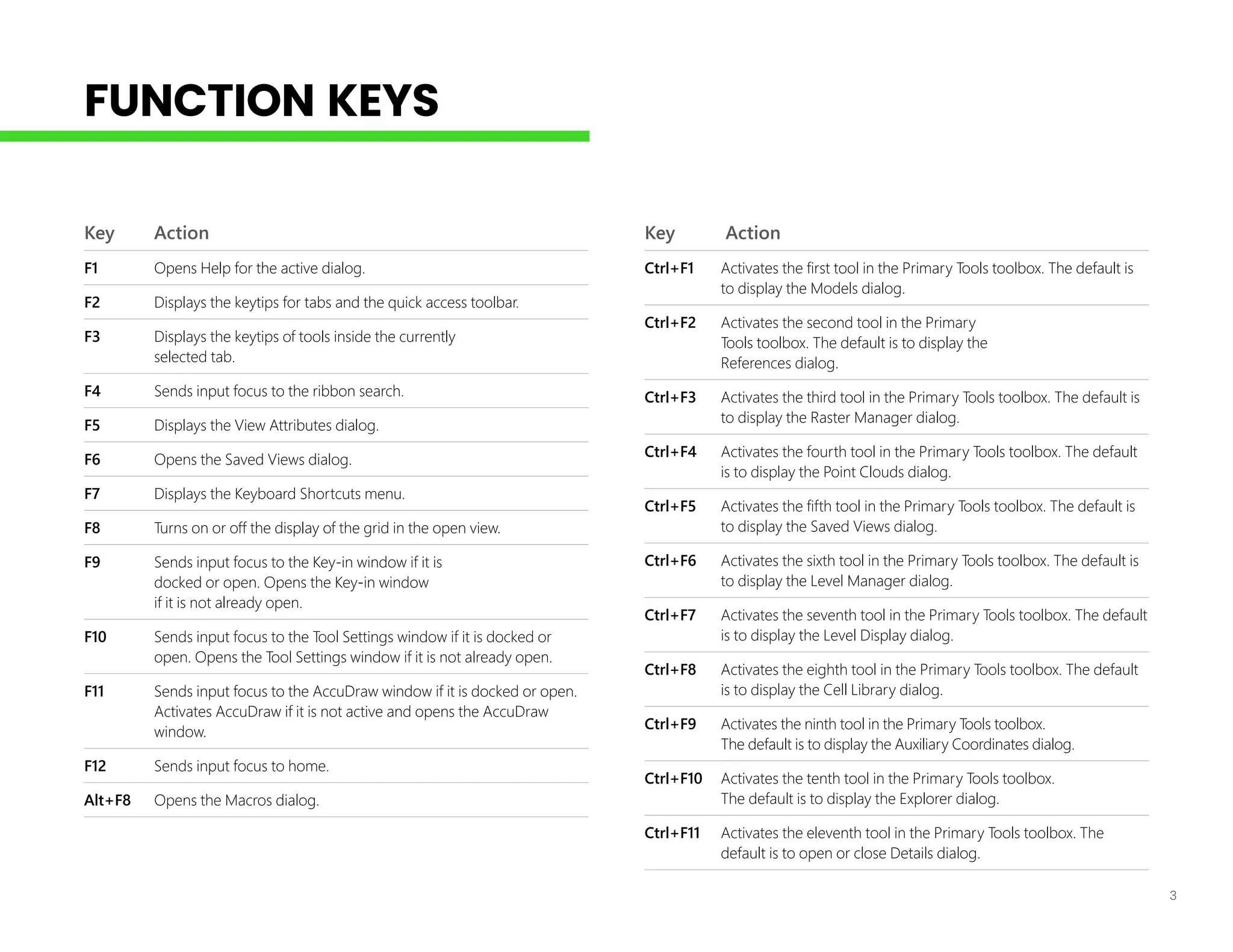
FUNCTION KEYS
Key Action
F1Opens Help for the active dialog.
F2 Displays the keytips for tabs and the quick access toolbar.
F3 Displays the keytips of tools inside the currently
selected tab.
F4 Sends input focus to the ribbon search.
F5 Displays the View Attributes dialog.
F6 Opens the Saved Views dialog.
F7 Displays the Keyboard Shortcuts menu.
F8 Turns on or off the display of the grid in the open view.
F9 Sends input focus to the Key-in window if it is
docked or open. Opens the Key-in window
if it is not already open.
F10 Sends input focus to the Tool Settings window if it is docked or
open. Opens the Tool Settings window if it is not already open.
F11 Sends input focus to the AccuDraw window if it is docked or open.
Activates AccuDraw if it is not active and opens the AccuDraw
window.
F12 Sends input focus to home.
Alt+F8 Opens the Macros dialog.
Key Action
Ctrl+F1 Activates the first tool in the Primary Tools toolbox. The default is
to display the Models dialog.
Ctrl+F2 Activates the second tool in the Primary
Tools toolbox. The default is to display the
References dialog.
Ctrl+F3 Activates the third tool in the Primary Tools toolbox. The default is
to display the Raster Manager dialog.
Ctrl+F4 Activates the fourth tool in the Primary Tools toolbox. The default
is to display the Point Clouds dialog.
Ctrl+F5 Activates the fifth tool in the Primary Tools toolbox. The default is
to display the Saved Views dialog.
Ctrl+F6 Activates the sixth tool in the Primary Tools toolbox. The default is
to display the Level Manager dialog.
Ctrl+F7 Activates the seventh tool in the Primary Tools toolbox. The default
is to display the Level Display dialog.
Ctrl+F8 Activates the eighth tool in the Primary Tools toolbox. The default
is to display the Cell Library dialog.
Ctrl+F9 Activates the ninth tool in the Primary Tools toolbox.
The default is to display the Auxiliary Coordinates dialog.
Ctrl+F10 Activates the tenth tool in the Primary Tools toolbox.
The default is to display the Explorer dialog.
Ctrl+F11 Activates the eleventh tool in the Primary Tools toolbox. The
default is to open or close Details dialog.
4.
Key Action
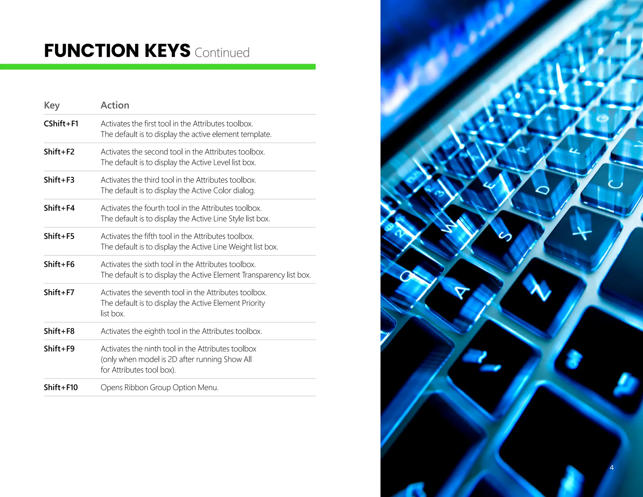
CShift+F1 Activatesthe first tool in the Attributes toolbox.
The default is to display the active element template.
Shift+F2 Activates the second tool in the Attributes toolbox.
The default is to display the Active Level list box.
Shift+F3 Activates the third tool in the Attributes toolbox.
The default is to display the Active Color dialog.
Shift+F4 Activates the fourth tool in the Attributes toolbox.
The default is to display the Active Line Style list box.
Shift+F5 Activates the fifth tool in the Attributes toolbox.
The default is to display the Active Line Weight list box.
Shift+F6 Activates the sixth tool in the Attributes toolbox.
The default is to display the Active Element Transparency list box.
Shift+F7 Activates the seventh tool in the Attributes toolbox.
The default is to display the Active Element Priority
list box.
Shift+F8 Activates the eighth tool in the Attributes toolbox.
Shift+F9 Activates the ninth tool in the Attributes toolbox
(only when model is 2D after running Show All
for Attributes tool box).
Shift+F10 Opens Ribbon Group Option Menu.
4
FUNCTION KEYS Continued
5.
5
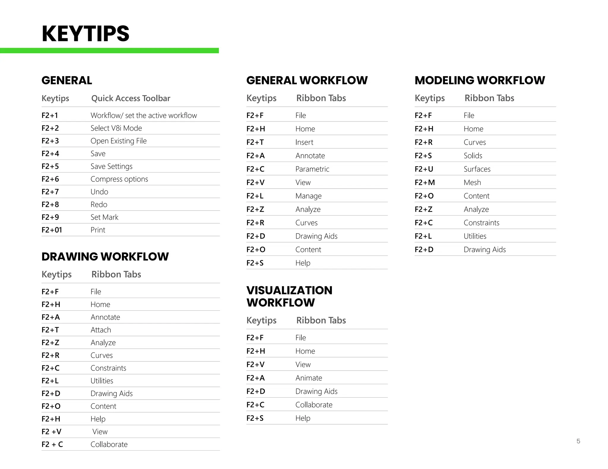
GENERAL
Keytips Quick AccessToolbar
F2+1 Workflow/ set the active workflow
F2+2 Select V8i Mode
F2+3 Open Existing File
F2+4 Save
F2+5 Save Settings
F2+6 Compress options
F2+7 Undo
F2+8 Redo
F2+9 Set Mark
F2+01 Print
DRAWING WORKFLOW
Keytips Ribbon Tabs
F2+F File
F2+H Home
F2+A Annotate
F2+T Attach
F2+Z Analyze
F2+R Curves
F2+C Constraints
F2+L Utilities
F2+D Drawing Aids
F2+O Content
F2+H Help
F2 +V View
F2 + C Collaborate
GENERAL WORKFLOW
Keytips Ribbon Tabs
F2+F File
F2+H Home
F2+T Insert
F2+A Annotate
F2+C Parametric
F2+V View
F2+L Manage
F2+Z Analyze
F2+R Curves
F2+D Drawing Aids
F2+O Content
F2+S Help
VISUALIZATION
WORKFLOW
Keytips Ribbon Tabs
F2+F File
F2+H Home
F2+V View
F2+A Animate
F2+D Drawing Aids
F2+C Collaborate
F2+S Help
MODELING WORKFLOW
Keytips Ribbon Tabs
F2+F File
F2+H Home
F2+R Curves
F2+S Solids
F2+U Surfaces
F2+M Mesh
F2+O Content
F2+Z Analyze
F2+C Constraints
F2+L Utilities
F2+D Drawing Aids
KEYTIPS
6.
6
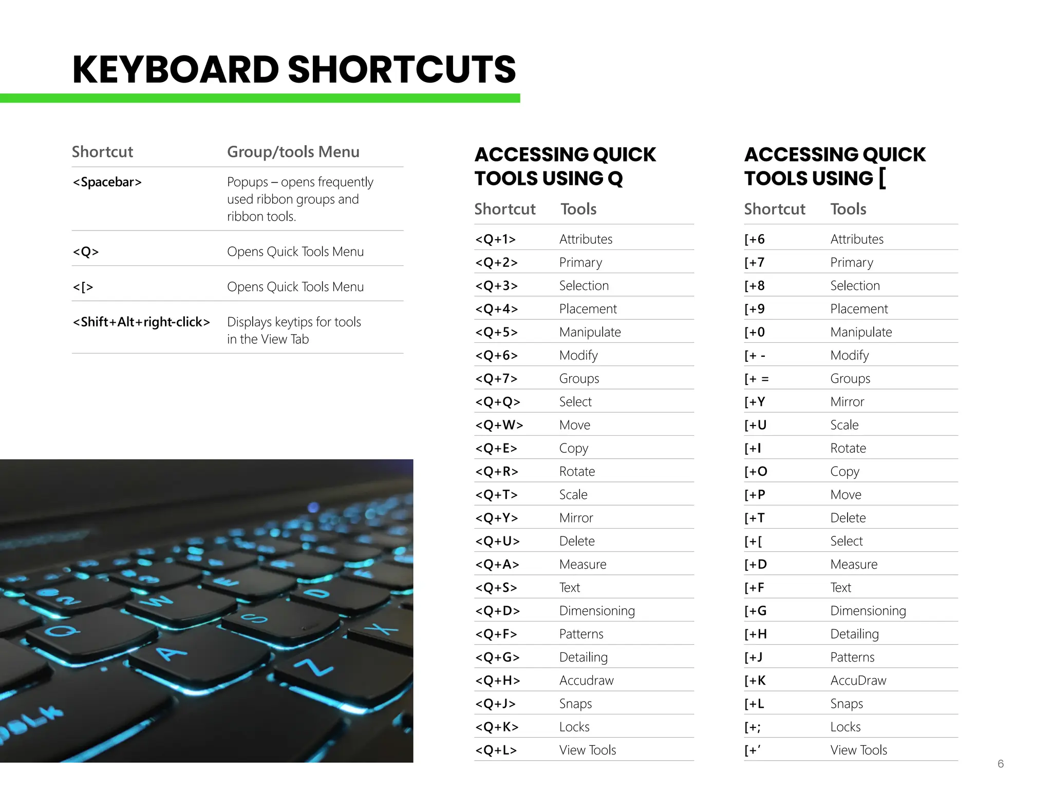
Shortcut Group/tools Menu
<Spacebar>Popups – opens frequently
used ribbon groups and
ribbon tools.
<Q> Opens Quick Tools Menu
<[> Opens Quick Tools Menu
<Shift+Alt+right-click> Displays keytips for tools
in the View Tab
ACCESSING QUICK
TOOLS USING Q
Shortcut Tools
<Q+1> Attributes
<Q+2> Primary
<Q+3> Selection
<Q+4> Placement
<Q+5> Manipulate
<Q+6> Modify
<Q+7> Groups
<Q+Q> Select
<Q+W> Move
<Q+E> Copy
<Q+R> Rotate
<Q+T> Scale
<Q+Y> Mirror
<Q+U> Delete
<Q+A> Measure
<Q+S> Text
<Q+D> Dimensioning
<Q+F> Patterns
<Q+G> Detailing
<Q+H> Accudraw
<Q+J> Snaps
<Q+K> Locks
<Q+L> View Tools
ACCESSING QUICK
TOOLS USING [
Shortcut Tools
[+6 Attributes
[+7 Primary
[+8 Selection
[+9 Placement
[+0 Manipulate
[+ - Modify
[+ = Groups
[+Y Mirror
[+U Scale
[+I Rotate
[+O Copy
[+P Move
[+T Delete
[+[ Select
[+D Measure
[+F Text
[+G Dimensioning
[+H Detailing
[+J Patterns
[+K AccuDraw
[+L Snaps
[+; Locks
[+’ View Tools
KEYBOARD SHORTCUTS
7.
7
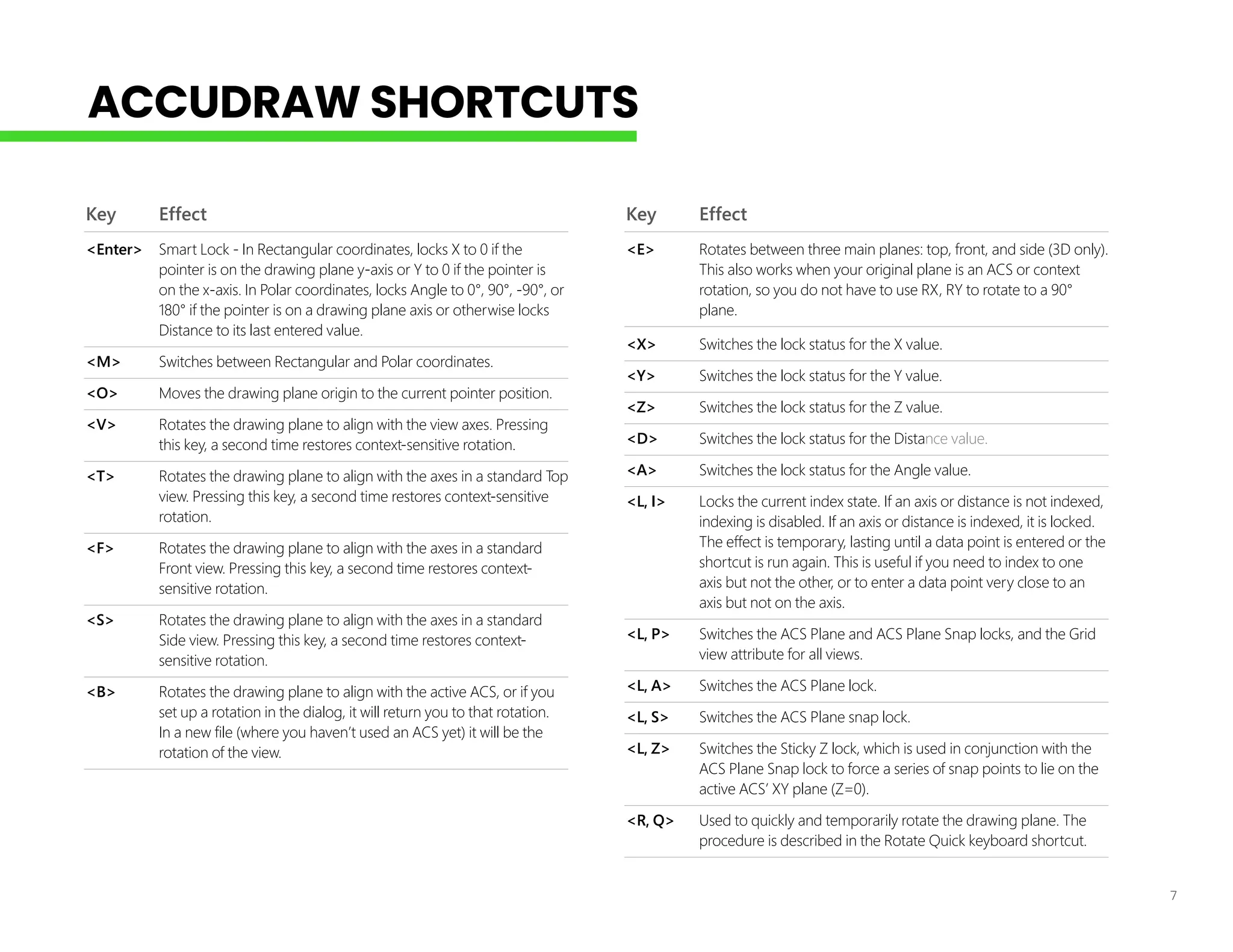
Key Effect
<Enter> SmartLock - In Rectangular coordinates, locks X to 0 if the
pointer is on the drawing plane y-axis or Y to 0 if the pointer is
on the x-axis. In Polar coordinates, locks Angle to 0°, 90°, -90°, or
180° if the pointer is on a drawing plane axis or otherwise locks
Distance to its last entered value.
<M> Switches between Rectangular and Polar coordinates.
<O> Moves the drawing plane origin to the current pointer position.
<V> Rotates the drawing plane to align with the view axes. Pressing
this key, a second time restores context-sensitive rotation.
<T> Rotates the drawing plane to align with the axes in a standard Top
view. Pressing this key, a second time restores context-sensitive
rotation.
<F> Rotates the drawing plane to align with the axes in a standard
Front view. Pressing this key, a second time restores context-
sensitive rotation.
<S> Rotates the drawing plane to align with the axes in a standard
Side view. Pressing this key, a second time restores context-
sensitive rotation.
<B> Rotates the drawing plane to align with the active ACS, or if you
set up a rotation in the dialog, it will return you to that rotation.
In a new file (where you haven’t used an ACS yet) it will be the
rotation of the view.
Key Effect
<E> Rotates between three main planes: top, front, and side (3D only).
This also works when your original plane is an ACS or context
rotation, so you do not have to use RX, RY to rotate to a 90°
plane.
<X> Switches the lock status for the X value.
<Y> Switches the lock status for the Y value.
<Z> Switches the lock status for the Z value.
<D> Switches the lock status for the Distance value.
<A> Switches the lock status for the Angle value.
<L, I> Locks the current index state. If an axis or distance is not indexed,
indexing is disabled. If an axis or distance is indexed, it is locked.
The effect is temporary, lasting until a data point is entered or the
shortcut is run again. This is useful if you need to index to one
axis but not the other, or to enter a data point very close to an
axis but not on the axis.
<L, P> Switches the ACS Plane and ACS Plane Snap locks, and the Grid
view attribute for all views.
<L, A> Switches the ACS Plane lock.
<L, S> Switches the ACS Plane snap lock.
<L, Z> Switches the Sticky Z lock, which is used in conjunction with the
ACS Plane Snap lock to force a series of snap points to lie on the
active ACS’ XY plane (Z=0).
<R, Q> Used to quickly and temporarily rotate the drawing plane. The
procedure is described in the Rotate Quick keyboard shortcut.
ACCUDRAW SHORTCUTS
8.
8
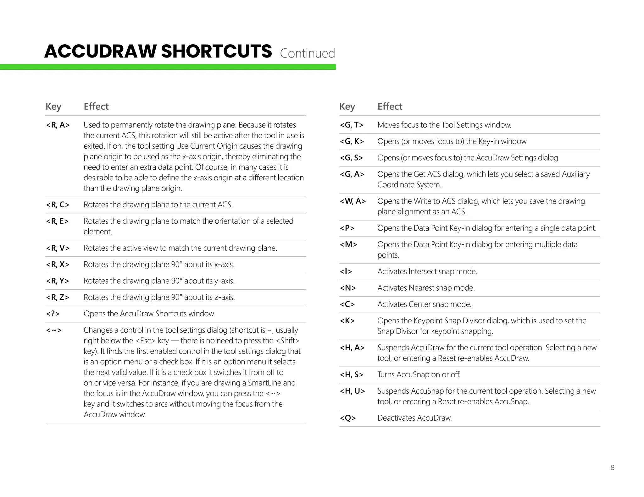
Key Effect
<R, A>Used to permanently rotate the drawing plane. Because it rotates
the current ACS, this rotation will still be active after the tool in use is
exited. If on, the tool setting Use Current Origin causes the drawing
plane origin to be used as the x-axis origin, thereby eliminating the
need to enter an extra data point. Of course, in many cases it is
desirable to be able to define the x-axis origin at a different location
than the drawing plane origin.
<R, C> Rotates the drawing plane to the current ACS.
<R, E> Rotates the drawing plane to match the orientation of a selected
element.
<R, V> Rotates the active view to match the current drawing plane.
<R, X> Rotates the drawing plane 90° about its x-axis.
<R, Y> Rotates the drawing plane 90° about its y-axis.
<R, Z> Rotates the drawing plane 90° about its z-axis.
<?> Opens the AccuDraw Shortcuts window.
<~> Changes a control in the tool settings dialog (shortcut is ~, usually
right below the <Esc> key — there is no need to press the <Shift>
key). It finds the first enabled control in the tool settings dialog that
is an option menu or a check box. If it is an option menu it selects
the next valid value. If it is a check box it switches it from off to
on or vice versa. For instance, if you are drawing a SmartLine and
the focus is in the AccuDraw window, you can press the <~>
key and it switches to arcs without moving the focus from the
AccuDraw window.
Key Effect
<G, T> Moves focus to the Tool Settings window.
<G, K> Opens (or moves focus to) the Key-in window
<G, S> Opens (or moves focus to) the AccuDraw Settings dialog
<G, A> Opens the Get ACS dialog, which lets you select a saved Auxiliary
Coordinate System.
<W, A> Opens the Write to ACS dialog, which lets you save the drawing
plane alignment as an ACS.
<P> Opens the Data Point Key-in dialog for entering a single data point.
<M> Opens the Data Point Key-in dialog for entering multiple data
points.
<I> Activates Intersect snap mode.
<N> Activates Nearest snap mode.
<C> Activates Center snap mode.
<K> Opens the Keypoint Snap Divisor dialog, which is used to set the
Snap Divisor for keypoint snapping.
<H, A> Suspends AccuDraw for the current tool operation. Selecting a new
tool, or entering a Reset re-enables AccuDraw.
<H, S> Turns AccuSnap on or off.
<H, U> Suspends AccuSnap for the current tool operation. Selecting a new
tool, or entering a Reset re-enables AccuSnap.
<Q> Deactivates AccuDraw.
ACCUDRAW SHORTCUTS Continued
9.
9
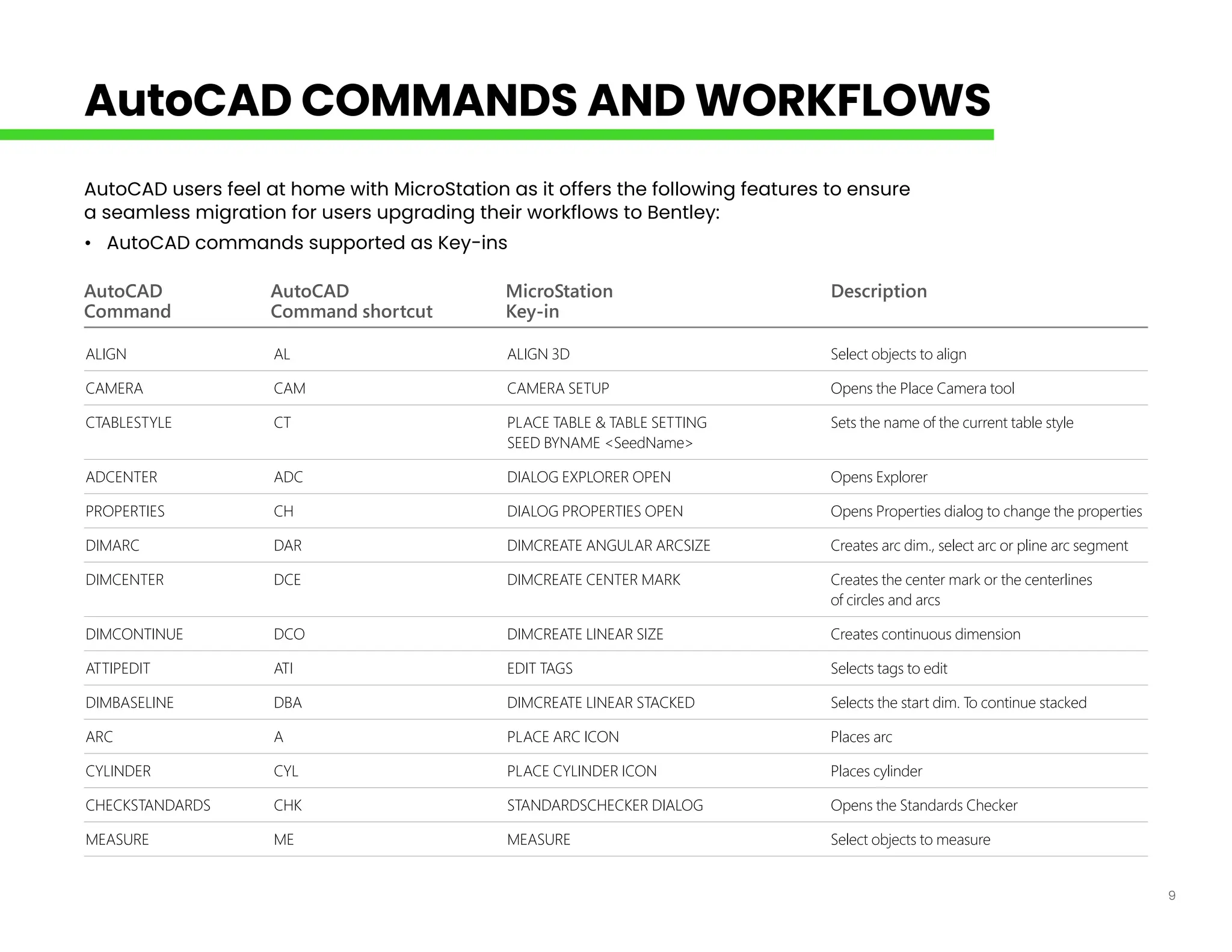
AutoCAD AutoCAD MicroStationDescription
Command Command shortcut Key-in
ALIGN AL ALIGN 3D Select objects to align
CAMERA CAM CAMERA SETUP Opens the Place Camera tool
CTABLESTYLE CT PLACE TABLE & TABLE SETTING Sets the name of the current table style
SEED BYNAME <SeedName>
ADCENTER ADC DIALOG EXPLORER OPEN Opens Explorer
PROPERTIES CH DIALOG PROPERTIES OPEN Opens Properties dialog to change the properties
DIMARC DAR DIMCREATE ANGULAR ARCSIZE Creates arc dim., select arc or pline arc segment
DIMCENTER DCE DIMCREATE CENTER MARK Creates the center mark or the centerlines
of circles and arcs
DIMCONTINUE DCO DIMCREATE LINEAR SIZE Creates continuous dimension
ATTIPEDIT ATI EDIT TAGS Selects tags to edit
DIMBASELINE DBA DIMCREATE LINEAR STACKED Selects the start dim. To continue stacked
ARC A PLACE ARC ICON Places arc
CYLINDER CYL PLACE CYLINDER ICON Places cylinder
CHECKSTANDARDS CHK STANDARDSCHECKER DIALOG Opens the Standards Checker
MEASURE ME MEASURE Select objects to measure
AutoCAD users feel at home with MicroStation as it offers the following features to ensure
a seamless migration for users upgrading their workflows to Bentley:
• AutoCAD commands supported as Key-ins
AutoCAD COMMANDS AND WORKFLOWS
10.
10
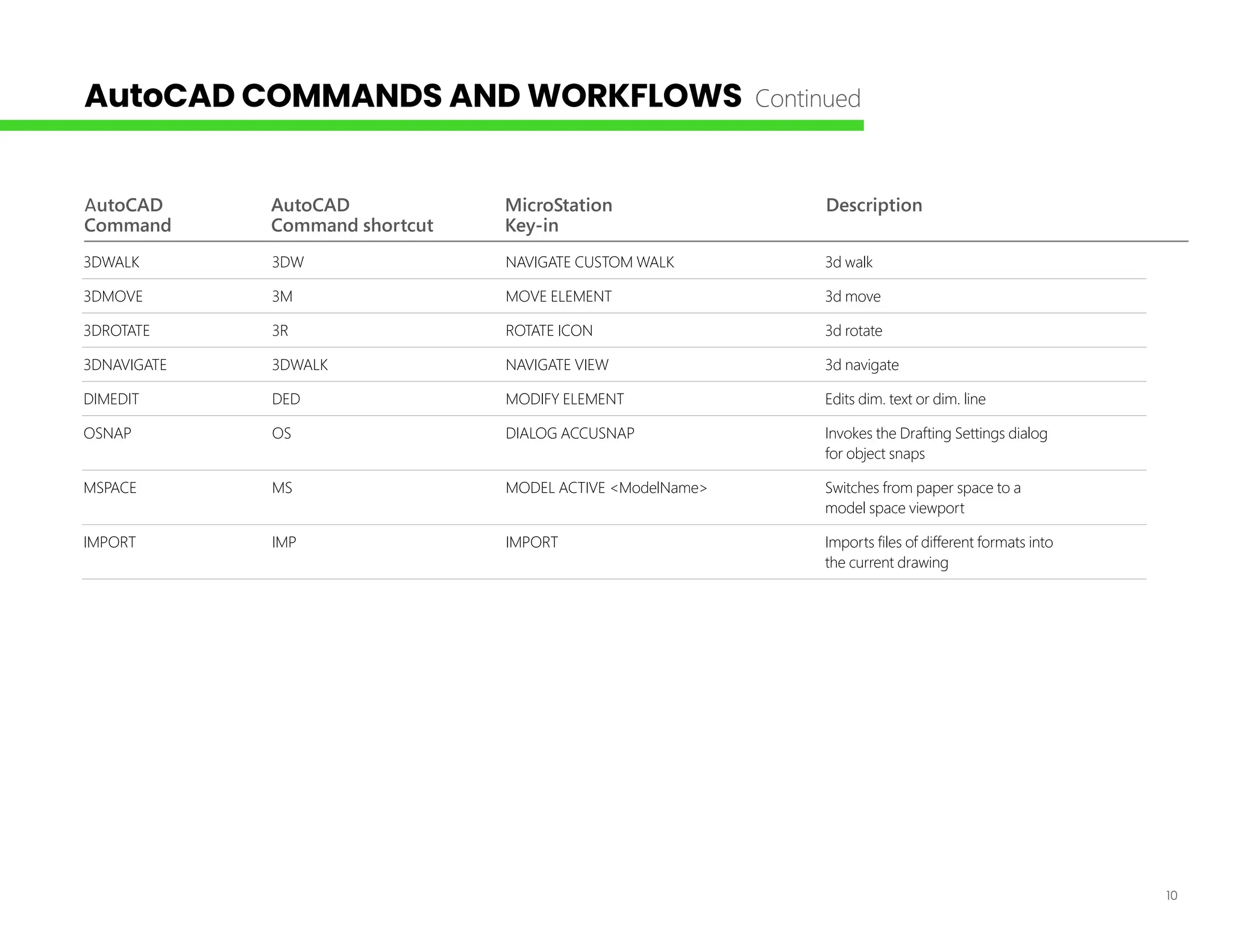
AutoCAD AutoCAD MicroStationDescription
Command Command shortcut Key-in
3DWALK 3DW NAVIGATE CUSTOM WALK 3d walk
3DMOVE 3M MOVE ELEMENT 3d move
3DROTATE 3R ROTATE ICON 3d rotate
3DNAVIGATE 3DWALK NAVIGATE VIEW 3d navigate
DIMEDIT DED MODIFY ELEMENT Edits dim. text or dim. line
OSNAP OS DIALOG ACCUSNAP Invokes the Drafting Settings dialog
for object snaps
MSPACE MS MODEL ACTIVE <ModelName> Switches from paper space to a
model space viewport
IMPORT IMP IMPORT Imports files of different formats into
the current drawing
AutoCAD COMMANDS AND WORKFLOWS Continued
11.
11
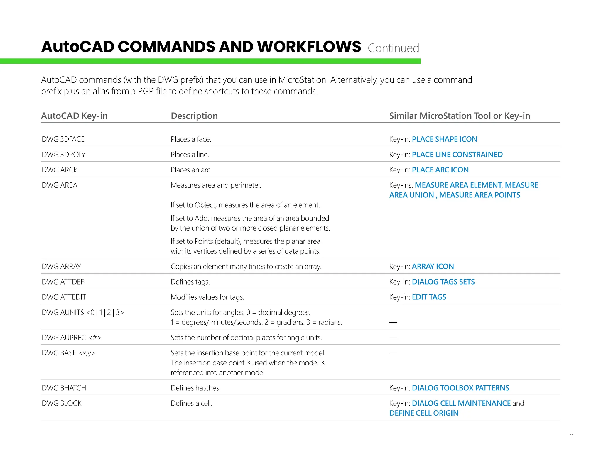
AutoCAD Key-in DescriptionSimilar MicroStation Tool or Key-in
DWG 3DFACE Places a face. Key-in: PLACE SHAPE ICON
DWG 3DPOLY Places a line. Key-in: PLACE LINE CONSTRAINED
DWG ARCk Places an arc. Key-in: PLACE ARC ICON
DWG AREA Measures area and perimeter. Key-ins: MEASURE AREA ELEMENT, MEASURE
AREA UNION , MEASURE AREA POINTS
If set to Object, measures the area of an element.
If set to Add, measures the area of an area bounded
by the union of two or more closed planar elements.
If set to Points (default), measures the planar area
with its vertices defined by a series of data points.
DWG ARRAY Copies an element many times to create an array. Key-in: ARRAY ICON
DWG ATTDEF Defines tags. Key-in: DIALOG TAGS SETS
DWG ATTEDIT Modifies values for tags. Key-in: EDIT TAGS
DWG AUNITS <0 | 1 | 2 | 3> Sets the units for angles. 0 = decimal degrees.
1 = degrees/minutes/seconds. 2 = gradians. 3 = radians. —
DWG AUPREC <#> Sets the number of decimal places for angle units. —
DWG BASE <x,y> Sets the insertion base point for the current model. —
The insertion base point is used when the model is
referenced into another model.
DWG BHATCH Defines hatches. Key-in: DIALOG TOOLBOX PATTERNS
DWG BLOCK Defines a cell. Key-in: DIALOG CELL MAINTENANCE and
DEFINE CELL ORIGIN
AutoCAD commands (with the DWG prefix) that you can use in MicroStation. Alternatively, you can use a command
prefix plus an alias from a PGP file to define shortcuts to these commands.
AutoCAD COMMANDS AND WORKFLOWS Continued
12.
12
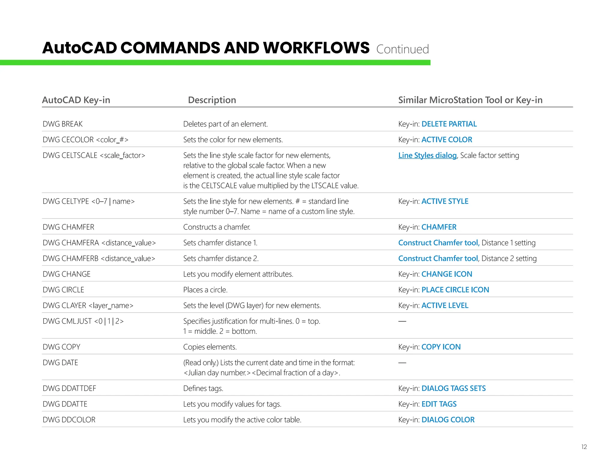
AutoCAD Key-in DescriptionSimilar MicroStation Tool or Key-in
DWG BREAK Deletes part of an element. Key-in: DELETE PARTIAL
DWG CECOLOR <color_#> Sets the color for new elements. Key-in: ACTIVE COLOR
DWG CELTSCALE <scale_factor> Sets the line style scale factor for new elements, Line Styles dialog, Scale factor setting
relative to the global scale factor. When a new
element is created, the actual line style scale factor
is the CELTSCALE value multiplied by the LTSCALE value.
DWG CELTYPE <0–7 | name> Sets the line style for new elements. # = standard line Key-in: ACTIVE STYLE
style number 0–7. Name = name of a custom line style.
DWG CHAMFER Constructs a chamfer. Key-in: CHAMFER
DWG CHAMFERA <distance_value> Sets chamfer distance 1. Construct Chamfer tool, Distance 1 setting
DWG CHAMFERB <distance_value> Sets chamfer distance 2. Construct Chamfer tool, Distance 2 setting
DWG CHANGE Lets you modify element attributes. Key-in: CHANGE ICON
DWG CIRCLE Places a circle. Key-in: PLACE CIRCLE ICON
DWG CLAYER <layer_name> Sets the level (DWG layer) for new elements. Key-in: ACTIVE LEVEL
DWG CMLJUST <0 | 1 | 2> Specifies justification for multi-lines. 0 = top. —
1 = middle. 2 = bottom.
DWG COPY Copies elements. Key-in: COPY ICON
DWG DATE (Read only.) Lists the current date and time in the format: —
<Julian day number.><Decimal fraction of a day>.
DWG DDATTDEF Defines tags. Key-in: DIALOG TAGS SETS
DWG DDATTE Lets you modify values for tags. Key-in: EDIT TAGS
DWG DDCOLOR Lets you modify the active color table. Key-in: DIALOG COLOR
AutoCAD COMMANDS AND WORKFLOWS Continued
13.
13
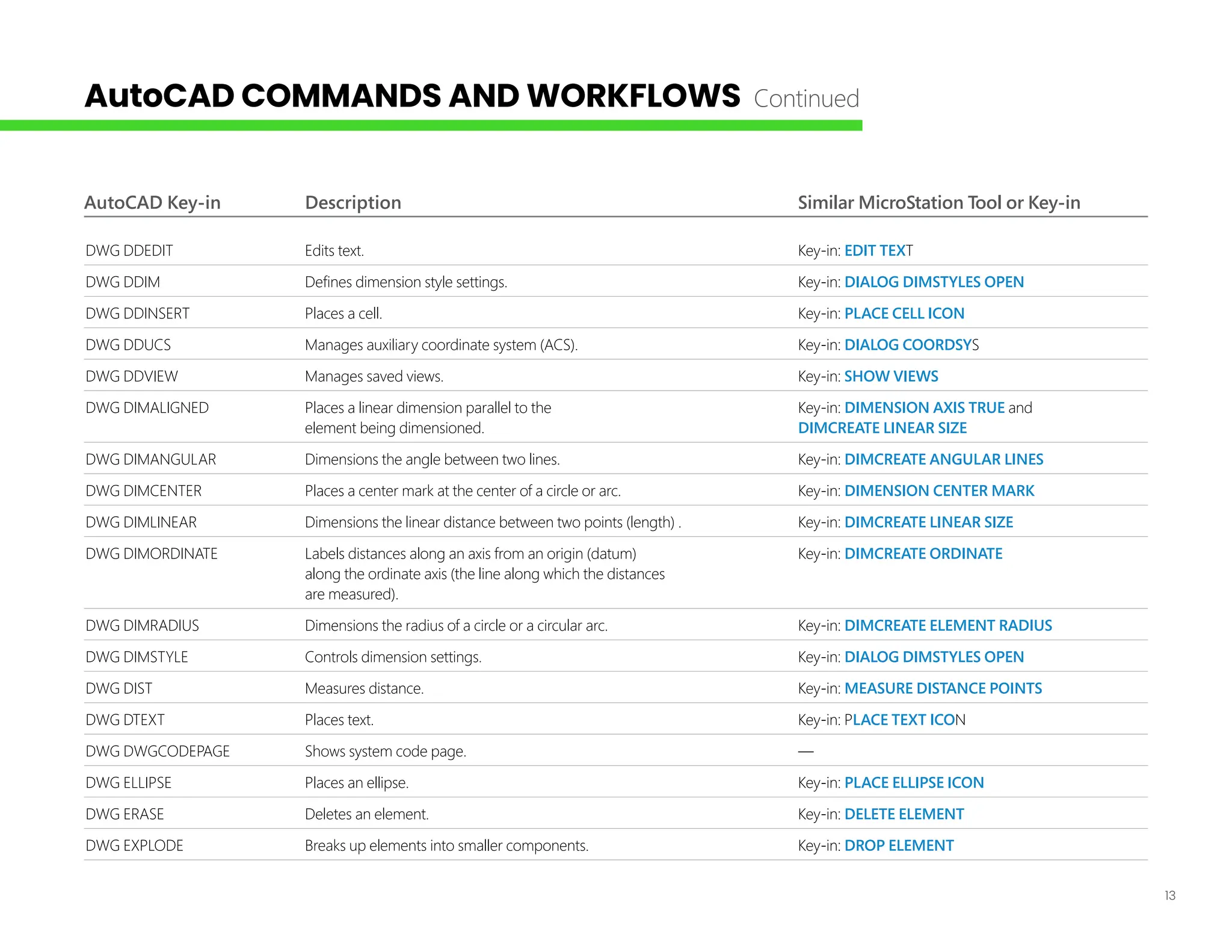
AutoCAD Key-in DescriptionSimilar MicroStation Tool or Key-in
DWG DDEDIT Edits text. Key-in: EDIT TEXT
DWG DDIM Defines dimension style settings. Key-in: DIALOG DIMSTYLES OPEN
DWG DDINSERT Places a cell. Key-in: PLACE CELL ICON
DWG DDUCS Manages auxiliary coordinate system (ACS). Key-in: DIALOG COORDSYS
DWG DDVIEW Manages saved views. Key-in: SHOW VIEWS
DWG DIMALIGNED Places a linear dimension parallel to the Key-in: DIMENSION AXIS TRUE and
element being dimensioned. DIMCREATE LINEAR SIZE
DWG DIMANGULAR Dimensions the angle between two lines. Key-in: DIMCREATE ANGULAR LINES
DWG DIMCENTER Places a center mark at the center of a circle or arc. Key-in: DIMENSION CENTER MARK
DWG DIMLINEAR Dimensions the linear distance between two points (length) . Key-in: DIMCREATE LINEAR SIZE
DWG DIMORDINATE Labels distances along an axis from an origin (datum) Key-in: DIMCREATE ORDINATE
along the ordinate axis (the line along which the distances
are measured).
DWG DIMRADIUS Dimensions the radius of a circle or a circular arc. Key-in: DIMCREATE ELEMENT RADIUS
DWG DIMSTYLE Controls dimension settings. Key-in: DIALOG DIMSTYLES OPEN
DWG DIST Measures distance. Key-in: MEASURE DISTANCE POINTS
DWG DTEXT Places text. Key-in: PLACE TEXT ICON
DWG DWGCODEPAGE Shows system code page. —
DWG ELLIPSE Places an ellipse. Key-in: PLACE ELLIPSE ICON
DWG ERASE Deletes an element. Key-in: DELETE ELEMENT
DWG EXPLODE Breaks up elements into smaller components. Key-in: DROP ELEMENT
AutoCAD COMMANDS AND WORKFLOWS Continued
14.
14
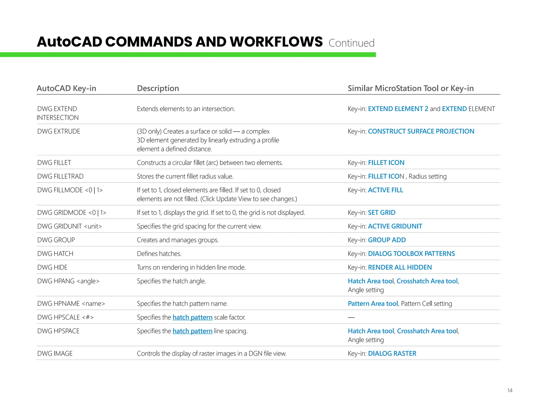
AutoCAD Key-in DescriptionSimilar MicroStation Tool or Key-in
DWG EXTEND Extends elements to an intersection. Key-in: EXTEND ELEMENT 2 and EXTEND ELEMENT
INTERSECTION
DWG EXTRUDE (3D only) Creates a surface or solid — a complex Key-in: CONSTRUCT SURFACE PROJECTION
3D element generated by linearly extruding a profile
element a defined distance.
DWG FILLET Constructs a circular fillet (arc) between two elements. Key-in: FILLET ICON
DWG FILLETRAD Stores the current fillet radius value. Key-in: FILLET ICON , Radius setting
DWG FILLMODE <0 | 1> If set to 1, closed elements are filled. If set to 0, closed Key-in: ACTIVE FILL
elements are not filled. (Click Update View to see changes.)
DWG GRIDMODE <0 | 1> If set to 1, displays the grid. If set to 0, the grid is not displayed. Key-in: SET GRID
DWG GRIDUNIT <unit> Specifies the grid spacing for the current view. Key-in: ACTIVE GRIDUNIT
DWG GROUP Creates and manages groups. Key-in: GROUP ADD
DWG HATCH Defines hatches. Key-in: DIALOG TOOLBOX PATTERNS
DWG HIDE Turns on rendering in hidden line mode. Key-in: RENDER ALL HIDDEN
DWG HPANG <angle> Specifies the hatch angle. Hatch Area tool, Crosshatch Area tool,
Angle setting
DWG HPNAME <name> Specifies the hatch pattern name. Pattern Area tool, Pattern Cell setting
DWG HPSCALE <#> Specifies the hatch pattern scale factor. —
DWG HPSPACE Specifies the hatch pattern line spacing. Hatch Area tool, Crosshatch Area tool,
Angle setting
DWG IMAGE Controls the display of raster images in a DGN file view. Key-in: DIALOG RASTER
AutoCAD COMMANDS AND WORKFLOWS Continued
15.
15
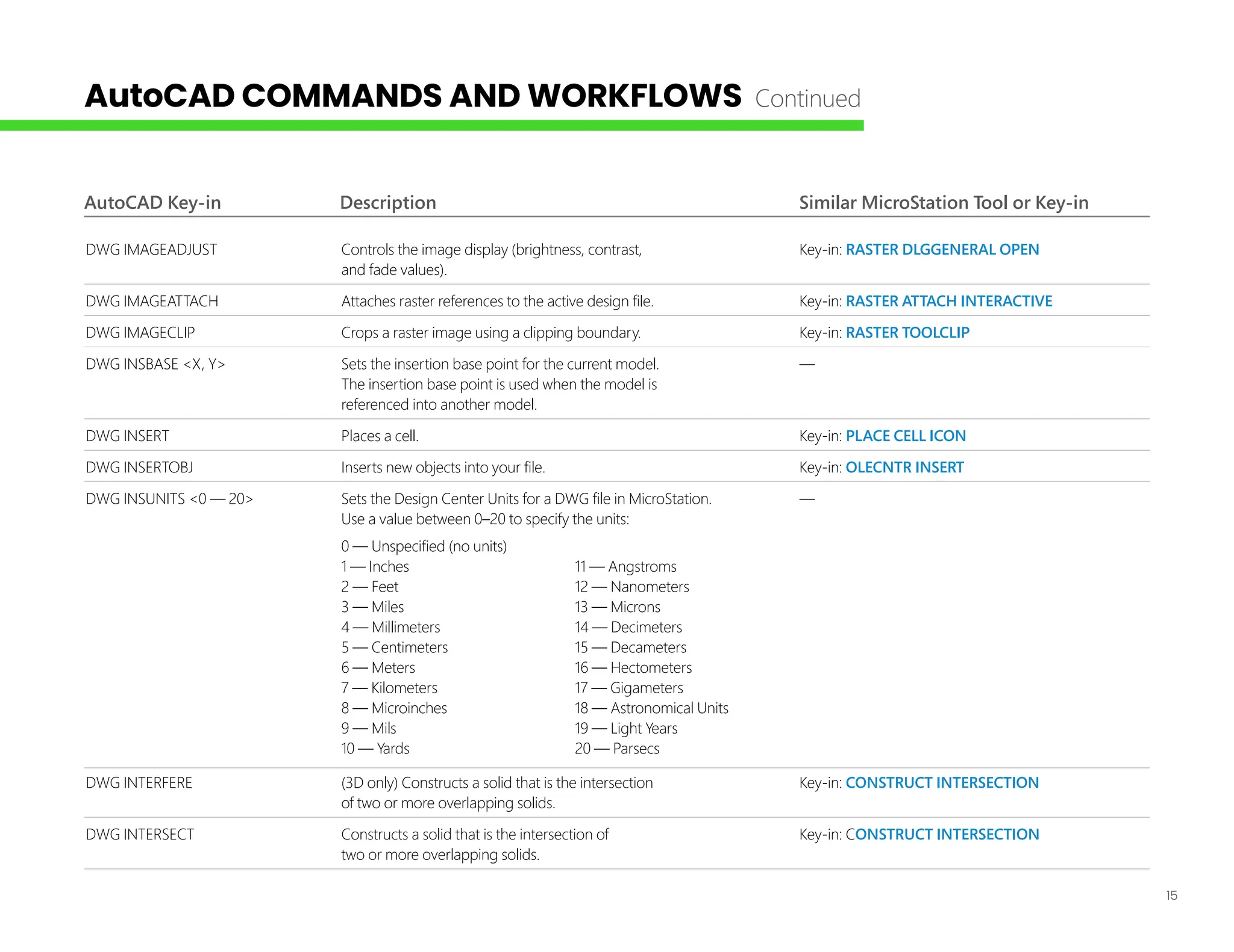
AutoCAD Key-in DescriptionSimilar MicroStation Tool or Key-in
DWG IMAGEADJUST Controls the image display (brightness, contrast, Key-in: RASTER DLGGENERAL OPEN
and fade values).
DWG IMAGEATTACH Attaches raster references to the active design file. Key-in: RASTER ATTACH INTERACTIVE
DWG IMAGECLIP Crops a raster image using a clipping boundary. Key-in: RASTER TOOLCLIP
DWG INSBASE <X, Y> Sets the insertion base point for the current model. —
The insertion base point is used when the model is
referenced into another model.
DWG INSERT Places a cell. Key-in: PLACE CELL ICON
DWG INSERTOBJ Inserts new objects into your file. Key-in: OLECNTR INSERT
DWG INSUNITS <0 — 20> Sets the Design Center Units for a DWG file in MicroStation. —
Use a value between 0–20 to specify the units:
0 — Unspecified (no units)
1 — Inches 11 — Angstroms
2 — Feet 12 — Nanometers
3 — Miles 13 — Microns
4 — Millimeters 14 — Decimeters
5 — Centimeters 15 — Decameters
6 — Meters 16 — Hectometers
7 — Kilometers 17 — Gigameters
8 — Microinches 18 — Astronomical Units
9 — Mils 19 — Light Years
10 — Yards 20 — Parsecs
DWG INTERFERE (3D only) Constructs a solid that is the intersection Key-in: CONSTRUCT INTERSECTION
of two or more overlapping solids.
DWG INTERSECT Constructs a solid that is the intersection of Key-in: CONSTRUCT INTERSECTION
two or more overlapping solids.
AutoCAD COMMANDS AND WORKFLOWS Continued
16.
16
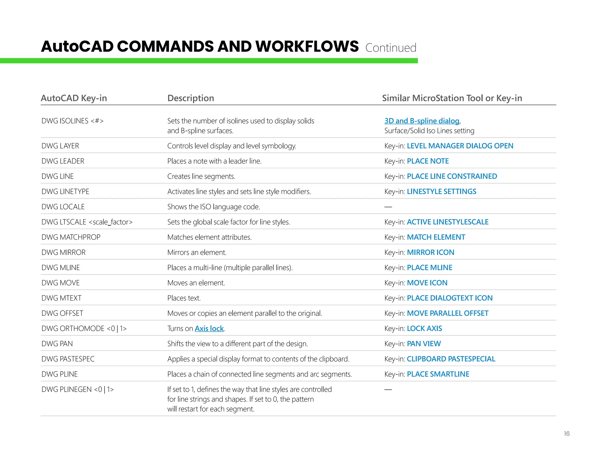
AutoCAD Key-in DescriptionSimilar MicroStation Tool or Key-in
DWG ISOLINES <#> Sets the number of isolines used to display solids 3D and B-spline dialog,
and B-spline surfaces. Surface/Solid Iso Lines setting
DWG LAYER Controls level display and level symbology. Key-in: LEVEL MANAGER DIALOG OPEN
DWG LEADER Places a note with a leader line. Key-in: PLACE NOTE
DWG LINE Creates line segments. Key-in: PLACE LINE CONSTRAINED
DWG LINETYPE Activates line styles and sets line style modifiers. Key-in: LINESTYLE SETTINGS
DWG LOCALE Shows the ISO language code. —
DWG LTSCALE <scale_factor> Sets the global scale factor for line styles. Key-in: ACTIVE LINESTYLESCALE
DWG MATCHPROP Matches element attributes. Key-in: MATCH ELEMENT
DWG MIRROR Mirrors an element. Key-in: MIRROR ICON
DWG MLINE Places a multi-line (multiple parallel lines). Key-in: PLACE MLINE
DWG MOVE Moves an element. Key-in: MOVE ICON
DWG MTEXT Places text. Key-in: PLACE DIALOGTEXT ICON
DWG OFFSET Moves or copies an element parallel to the original. Key-in: MOVE PARALLEL OFFSET
DWG ORTHOMODE <0 | 1> Turns on Axis lock. Key-in: LOCK AXIS
DWG PAN Shifts the view to a different part of the design. Key-in: PAN VIEW
DWG PASTESPEC Applies a special display format to contents of the clipboard. Key-in: CLIPBOARD PASTESPECIAL
DWG PLINE Places a chain of connected line segments and arc segments. Key-in: PLACE SMARTLINE
DWG PLINEGEN <0 | 1> If set to 1, defines the way that line styles are controlled —
for line strings and shapes. If set to 0, the pattern
will restart for each segment.
AutoCAD COMMANDS AND WORKFLOWS Continued
17.
17
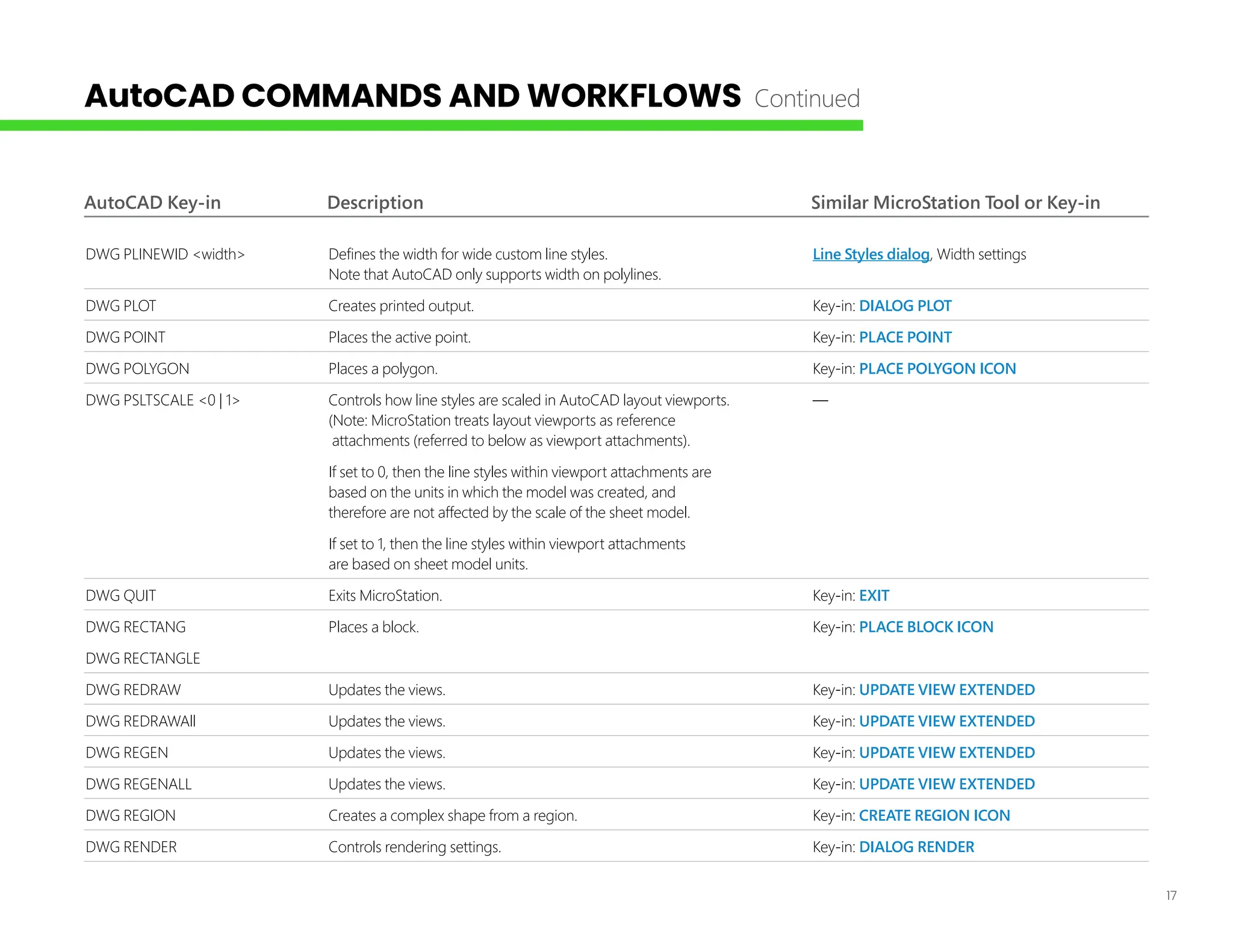
AutoCAD Key-in DescriptionSimilar MicroStation Tool or Key-in
DWG PLINEWID <width> Defines the width for wide custom line styles. Line Styles dialog, Width settings
Note that AutoCAD only supports width on polylines.
DWG PLOT Creates printed output. Key-in: DIALOG PLOT
DWG POINT Places the active point. Key-in: PLACE POINT
DWG POLYGON Places a polygon. Key-in: PLACE POLYGON ICON
DWG PSLTSCALE <0 | 1> Controls how line styles are scaled in AutoCAD layout viewports. —
(Note: MicroStation treats layout viewports as reference
attachments (referred to below as viewport attachments).
If set to 0, then the line styles within viewport attachments are
based on the units in which the model was created, and
therefore are not affected by the scale of the sheet model.
If set to 1, then the line styles within viewport attachments
are based on sheet model units.
DWG QUIT Exits MicroStation. Key-in: EXIT
DWG RECTANG Places a block. Key-in: PLACE BLOCK ICON
DWG RECTANGLE
DWG REDRAW Updates the views. Key-in: UPDATE VIEW EXTENDED
DWG REDRAWAll Updates the views. Key-in: UPDATE VIEW EXTENDED
DWG REGEN Updates the views. Key-in: UPDATE VIEW EXTENDED
DWG REGENALL Updates the views. Key-in: UPDATE VIEW EXTENDED
DWG REGION Creates a complex shape from a region. Key-in: CREATE REGION ICON
DWG RENDER Controls rendering settings. Key-in: DIALOG RENDER
AutoCAD COMMANDS AND WORKFLOWS Continued
18.
18
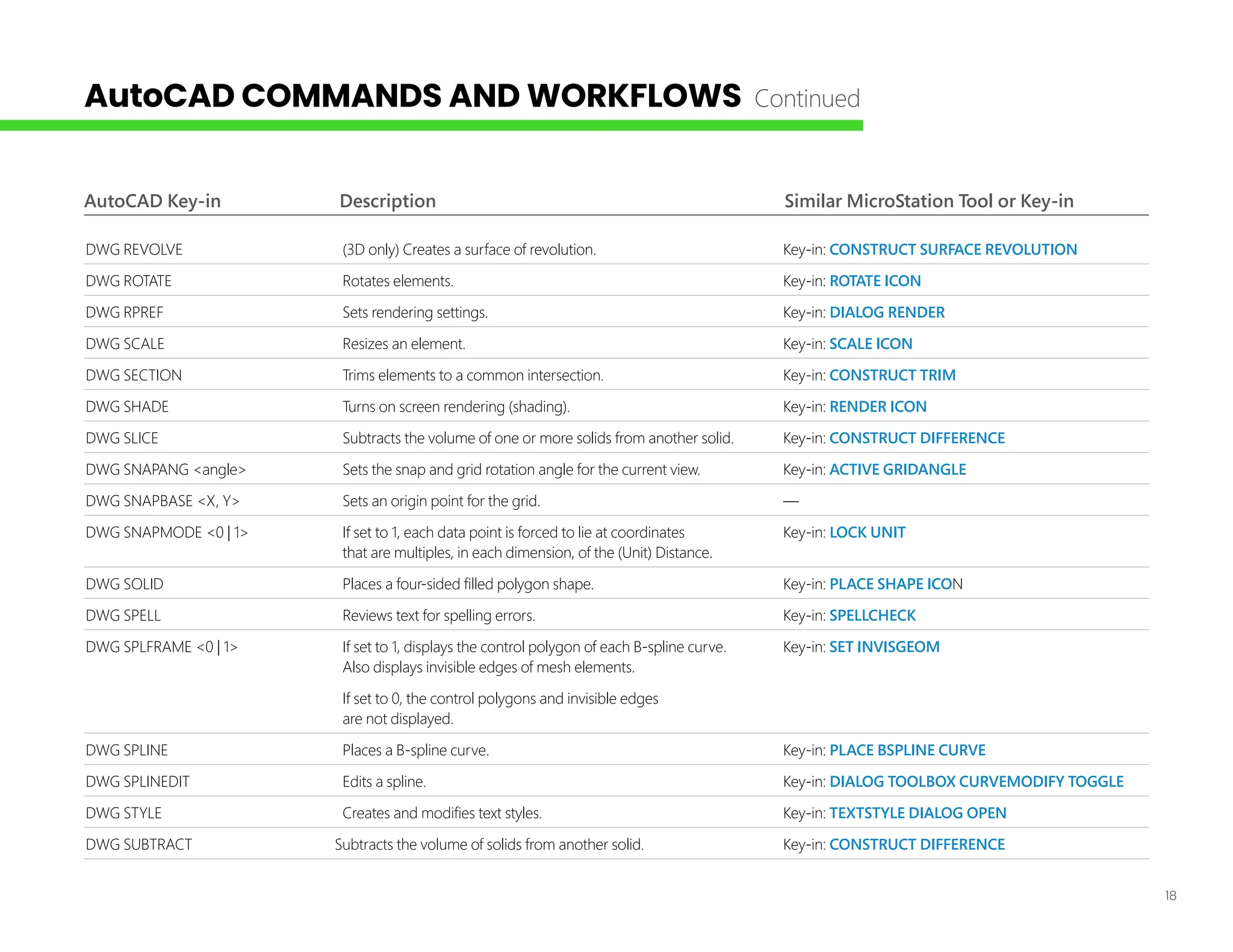
AutoCAD Key-in DescriptionSimilar MicroStation Tool or Key-in
DWG REVOLVE (3D only) Creates a surface of revolution. Key-in: CONSTRUCT SURFACE REVOLUTION
DWG ROTATE Rotates elements. Key-in: ROTATE ICON
DWG RPREF Sets rendering settings. Key-in: DIALOG RENDER
DWG SCALE Resizes an element. Key-in: SCALE ICON
DWG SECTION Trims elements to a common intersection. Key-in: CONSTRUCT TRIM
DWG SHADE Turns on screen rendering (shading). Key-in: RENDER ICON
DWG SLICE Subtracts the volume of one or more solids from another solid. Key-in: CONSTRUCT DIFFERENCE
DWG SNAPANG <angle> Sets the snap and grid rotation angle for the current view. Key-in: ACTIVE GRIDANGLE
DWG SNAPBASE <X, Y> Sets an origin point for the grid. —
DWG SNAPMODE <0 | 1> If set to 1, each data point is forced to lie at coordinates Key-in: LOCK UNIT
that are multiples, in each dimension, of the (Unit) Distance.
DWG SOLID Places a four-sided filled polygon shape. Key-in: PLACE SHAPE ICON
DWG SPELL Reviews text for spelling errors. Key-in: SPELLCHECK
DWG SPLFRAME <0 | 1> If set to 1, displays the control polygon of each B-spline curve. Key-in: SET INVISGEOM
Also displays invisible edges of mesh elements.
If set to 0, the control polygons and invisible edges
are not displayed.
DWG SPLINE Places a B-spline curve. Key-in: PLACE BSPLINE CURVE
DWG SPLINEDIT Edits a spline. Key-in: DIALOG TOOLBOX CURVEMODIFY TOGGLE
DWG STYLE Creates and modifies text styles. Key-in: TEXTSTYLE DIALOG OPEN
DWG SUBTRACT Subtracts the volume of solids from another solid. Key-in: CONSTRUCT DIFFERENCE
AutoCAD COMMANDS AND WORKFLOWS Continued
19.
19
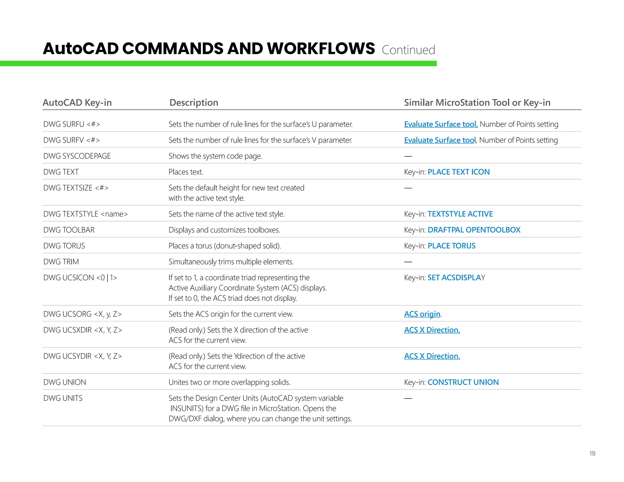
AutoCAD Key-in DescriptionSimilar MicroStation Tool or Key-in
DWG SURFU <#> Sets the number of rule lines for the surface’s U parameter. Evaluate Surface tool, Number of Points setting
DWG SURFV <#> Sets the number of rule lines for the surface’s V parameter. Evaluate Surface tool, Number of Points setting
DWG SYSCODEPAGE Shows the system code page. —
DWG TEXT Places text. Key-in: PLACE TEXT ICON
DWG TEXTSIZE <#> Sets the default height for new text created —
with the active text style.
DWG TEXTSTYLE <name> Sets the name of the active text style. Key-in: TEXTSTYLE ACTIVE
DWG TOOLBAR Displays and customizes toolboxes. Key-in: DRAFTPAL OPENTOOLBOX
DWG TORUS Places a torus (donut-shaped solid). Key-in: PLACE TORUS
DWG TRIM Simultaneously trims multiple elements. —
DWG UCSICON <0 | 1> If set to 1, a coordinate triad representing the Key-in: SET ACSDISPLAY
Active Auxiliary Coordinate System (ACS) displays.
If set to 0, the ACS triad does not display.
DWG UCSORG <X, y, Z> Sets the ACS origin for the current view. ACS origin.
DWG UCSXDIR <X, Y, Z> (Read only.) Sets the X direction of the active ACS X Direction.
ACS for the current view.
DWG UCSYDIR <X, Y, Z> (Read only.) Sets the Ydirection of the active ACS X Direction.
ACS for the current view.
DWG UNION Unites two or more overlapping solids. Key-in: CONSTRUCT UNION
DWG UNITS Sets the Design Center Units (AutoCAD system variable —
INSUNITS) for a DWG file in MicroStation. Opens the
DWG/DXF dialog, where you can change the unit settings.
AutoCAD COMMANDS AND WORKFLOWS Continued
20.
20
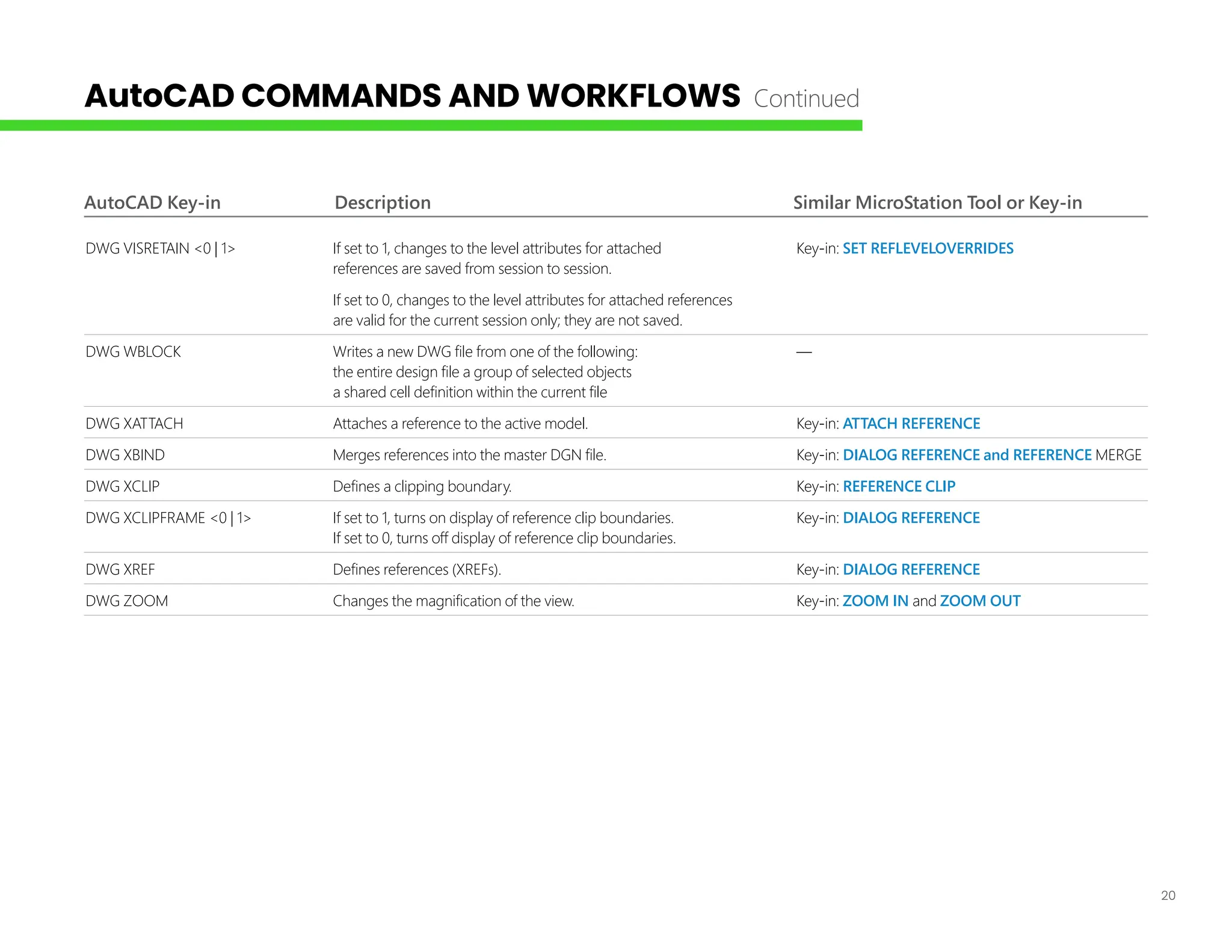
AutoCAD Key-in DescriptionSimilar MicroStation Tool or Key-in
DWG VISRETAIN <0 | 1> If set to 1, changes to the level attributes for attached Key-in: SET REFLEVELOVERRIDES
references are saved from session to session.
If set to 0, changes to the level attributes for attached references
are valid for the current session only; they are not saved.
DWG WBLOCK Writes a new DWG file from one of the following: —
the entire design file a group of selected objects
a shared cell definition within the current file
DWG XATTACH Attaches a reference to the active model. Key-in: ATTACH REFERENCE
DWG XBIND Merges references into the master DGN file. Key-in: DIALOG REFERENCE and REFERENCE MERGE
DWG XCLIP Defines a clipping boundary. Key-in: REFERENCE CLIP
DWG XCLIPFRAME <0 | 1> If set to 1, turns on display of reference clip boundaries. Key-in: DIALOG REFERENCE
If set to 0, turns off display of reference clip boundaries.
DWG XREF Defines references (XREFs). Key-in: DIALOG REFERENCE
DWG ZOOM Changes the magnification of the view. Key-in: ZOOM IN and ZOOM OUT
AutoCAD COMMANDS AND WORKFLOWS Continued
21.
THE DARK THEME
TheDark themed user interface in combination with the General workflow makes the MicroStation UI even more familiar for users newly
migrating from AutoCAD. You can enable the Dark Theme in the File > Settings > User Preferences > Look and Feel category.
DWG WORKSET WIZARD
The DWG WorkSet Wizard helps you create a WorkSet for your Projects using DWG and migrate folders to CONNECT Configuration.
REALDWG 2021 SUPPORT
MicroStation has updated RealDWG Libraries to support RealDWG 2021, for utmost compatibility.
The General workflow in MicroStation offers a user interface that is analogous to the AutoCAD UI. You can select General
from the workflow drop-down menu in the Quick Access Toolbar to switch to this workflow.
For more information about using MicroStation visit the
MicroStation page of Bentley Communities
21
THE GENERAL WORKFLOW
2023 Bentley Systems, Incorporated. Accudraw, Bentley, the Bentley logo, and MicroStation are either registered or unregistered trademarks or service marks of Bentley
Systems, Incorporated, or one of its direct or indirect wholly owned subsidiaries. Other brands and product names are trademarks of their respective owners. 12.23