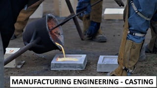
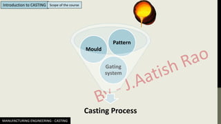
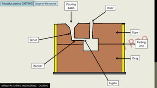
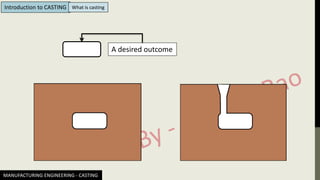
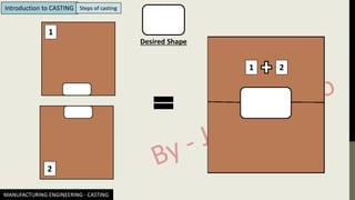
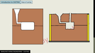
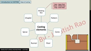
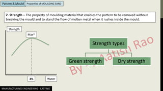
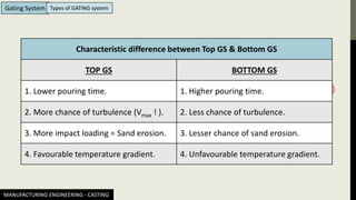
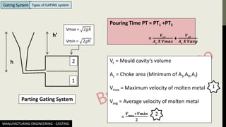
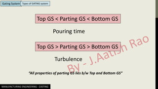
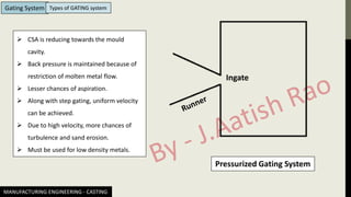
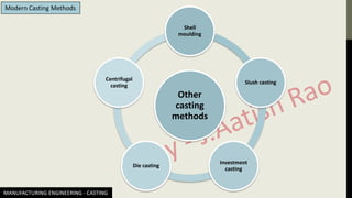
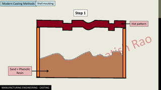
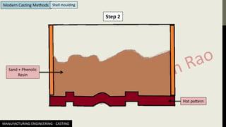
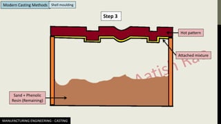
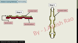
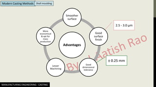
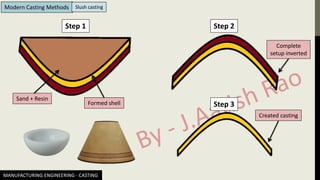
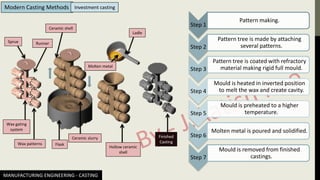
Workshop Technology OR Machine Shop Theory
Heat And Mass Transfer – HMT
Production planning and control – PPC
Applied Mechanics Or Engineering Mechanics
Engineering Materials or Material Science
Engineering Thermodynamics Or Applied Thermodynamics
IC Engines
Engineering Mathematics - Numerical Analysis & more
Strength of material OR Mechanics of solid
@thelearninghub2019 @essentialamalgame @jaatishrao
MANUFACTURING ENGINEERING - CASTING
Introduction to CASTING Scope of the course
Casting Process
Gating
system
Mould
Pattern
MANUFACTURING ENGINEERING - CASTING
Introduction to CASTING Scope of the course Pouring
Basin Riser
Sprue
Runner
Ingate
Cope
Parting
Line
Drag
MANUFACTURING ENGINEERING - CASTING
Introduction to CASTING Scope of the course
SN Section/Unit Contents
1. Introduction What is casting & steps involved in casting process.
2. Pattern and Mould
Types of pattern material, Pattern allowances, Types of pattern,
Types of sand mould, Binders & Additives, Properties of
moulding sand, Methods of mould making
3. Gating system
Casting elements, Accessories, Gating ratio, Aspiration effect,
Cores & Chaplets, Solidification time, Riser design
4. Modern casting methods
Shell moulding, Slush casting, Investment casting, Die casting
method, Centrifugal casting
5. Miscellaneous Grain behaviour in casting, Types of casting defects
MANUFACTURING ENGINEERING - CASTING
Introduction to CASTING What is casting
Ice Making Metal Casting
Raw Material – Water
Raw Material – Molten
metal
Equipment – Ice tray Equipment – Mould
Output – Ice cube
Output – Casted
component
MANUFACTURING ENGINEERING - CASTING
Introduction to CASTING
What is casting
Casting is a process in which molten metal is poured into a cavity whose shape is similar to the
desired casted component. This casted component is obtained by breaking the mould.
Advantages Disadvantages
• Cheap and easy.
• Small to large components can be
manufactured.
• Can make complicated shapes.
❖ Defects almost impossible to
completely avoid.
❖ Surface finish is not good.
❖ Less dimensional accuracy.
❖ Further machining is required almost
all the time.
MANUFACTURING ENGINEERING - CASTING
Introduction to CASTING What is casting
MANUFACTURING ENGINEERING - CASTING
Introduction to CASTING
A desired outcome
What is casting
MANUFACTURING ENGINEERING - CASTING
1
2
1 2
Desired Shape
Introduction to CASTING Steps of casting
MANUFACTURING ENGINEERING - CASTING
Introduction to CASTING Steps of casting
Casting
elements
Molding
Box
Pattern
Cores
Riser
Runner
Sprue
Chaplet
Cope – Upper Flask
Cheek – Middle Flask
Drag – Lower flask
MANUFACTURING ENGINEERING - CASTING
Introduction to CASTING Steps of casting
MANUFACTURING ENGINEERING - CASTING
Pattern & Mould Types of Pattern Material
A pattern is an element used for making cavities in the mould, into which molten metal
can be poured to produce a desired casting.
It is not an exact replica of the casting desired. It is slightly larger. This is due to various
allowances (Shrinkage allowance, Machining allowance etc.)
Due to various allowances (Shrinkage, machining, draft, shake
etc;) and several projections (called core prints), it is slightly
larger in size than the casting.
MANUFACTURING ENGINEERING - CASTING
Pattern & Mould Types of Pattern Material
Wood
Metal
Plastic
Wax
Mercury
MANUFACTURING ENGINEERING - CASTING
Pattern & Mould Types of Pattern Material
Wooden Pattern
The wood used for pattern making should be properly dried and seasoned.
It should not contain more than 10% moisture to avoid warping and
distortion during subsequent drying.
Advantages Disadvantages
Light in weight Inherently non-uniform structure.
Inexpensive Poor wear resistance
Good workability Poor abrasion resistance
Ease of gluing and joining Rough handling a big NO
Varnishes and paints easily holds Gives off moisture
Can be repaired easily Seasoning is mandatory
MANUFACTURING ENGINEERING - CASTING
Pattern & Mould Types of Pattern Material
Metal Pattern
A metal pattern can be either cast from a master wooden pattern or maybe
machined by traditional and modern machining processes. These kind of
patterns are mostly used in casting.
Advantages Disadvantages
More durable than wood Expensive as compared to wood
Size accuracy Not easily repairable
Have a smooth surface Heavier
Do not deform in storage Can get rusted (Ferrous patterns)
Resistance to wear and abrasion
Rough handling
MANUFACTURING ENGINEERING - CASTING
Pattern & Mould Types of Pattern Material
Metal Pattern
CI Brass Al White Metal
MANUFACTURING ENGINEERING - CASTING
Pattern & Mould Types of Pattern Material
Plastic Pattern
❖ Facilitates the production process.
❖ More economical.
❖ Highly resistant to corrosion.
❖ Moulding sand sticks less to plastic than wood.
❖ NO Moisture absorption.
❖ Smooth surface.
❖ Lighter and stronger than wood.
❖ Dimensionally stable.
MANUFACTURING ENGINEERING - CASTING
Pattern & Mould Types of Pattern Material
Wax Pattern
❖ Very easy to change the shape.
❖ Even works for very complicated patterns.
❖ Easily to be removed (Entire mould is heated to remove it once cavity is
formed successfully).
❖ Surface of pattern material (Wax) is smooth = Cavity generated will have
a smooth surface finish = Casted component will have good surface
finish.
Mercury Pattern
Despite being poisonous, Costly and have very high density, Mercury is
sometimes used in casting processes. The reason behind this is its
exceptional surface finish generation. However it is required to freeze while
preparing the pattern from it.
MANUFACTURING ENGINEERING - CASTING
Pattern & Mould Pattern Allowances
Shrinkage Allowance
Machining Allowance
Fillets Rapping
Pattern
draft
Distortion
Allowance
MANUFACTURING ENGINEERING - CASTING
Pattern & Mould Pattern Allowances
1. Shrinkage Allowance – Since metal shrinks on solidification and contracts further on cooling to
room temperature, linear dimension of pattern are increased in respect of those of finished casting
to be obtained. This is what we call “Shrinkage Allowance”. It is given as mm/m.
Shrinkage allowance for various metals
CI, Malleable Iron 10 mm/m
Brass, Cu, Al 15 mm/m
Steel 20 mm/m
Zn, Pb 25 mm/m
“All metal shrink because of inter-atomic vibrations which are
amplified by the increase of temperature.”
MANUFACTURING ENGINEERING - CASTING
Pattern & Mould Pattern Allowances
I
II
III
Tm
TR
TP
T
t
Temperature VS Time graph
Stage I – Liquid shrinkage
Stage II – Phase change shrinkage
Stage III – Solid shrinkage
Shrinkage caused during stage I & II is
compensated by extra molten metal
provided by RISER (Standby Reservoir)
MANUFACTURING ENGINEERING - CASTING
Pattern & Mould Pattern Allowances
2. Machining Allowance – Also known as finish allowance. It indicates how much larger the rough
casting should be over the finished casting to allow sufficient material to insure that machining will
“clean up” the surfaces. This machining allowances is added to all surfaces that are to be machined.
Factors affecting machining allowance
❖ Material and size of casting.
❖ Volume of production.
❖ Method of moulding.
❖ Configuration of casting.
MANUFACTURING ENGINEERING - CASTING
Pattern & Mould Pattern Allowances
3. Pattern draft/Taper – Also termed as “draw”, is the taper placed on the pattern surfaces that are
parallel to the direction in which pattern is withdrawn from the mould (that is perpendicular to the
parting plane), to allow removal of the pattern without damaging the mould cavity.
Sand
Pattern
With draft
Without draft
Flask
Crumble
MANUFACTURING ENGINEERING - CASTING
Pattern & Mould Pattern Allowances
4. Corner and fillets – The intersection of surfaces in castings must be smooth must not form sharp
angles. For this, the external and internal corners of patterns are suitably rounded (fillet).
5. Rapping/Shake allowance – To take pattern out of the mould cavity it is slightly rapped to detach
it from the mould cavity. Due to this, the cavity in the mould increases slightly. Patterns are hence
made accordingly.
6. Distortion allowance – Considered only for castings of irregular shape which are distorted in the
process of cooling because of metal shrinkage.
MANUFACTURING ENGINEERING - CASTING
Pattern & Mould Types of PATTERN
PATTERN
TYPES
Types Green sand
Dry sand
Skin-Dry sand
Loam sand
Cemented-bonded
Co2
Resin - bonded
Dry sand core
Cold-box
Composite
Mixture of sand, Clay and water // Cheapest.
Green sand mould + 1-2 % cereal flour + 1-2 % pitch.
Partially dried mould.
Fine sands + ground refractories + clay + graphite + fibrous reinforcement.
10 – 15 % cement as binder.
Sodium silicate as binder.
Na2O.xSiO2 + nH2O + CO2 → Na2CO3.xSiO2.n(H2O)
Green sand + Thermosetting resins/Linseed oil/Soyabean oil
Assembly of sand cores.
Various organic and inorganic binders are blended // Expensive.
Two or more different material.
MANUFACTURING ENGINEERING - CASTING
Pattern & Mould Types of SAND MOULDS
MANUFACTURING ENGINEERING - CASTING
Pattern & Mould Binders
Both organic and inorganic binders are used in foundry. Inorganic binders are used in mould making
whereas organic binders are used for core making.
Types of
Binders
Fire-clay Kaolinite Illite Bentonite
Al2O3.2SiO2.2H2O K2O.Al2O3.SiO2.H2O MgO.Al2O3.SiO2.H2O
MANUFACTURING ENGINEERING - CASTING
Pattern & Mould Additives
Additives are the materials added in small quantities to moulding sand in order to enhance its
existing properties and to impart some special properties.
Types of
Additives
Wood Powder Coal powder Dextrin/Starch Saw dust Miscellaneous
Fuel oil
Cereal
Iron oxide
Molasses
MANUFACTURING ENGINEERING - CASTING
Pattern & Mould Properties of MOULDING SAND
Porosity
Strength
Adhesion
Cohesion
Refractoriness
Collapsibility
Flowability
MANUFACTURING ENGINEERING - CASTING
Pattern & Mould Properties of MOULDING SAND
1. Porosity/Permeability – Permeability or porosity of the moulding sand is the measure of its ability
to permit air to flow through it. It is the ability of the sand to allow the gases or air to escape.
Permeability
Water Setup for porosity test
MANUFACTURING ENGINEERING - CASTING
Pattern & Mould Properties of MOULDING SAND
Setup for porosity test
Pn = Permeability number/porosity number
=
𝑽𝑯
𝑷𝑨𝑻
V = Volume of air
H = Height of sand (Generally 2”)
P = Initial pressure of air trapped inside.
A = Area of mould
T = Time (in minutes) for pressure to reduce
to Patm.
Escaping air
Sand
Small hole
Pressure
gauge
MANUFACTURING ENGINEERING - CASTING
Pattern & Mould Properties of MOULDING SAND
2. Strength – The property of moulding material that enables the pattern to be removed without
breaking the mould and to stand the flow of molten metal when it rushes inside the mould.
Strength
Water
3%
Maxm
Strength types
Green strength Dry strength
MANUFACTURING ENGINEERING - CASTING
Pattern & Mould Properties of MOULDING SAND
3. Adhesion – Adhesiveness is the property of sand mixture to adhere to another body (In this case,
The walls of moulding flask). The moulding sand should cling to the sides of the moulding boxes so
that it does not fall out when the flask is lifted or turned over. “Dependent upon binder used”
4. Cohesion - Property to stick with similar material. It is needed so that moulding sand could stick
together inside the moulding flask.
5. Refractoriness – It is the property to retain the strength at high temperature. It is the ability of the
moulding sand mixture to withstand heat of melt without showing any signs of softening or fusion.
“Dependent upon purity of sand particles and their size”
6. Collapsibility – The ability of moulding sand to collapse.
• Needed for easy removal of casted component.
• Needed to avoid hot tears.
• Needed to avoid cracks.
MANUFACTURING ENGINEERING - CASTING
Pattern & Mould Properties of MOULDING SAND
7. Plasticity/Flowability – The measure of moulding sand to flow around and over a pattern during
ramming and to uniformly fill the flask.
MANUFACTURING ENGINEERING - CASTING
Pattern & Mould Methods of MOULD making
Methods
Hand moulding Machine moulding
Jolting
Squeezing
Jolting + Squeezing
Sand slinging
MANUFACTURING ENGINEERING - CASTING
Gating System Pouring
Basin Riser
Sprue
Runner
Ingate
Cope
Parting
Line
Drag
MANUFACTURING ENGINEERING - CASTING
Gating System
Pouring
Basin
1. Pouring Basin – Acts as reservoir for molten metal.
MANUFACTURING ENGINEERING - CASTING
Gating System
2. Sprue – Through which molten metal flows after
pouring. A passage between pouring basin and runner.
“It is TAPERED to avoid ASPIRATION”
Sprue
V = 𝟐 𝒈 𝒉
MANUFACTURING ENGINEERING - CASTING
Gating System
3. Runner – Allows the molten metal to enter the
cavity. A horizontal channel which connects the
sprue with ingate.
“They are commonly made trapezoidal in
cross-section”
Runner
MANUFACTURING ENGINEERING - CASTING
Gating System
4. Ingate – The last point where molten metal
enters the cavity.
Ingate
MANUFACTURING ENGINEERING - CASTING
Gating System
5. Riser – Also known as feed. It is a reservoir to
compensate for the liquid and solidification
shrinkage taking place.
Riser
MANUFACTURING ENGINEERING - CASTING
Gating System Accessories of GATING system
Strainer
Splash
core
Skim bob
Low density impurity
High density impurity
MANUFACTURING ENGINEERING - CASTING
Gating System Accessories of GATING system
Pouring Basin
Riser
Sprue
Runner
Ingate
Cope
Parting
Line
Drag
Strainer
Splash core Skim bob
Pouring Box
MANUFACTURING ENGINEERING - CASTING
Gating System Characteristics of GATING system
Pouring
Time
Velocity
Sand erosion
Aspiration
Partial
cavity filling
No solidification in
gating system prior
to filling of cavity.
Should be
high
MANUFACTURING ENGINEERING - CASTING
Gating System Gating Ratio
AS : AR : AI
The ratio of cross sectional area (CSA) of Sprue to CSA of Runner to CSA of Ingate.
AS = Sprue CSA
AR = Runner CSA
AI = Ingate CSA
AR
AI
MANUFACTURING ENGINEERING - CASTING
Gating System Types of GATING system
Gating types
Based on location
Top
Bottom
Parting
Step
Based on pressure
Pressurized
Non-pressurized
MANUFACTURING ENGINEERING - CASTING
Gating System Types of GATING system
Top Gating System
Pouring Time PT =
𝑽𝒄
𝑽𝒐𝒍𝒖𝒎𝒆 𝒇𝒍𝒐𝒘 𝒓𝒂𝒕𝒆
=
𝑽𝒄
𝑨𝒄
𝑿 𝑽𝒎𝒂𝒙
Vc = Mould cavity’s volume
Ac = Choke area (Minimum of AS,AR,AI)
Vmax = Maximum velocity of molten metal
= 2 𝑔 ℎ Where h = height of molten
metal maintained.
h
MANUFACTURING ENGINEERING - CASTING
Gating System Types of GATING system
Bottom Gating System
Pouring Time PT =
𝑽𝒄
𝑽𝒐𝒍𝒖𝒎𝒆 𝒇𝒍𝒐𝒘 𝒓𝒂𝒕𝒆
=
𝑽𝒄
𝑨𝒄
𝑿 𝑽𝒂𝒗𝒈
Vc = Mould cavity’s volume
Ac = Choke area (Minimum of AS,AR,AI)
Vavg = Average velocity of molten metal
=
𝑽𝒎𝒂𝒙
+𝑽𝒎𝒊𝒏
𝟐
h
h’
Vmax = 𝟐𝒈𝒉
Vmin = 𝟐𝒈𝒉′
Higher as compared to Top GS
MANUFACTURING ENGINEERING - CASTING
Gating System Types of GATING system
Characteristic difference between Top GS & Bottom GS
TOP GS BOTTOM GS
1. Lower pouring time. 1. Higher pouring time.
2. More chance of turbulence (Vmax ! ). 2. Less chance of turbulence.
3. More impact loading = Sand erosion. 3. Lesser chance of sand erosion.
4. Favourable temperature gradient. 4. Unfavourable temperature gradient.
MANUFACTURING ENGINEERING - CASTING
Gating System Types of GATING system
Parting Gating System
Pouring Time PT = PT1 +PT2
=
𝑽𝒄𝟏
𝑨𝒄
𝑿 𝑽𝒎𝒂𝒙
+
𝑽𝒄𝟐
𝑨𝒄
𝑿 𝑽𝒂𝒗𝒈
Vc = Mould cavity’s volume
Ac = Choke area (Minimum of AS,AR,AI)
Vmax = Maximum velocity of molten metal
Vavg = Average velocity of molten metal
=
𝑽𝒎𝒂𝒙
+𝑽𝒎𝒊𝒏
𝟐
h
h’
1
2
2
1
Vmax = 2𝑔ℎ
Vmin = 2𝑔ℎ′
MANUFACTURING ENGINEERING - CASTING
Gating System Types of GATING system
Top GS < Parting GS < Bottom GS
Pouring time
Top GS > Parting GS > Bottom GS
Turbulence
“All properties of parting GS lies b/w Top and Bottom GS”
MANUFACTURING ENGINEERING - CASTING
Gating System Types of GATING system
Pressurized Gating System
Ingate
➢ CSA is reducing towards the mould
cavity.
➢ Back pressure is maintained because of
restriction of molten metal flow.
➢ Lesser chances of aspiration.
➢ Along with step gating, uniform velocity
can be achieved.
➢ Due to high velocity, more chances of
turbulence and sand erosion.
➢ Must be used for low density metals.
MANUFACTURING ENGINEERING - CASTING
Gating System Types of GATING system
Non-Pressurized Gating System
Ingate
➢ CSA is increasing.
➢ Lesser chances of turbulence.
➢ Lesser chances of sand erosion.
➢ Low density metals like Al and Mg can be
used.
MANUFACTURING ENGINEERING - CASTING
Gating System Aspiration
High pouring temperature which increases the amount of gas
absorbed (leads to aspiration effect) by the molten metal in the
furnace, in the ladle and during the flow in the mould. When
gases not allowed to escape, would be trapped inside the casting
and weaken it.
Straight sprue
Flow of metal
Air/gas
traps
1
2
3
h3
h2
V2 = 2𝑔ℎ2
V3 = 2𝑔ℎ3 V3 > V2
To counter aspiration
A2V2 = A3V3
A3 = A2
𝒉𝟐
𝒉𝟑
MANUFACTURING ENGINEERING - CASTING
Gating System
Q. A down sprue having height h = 150 mm and CSA = 450 mm2 at inlet is fed at constant
head from the pouring basin to maintain a flow rate of molten metal as 4.5 X 105 mm3/s.
Its lower end is open to the atmosphere.
Determine the area of down-end sprue in mm2 to avoid aspiration effect. g = 9.8 m/s2
A1
A2
h
h2
h1
Aspiration
MANUFACTURING ENGINEERING - CASTING
Gating System
A1
A2
h
h2
h1
Given
h = 150 mm
A1 = 450 mm2
Q = 4.5 X 105 mm3/s
g = 9.8 X 103 mm/s2
At the entry of pouring basin
A1V1 = 4.5 X 10⁵
V1 = 1000 mm/s
But V1 = 2𝑔ℎ1
So, h1 =
𝑉1
2
2𝑔
= 50.96 mm
Aspiration
MANUFACTURING ENGINEERING - CASTING
Gating System
A1
A2
h
h2
h1
At the exit of the sprue,
V2 = 2𝑔 (ℎ + ℎ1)
= 1985.69 mm/s
Now for constant Q
A1V1 = A2V2
4.5 X 105 = A2 X 1985.69
A2 = 226.62 mm2
h2 = h + h1
Aspiration
MANUFACTURING ENGINEERING - CASTING
Gating System Core
Desired Shape
A cylindrical solid
body placed inside
the cavity = CORE
Core prints
MANUFACTURING ENGINEERING - CASTING
Gating System Properties of CORE
CORE
Good strength Moisture free
Good collapsibility
MANUFACTURING ENGINEERING - CASTING
Gating System CO2 Moulding
CO2 gas
Shape of core
CO2 + Sodium silicate = Silica gel
“ Silica gel decomposes
itself and hence the core
(Which is made up of
silica gel) collapse itself.”
Dry sand + Sodium silicate
Core Box
MANUFACTURING ENGINEERING - CASTING
Gating System Chaplets
CORE
Core prints
Mould cavity
Weight of core
Buoyance forces (Molten metal)
Buoyancy = Weight of fluid (molten metal) displaced
=  V g
MANUFACTURING ENGINEERING - CASTING
Gating System Chaplets
CORE
Weight of core
Buoyance forces
The volume of molten metal displaced = Volume of the core.
(V is same)
Now, Weight of the core = c V g
i.e. net buoyancy force/Unbalanced force =  V g - c V g
= V g ( - c )
CORE
MANUFACTURING ENGINEERING - CASTING
Gating System Chaplets
CORE
Core prints
CHAPLETS • Made up of same material as molten metal
• Forms bond with molten metal and
becomes part of the casting.
Counters unbalanced
forces but sometimes
fails to do so & hence
the need of CHAPLETS.
MANUFACTURING ENGINEERING - CASTING
Gating System Solidification Time
 = K (
𝑉
𝐴
)2
K = Mould constant
V/A = Modulus of casting
A = Surface area of casting
Chvorinov’s Rule
The solidification time of a casting is a function of the volume of a casting and its
surface area (Chvorinov's rule).
MANUFACTURING ENGINEERING - CASTING
Gating System Solidification Time
Q. A cubical casting of molten metal of size 8 mm was found to solidify in 18 sec.
Calculate the solidification time of similar cube of radius 10 mm.
Solidification time =  = K (
𝑉
𝐴
)2
For cube of side d,  
𝑑3
6𝑑2  d2
8 mm/ 10 mm = (8/10)2
10 mm = 18.125 Sec
MANUFACTURING ENGINEERING - CASTING
Gating System Riser DESIGN
Criteria
Design conditions
Shrinkage volume
Solidification time
Location
Uniform thickness
Non-uniform thickness
Shapes
Cylindrical
Spherical
Cubical
MANUFACTURING ENGINEERING - CASTING
Gating System Riser DESIGN
For uniform thickness casting
For non-uniform thickness casting
MANUFACTURING ENGINEERING - CASTING
Gating System Riser DESIGN
Riser 1
Riser 2
CHILLS
MANUFACTURING ENGINEERING - CASTING
Gating System Riser DESIGN
D
h
Top cylindrical riser
AS = πDh +
π
4
D2
Differentiating with respect to “D”
𝑑𝐴𝑆
𝑑𝐷
=
𝑑
𝑑𝐷
(πDh +
π
4
D2)
=
𝑑
𝑑𝐷
(πD X
4𝑉
π𝐷2 +
π
4
D2) Since V = volume =
π
4
D2h
=
𝑑
𝑑𝐷
(
4𝑉
𝐷
+
π
4
D2) = -
4𝑉
𝐷2 +
π 𝐷
2
Now, for minimum surface area (at constant volume)
𝑑𝐴𝑆
𝑑𝐷
= 0 i.e.
4𝑉
𝐷2 =
π 𝐷
2
D = 2H
MANUFACTURING ENGINEERING - CASTING
Gating System Riser DESIGN
D
h
Side cylindrical riser
AS = πDh + 2 X
π
4
D2 = πDh +
π
2
D2
Differentiating with respect to “D”
𝑑𝐴𝑆
𝑑𝐷
=
𝑑
𝑑𝐷
(πDh +
π
2
D2)
=
𝑑
𝑑𝐷
(πD X
4𝑉
π𝐷2 +
π
2
D2) Since V = volume =
π
4
D2h
=
𝑑
𝑑𝐷
(
4𝑉
𝐷
+
π
2
D2) = -
4𝑉
𝐷2 + πD
Now, for minimum surface area (at constant volume)
𝑑𝐴𝑆
𝑑𝐷
= 0 i.e.
4𝑉
𝐷2 = πD
D = H
D
MANUFACTURING ENGINEERING - CASTING
Gating System Modulus (V/A) for different RISERS
(i) Modulus = M = V/A =
𝟒
𝟑
𝝅𝒓𝟑
𝟒 𝝅𝒓𝟐 =
𝒓
𝟑
=
𝑫
𝟔
= SPHERICAL RISERS
(ii) Top cylindrical risers, M = D/6
(iii) Side cylindrical risers, M = D/6
Modulus is the ratio between volume to
surface area.
MANUFACTURING ENGINEERING - CASTING
Gating System Methods of RISER design
(i) Caines Method
X =
𝑎
𝑌 −𝑏
+ c
X = Freezing ratio =
𝑀𝑅
𝑀𝐶
Y = Volumetric ratio =
𝑉𝑅
𝑉𝐶
a,b,c are constants.
MANUFACTURING ENGINEERING - CASTING
Gating System Methods of RISER design
(ii) Modulus method
R ≥ C
MR
2 ≥ MC
2
MR = 1.2 MC
(iii) Novel research/Shape factor method
Shape factor = SF =
𝐿+𝑊
𝑡
L = Length, W = Width, t = Thickness of casting
L
D SF =
𝑳+𝑫
𝑫
MANUFACTURING ENGINEERING - CASTING
Gating System Methods of RISER design
(iv) Shrinkage volume consideration method
Calculate D & h of riser
Let VR = 3VC
Calculate R & C
If R ≥ C If R < C
D & h are correct
MANUFACTURING ENGINEERING - CASTING
Gating System CHILLS
Riser 1
Riser 2
CHILLS
Solidifies first
Solidifies second
A plate of high thermal
conductivity used for
achieving directional
solidification.
MANUFACTURING ENGINEERING - CASTING
Modern Casting Methods
Does traditional casting (Sand casting) lacks something?
MANUFACTURING ENGINEERING - CASTING
Modern Casting Methods
Other
casting
methods
Shell
moulding
Slush casting
Investment
casting
Die casting
Centrifugal
casting
MANUFACTURING ENGINEERING - CASTING
Modern Casting Methods Shell moulding
Step 1
Hot pattern
Sand + Phenolic
Resin
MANUFACTURING ENGINEERING - CASTING
Modern Casting Methods Shell moulding
Step 2
Hot pattern
Sand + Phenolic
Resin
MANUFACTURING ENGINEERING - CASTING
Modern Casting Methods Shell moulding
Step 3
Hot pattern
Sand + Phenolic
Resin (Remaining)
Attached mixture
MANUFACTURING ENGINEERING - CASTING
Modern Casting Methods Shell moulding
Step 4
Step 5
Ejected pattern
Ejector pins
Created shell Created shells
MANUFACTURING ENGINEERING - CASTING
Modern Casting Methods Shell moulding
Advantages
Smoother
surface
Good
surface
finish
Good
dimensional
tolerance
Lesser
Machining
More
economical
& apt for
mass
production
2.5 - 3.0 µm
± 0.25 mm
MANUFACTURING ENGINEERING - CASTING
Modern Casting Methods Slush casting
Step 1 Step 2
Step 3
Sand + Resin
Formed shell
Complete
setup inverted
Created casting
MANUFACTURING ENGINEERING - CASTING
Modern Casting Methods Investment casting
Sprue Runner
Wax gating
system
Wax patterns
Ceramic shell
Flask
Ceramic slurry
Molten metal
Ladle
Hollow ceramic
shell
Finished
Casting
Step 1
Pattern making.
Step 2
Pattern tree is made by attaching
several patterns.
Step 3
Pattern tree is coated with refractory
material making rigid full mould.
Step 4
Mould is heated in inverted position
to melt the wax and create cavity.
Step 5
Mould is preheated to a higher
temperature.
Step 6
Molten metal is poured and solidified.
Step 7
Mould is removed from finished
castings.
MANUFACTURING ENGINEERING - CASTING
Modern Casting Methods Die Casting method
Ejector Die
Cover Die
Molten metal
Cavity
Plunger
Sprue
MANUFACTURING ENGINEERING - CASTING
Modern Casting Methods Die Casting method
Types
Hot
Chamber
Cold
Chamber
Gravity Pressure
MANUFACTURING ENGINEERING - CASTING
Modern Casting Methods Centrifugal casting
Bottom Rollers
Top Rollers
Molten metal
Motor
Mould
MANUFACTURING ENGINEERING - CASTING
Modern Casting Methods Centrifugal casting
F = mr2
F  material
Molten metal sticks to the
mould walls but impurities
remains in the middle.
• High chances of segregation in case of alloys.
• Acceleration of mould equals to 50-75 G & sometimes even 100 G.
• Impurities gets collected at center because of low density.
• Any metal can be casted and very good for mass production.
• Runner and riser is not required.
➢ Poor machinability due to segregation.
MANUFACTURING ENGINEERING - CASTING
Modern Casting Methods How grains behave in casting
MANUFACTURING ENGINEERING - CASTING
Modern Casting Methods Casting defects
MANUFACTURING ENGINEERING - CASTING
Modern Casting Methods Casting defects
MANUFACTURING ENGINEERING - CASTING
Modern Casting Methods Casting defects
MANUFACTURING ENGINEERING - CASTING
Modern Casting Methods Casting defects
MANUFACTURING ENGINEERING - CASTING
Modern Casting Methods Casting defects
MANUFACTURING ENGINEERING - CASTING
Modern Casting Methods Casting defects
MANUFACTURING ENGINEERING - CASTING
Modern Casting Methods Casting defects
MANUFACTURING ENGINEERING - CASTING
Modern Casting Methods Casting defects

Manufacturing Engineering - Metal casting

  • 1.
    Workshop Technology ORMachine Shop Theory Heat And Mass Transfer – HMT Production planning and control – PPC Applied Mechanics Or Engineering Mechanics Engineering Materials or Material Science Engineering Thermodynamics Or Applied Thermodynamics IC Engines Engineering Mathematics - Numerical Analysis & more Strength of material OR Mechanics of solid @thelearninghub2019 @essentialamalgame @jaatishrao
  • 2.
  • 3.
    MANUFACTURING ENGINEERING -CASTING Introduction to CASTING Scope of the course Casting Process Gating system Mould Pattern
  • 4.
    MANUFACTURING ENGINEERING -CASTING Introduction to CASTING Scope of the course Pouring Basin Riser Sprue Runner Ingate Cope Parting Line Drag
  • 5.
    MANUFACTURING ENGINEERING -CASTING Introduction to CASTING Scope of the course SN Section/Unit Contents 1. Introduction What is casting & steps involved in casting process. 2. Pattern and Mould Types of pattern material, Pattern allowances, Types of pattern, Types of sand mould, Binders & Additives, Properties of moulding sand, Methods of mould making 3. Gating system Casting elements, Accessories, Gating ratio, Aspiration effect, Cores & Chaplets, Solidification time, Riser design 4. Modern casting methods Shell moulding, Slush casting, Investment casting, Die casting method, Centrifugal casting 5. Miscellaneous Grain behaviour in casting, Types of casting defects
  • 6.
    MANUFACTURING ENGINEERING -CASTING Introduction to CASTING What is casting
  • 7.
    Ice Making MetalCasting Raw Material – Water Raw Material – Molten metal Equipment – Ice tray Equipment – Mould Output – Ice cube Output – Casted component MANUFACTURING ENGINEERING - CASTING Introduction to CASTING What is casting
  • 8.
    Casting is aprocess in which molten metal is poured into a cavity whose shape is similar to the desired casted component. This casted component is obtained by breaking the mould. Advantages Disadvantages • Cheap and easy. • Small to large components can be manufactured. • Can make complicated shapes. ❖ Defects almost impossible to completely avoid. ❖ Surface finish is not good. ❖ Less dimensional accuracy. ❖ Further machining is required almost all the time. MANUFACTURING ENGINEERING - CASTING Introduction to CASTING What is casting
  • 9.
    MANUFACTURING ENGINEERING -CASTING Introduction to CASTING A desired outcome What is casting
  • 10.
    MANUFACTURING ENGINEERING -CASTING 1 2 1 2 Desired Shape Introduction to CASTING Steps of casting
  • 11.
    MANUFACTURING ENGINEERING -CASTING Introduction to CASTING Steps of casting
  • 12.
    Casting elements Molding Box Pattern Cores Riser Runner Sprue Chaplet Cope – UpperFlask Cheek – Middle Flask Drag – Lower flask MANUFACTURING ENGINEERING - CASTING Introduction to CASTING Steps of casting
  • 13.
    MANUFACTURING ENGINEERING -CASTING Pattern & Mould Types of Pattern Material A pattern is an element used for making cavities in the mould, into which molten metal can be poured to produce a desired casting. It is not an exact replica of the casting desired. It is slightly larger. This is due to various allowances (Shrinkage allowance, Machining allowance etc.) Due to various allowances (Shrinkage, machining, draft, shake etc;) and several projections (called core prints), it is slightly larger in size than the casting.
  • 14.
    MANUFACTURING ENGINEERING -CASTING Pattern & Mould Types of Pattern Material Wood Metal Plastic Wax Mercury
  • 15.
    MANUFACTURING ENGINEERING -CASTING Pattern & Mould Types of Pattern Material Wooden Pattern The wood used for pattern making should be properly dried and seasoned. It should not contain more than 10% moisture to avoid warping and distortion during subsequent drying. Advantages Disadvantages Light in weight Inherently non-uniform structure. Inexpensive Poor wear resistance Good workability Poor abrasion resistance Ease of gluing and joining Rough handling a big NO Varnishes and paints easily holds Gives off moisture Can be repaired easily Seasoning is mandatory
  • 16.
    MANUFACTURING ENGINEERING -CASTING Pattern & Mould Types of Pattern Material Metal Pattern A metal pattern can be either cast from a master wooden pattern or maybe machined by traditional and modern machining processes. These kind of patterns are mostly used in casting. Advantages Disadvantages More durable than wood Expensive as compared to wood Size accuracy Not easily repairable Have a smooth surface Heavier Do not deform in storage Can get rusted (Ferrous patterns) Resistance to wear and abrasion Rough handling
  • 17.
    MANUFACTURING ENGINEERING -CASTING Pattern & Mould Types of Pattern Material Metal Pattern CI Brass Al White Metal
  • 18.
    MANUFACTURING ENGINEERING -CASTING Pattern & Mould Types of Pattern Material Plastic Pattern ❖ Facilitates the production process. ❖ More economical. ❖ Highly resistant to corrosion. ❖ Moulding sand sticks less to plastic than wood. ❖ NO Moisture absorption. ❖ Smooth surface. ❖ Lighter and stronger than wood. ❖ Dimensionally stable.
  • 19.
    MANUFACTURING ENGINEERING -CASTING Pattern & Mould Types of Pattern Material Wax Pattern ❖ Very easy to change the shape. ❖ Even works for very complicated patterns. ❖ Easily to be removed (Entire mould is heated to remove it once cavity is formed successfully). ❖ Surface of pattern material (Wax) is smooth = Cavity generated will have a smooth surface finish = Casted component will have good surface finish. Mercury Pattern Despite being poisonous, Costly and have very high density, Mercury is sometimes used in casting processes. The reason behind this is its exceptional surface finish generation. However it is required to freeze while preparing the pattern from it.
  • 20.
    MANUFACTURING ENGINEERING -CASTING Pattern & Mould Pattern Allowances Shrinkage Allowance Machining Allowance Fillets Rapping Pattern draft Distortion Allowance
  • 21.
    MANUFACTURING ENGINEERING -CASTING Pattern & Mould Pattern Allowances 1. Shrinkage Allowance – Since metal shrinks on solidification and contracts further on cooling to room temperature, linear dimension of pattern are increased in respect of those of finished casting to be obtained. This is what we call “Shrinkage Allowance”. It is given as mm/m. Shrinkage allowance for various metals CI, Malleable Iron 10 mm/m Brass, Cu, Al 15 mm/m Steel 20 mm/m Zn, Pb 25 mm/m “All metal shrink because of inter-atomic vibrations which are amplified by the increase of temperature.”
  • 22.
    MANUFACTURING ENGINEERING -CASTING Pattern & Mould Pattern Allowances I II III Tm TR TP T t Temperature VS Time graph Stage I – Liquid shrinkage Stage II – Phase change shrinkage Stage III – Solid shrinkage Shrinkage caused during stage I & II is compensated by extra molten metal provided by RISER (Standby Reservoir)
  • 23.
    MANUFACTURING ENGINEERING -CASTING Pattern & Mould Pattern Allowances 2. Machining Allowance – Also known as finish allowance. It indicates how much larger the rough casting should be over the finished casting to allow sufficient material to insure that machining will “clean up” the surfaces. This machining allowances is added to all surfaces that are to be machined. Factors affecting machining allowance ❖ Material and size of casting. ❖ Volume of production. ❖ Method of moulding. ❖ Configuration of casting.
  • 24.
    MANUFACTURING ENGINEERING -CASTING Pattern & Mould Pattern Allowances 3. Pattern draft/Taper – Also termed as “draw”, is the taper placed on the pattern surfaces that are parallel to the direction in which pattern is withdrawn from the mould (that is perpendicular to the parting plane), to allow removal of the pattern without damaging the mould cavity. Sand Pattern With draft Without draft Flask Crumble
  • 25.
    MANUFACTURING ENGINEERING -CASTING Pattern & Mould Pattern Allowances 4. Corner and fillets – The intersection of surfaces in castings must be smooth must not form sharp angles. For this, the external and internal corners of patterns are suitably rounded (fillet). 5. Rapping/Shake allowance – To take pattern out of the mould cavity it is slightly rapped to detach it from the mould cavity. Due to this, the cavity in the mould increases slightly. Patterns are hence made accordingly. 6. Distortion allowance – Considered only for castings of irregular shape which are distorted in the process of cooling because of metal shrinkage.
  • 26.
    MANUFACTURING ENGINEERING -CASTING Pattern & Mould Types of PATTERN PATTERN TYPES
  • 27.
    Types Green sand Drysand Skin-Dry sand Loam sand Cemented-bonded Co2 Resin - bonded Dry sand core Cold-box Composite Mixture of sand, Clay and water // Cheapest. Green sand mould + 1-2 % cereal flour + 1-2 % pitch. Partially dried mould. Fine sands + ground refractories + clay + graphite + fibrous reinforcement. 10 – 15 % cement as binder. Sodium silicate as binder. Na2O.xSiO2 + nH2O + CO2 → Na2CO3.xSiO2.n(H2O) Green sand + Thermosetting resins/Linseed oil/Soyabean oil Assembly of sand cores. Various organic and inorganic binders are blended // Expensive. Two or more different material. MANUFACTURING ENGINEERING - CASTING Pattern & Mould Types of SAND MOULDS
  • 28.
    MANUFACTURING ENGINEERING -CASTING Pattern & Mould Binders Both organic and inorganic binders are used in foundry. Inorganic binders are used in mould making whereas organic binders are used for core making. Types of Binders Fire-clay Kaolinite Illite Bentonite Al2O3.2SiO2.2H2O K2O.Al2O3.SiO2.H2O MgO.Al2O3.SiO2.H2O
  • 29.
    MANUFACTURING ENGINEERING -CASTING Pattern & Mould Additives Additives are the materials added in small quantities to moulding sand in order to enhance its existing properties and to impart some special properties. Types of Additives Wood Powder Coal powder Dextrin/Starch Saw dust Miscellaneous Fuel oil Cereal Iron oxide Molasses
  • 30.
    MANUFACTURING ENGINEERING -CASTING Pattern & Mould Properties of MOULDING SAND Porosity Strength Adhesion Cohesion Refractoriness Collapsibility Flowability
  • 31.
    MANUFACTURING ENGINEERING -CASTING Pattern & Mould Properties of MOULDING SAND 1. Porosity/Permeability – Permeability or porosity of the moulding sand is the measure of its ability to permit air to flow through it. It is the ability of the sand to allow the gases or air to escape. Permeability Water Setup for porosity test
  • 32.
    MANUFACTURING ENGINEERING -CASTING Pattern & Mould Properties of MOULDING SAND Setup for porosity test Pn = Permeability number/porosity number = 𝑽𝑯 𝑷𝑨𝑻 V = Volume of air H = Height of sand (Generally 2”) P = Initial pressure of air trapped inside. A = Area of mould T = Time (in minutes) for pressure to reduce to Patm. Escaping air Sand Small hole Pressure gauge
  • 33.
    MANUFACTURING ENGINEERING -CASTING Pattern & Mould Properties of MOULDING SAND 2. Strength – The property of moulding material that enables the pattern to be removed without breaking the mould and to stand the flow of molten metal when it rushes inside the mould. Strength Water 3% Maxm Strength types Green strength Dry strength
  • 34.
    MANUFACTURING ENGINEERING -CASTING Pattern & Mould Properties of MOULDING SAND 3. Adhesion – Adhesiveness is the property of sand mixture to adhere to another body (In this case, The walls of moulding flask). The moulding sand should cling to the sides of the moulding boxes so that it does not fall out when the flask is lifted or turned over. “Dependent upon binder used” 4. Cohesion - Property to stick with similar material. It is needed so that moulding sand could stick together inside the moulding flask. 5. Refractoriness – It is the property to retain the strength at high temperature. It is the ability of the moulding sand mixture to withstand heat of melt without showing any signs of softening or fusion. “Dependent upon purity of sand particles and their size” 6. Collapsibility – The ability of moulding sand to collapse. • Needed for easy removal of casted component. • Needed to avoid hot tears. • Needed to avoid cracks.
  • 35.
    MANUFACTURING ENGINEERING -CASTING Pattern & Mould Properties of MOULDING SAND 7. Plasticity/Flowability – The measure of moulding sand to flow around and over a pattern during ramming and to uniformly fill the flask.
  • 36.
    MANUFACTURING ENGINEERING -CASTING Pattern & Mould Methods of MOULD making Methods Hand moulding Machine moulding Jolting Squeezing Jolting + Squeezing Sand slinging
  • 37.
    MANUFACTURING ENGINEERING -CASTING Gating System Pouring Basin Riser Sprue Runner Ingate Cope Parting Line Drag
  • 38.
    MANUFACTURING ENGINEERING -CASTING Gating System Pouring Basin 1. Pouring Basin – Acts as reservoir for molten metal.
  • 39.
    MANUFACTURING ENGINEERING -CASTING Gating System 2. Sprue – Through which molten metal flows after pouring. A passage between pouring basin and runner. “It is TAPERED to avoid ASPIRATION” Sprue V = 𝟐 𝒈 𝒉
  • 40.
    MANUFACTURING ENGINEERING -CASTING Gating System 3. Runner – Allows the molten metal to enter the cavity. A horizontal channel which connects the sprue with ingate. “They are commonly made trapezoidal in cross-section” Runner
  • 41.
    MANUFACTURING ENGINEERING -CASTING Gating System 4. Ingate – The last point where molten metal enters the cavity. Ingate
  • 42.
    MANUFACTURING ENGINEERING -CASTING Gating System 5. Riser – Also known as feed. It is a reservoir to compensate for the liquid and solidification shrinkage taking place. Riser
  • 43.
    MANUFACTURING ENGINEERING -CASTING Gating System Accessories of GATING system Strainer Splash core Skim bob Low density impurity High density impurity
  • 44.
    MANUFACTURING ENGINEERING -CASTING Gating System Accessories of GATING system Pouring Basin Riser Sprue Runner Ingate Cope Parting Line Drag Strainer Splash core Skim bob Pouring Box
  • 45.
    MANUFACTURING ENGINEERING -CASTING Gating System Characteristics of GATING system Pouring Time Velocity Sand erosion Aspiration Partial cavity filling No solidification in gating system prior to filling of cavity. Should be high
  • 46.
    MANUFACTURING ENGINEERING -CASTING Gating System Gating Ratio AS : AR : AI The ratio of cross sectional area (CSA) of Sprue to CSA of Runner to CSA of Ingate. AS = Sprue CSA AR = Runner CSA AI = Ingate CSA AR AI
  • 47.
    MANUFACTURING ENGINEERING -CASTING Gating System Types of GATING system Gating types Based on location Top Bottom Parting Step Based on pressure Pressurized Non-pressurized
  • 48.
    MANUFACTURING ENGINEERING -CASTING Gating System Types of GATING system Top Gating System Pouring Time PT = 𝑽𝒄 𝑽𝒐𝒍𝒖𝒎𝒆 𝒇𝒍𝒐𝒘 𝒓𝒂𝒕𝒆 = 𝑽𝒄 𝑨𝒄 𝑿 𝑽𝒎𝒂𝒙 Vc = Mould cavity’s volume Ac = Choke area (Minimum of AS,AR,AI) Vmax = Maximum velocity of molten metal = 2 𝑔 ℎ Where h = height of molten metal maintained. h
  • 49.
    MANUFACTURING ENGINEERING -CASTING Gating System Types of GATING system Bottom Gating System Pouring Time PT = 𝑽𝒄 𝑽𝒐𝒍𝒖𝒎𝒆 𝒇𝒍𝒐𝒘 𝒓𝒂𝒕𝒆 = 𝑽𝒄 𝑨𝒄 𝑿 𝑽𝒂𝒗𝒈 Vc = Mould cavity’s volume Ac = Choke area (Minimum of AS,AR,AI) Vavg = Average velocity of molten metal = 𝑽𝒎𝒂𝒙 +𝑽𝒎𝒊𝒏 𝟐 h h’ Vmax = 𝟐𝒈𝒉 Vmin = 𝟐𝒈𝒉′ Higher as compared to Top GS
  • 50.
    MANUFACTURING ENGINEERING -CASTING Gating System Types of GATING system Characteristic difference between Top GS & Bottom GS TOP GS BOTTOM GS 1. Lower pouring time. 1. Higher pouring time. 2. More chance of turbulence (Vmax ! ). 2. Less chance of turbulence. 3. More impact loading = Sand erosion. 3. Lesser chance of sand erosion. 4. Favourable temperature gradient. 4. Unfavourable temperature gradient.
  • 51.
    MANUFACTURING ENGINEERING -CASTING Gating System Types of GATING system Parting Gating System Pouring Time PT = PT1 +PT2 = 𝑽𝒄𝟏 𝑨𝒄 𝑿 𝑽𝒎𝒂𝒙 + 𝑽𝒄𝟐 𝑨𝒄 𝑿 𝑽𝒂𝒗𝒈 Vc = Mould cavity’s volume Ac = Choke area (Minimum of AS,AR,AI) Vmax = Maximum velocity of molten metal Vavg = Average velocity of molten metal = 𝑽𝒎𝒂𝒙 +𝑽𝒎𝒊𝒏 𝟐 h h’ 1 2 2 1 Vmax = 2𝑔ℎ Vmin = 2𝑔ℎ′
  • 52.
    MANUFACTURING ENGINEERING -CASTING Gating System Types of GATING system Top GS < Parting GS < Bottom GS Pouring time Top GS > Parting GS > Bottom GS Turbulence “All properties of parting GS lies b/w Top and Bottom GS”
  • 53.
    MANUFACTURING ENGINEERING -CASTING Gating System Types of GATING system Pressurized Gating System Ingate ➢ CSA is reducing towards the mould cavity. ➢ Back pressure is maintained because of restriction of molten metal flow. ➢ Lesser chances of aspiration. ➢ Along with step gating, uniform velocity can be achieved. ➢ Due to high velocity, more chances of turbulence and sand erosion. ➢ Must be used for low density metals.
  • 54.
    MANUFACTURING ENGINEERING -CASTING Gating System Types of GATING system Non-Pressurized Gating System Ingate ➢ CSA is increasing. ➢ Lesser chances of turbulence. ➢ Lesser chances of sand erosion. ➢ Low density metals like Al and Mg can be used.
  • 55.
    MANUFACTURING ENGINEERING -CASTING Gating System Aspiration High pouring temperature which increases the amount of gas absorbed (leads to aspiration effect) by the molten metal in the furnace, in the ladle and during the flow in the mould. When gases not allowed to escape, would be trapped inside the casting and weaken it. Straight sprue Flow of metal Air/gas traps 1 2 3 h3 h2 V2 = 2𝑔ℎ2 V3 = 2𝑔ℎ3 V3 > V2 To counter aspiration A2V2 = A3V3 A3 = A2 𝒉𝟐 𝒉𝟑
  • 56.
    MANUFACTURING ENGINEERING -CASTING Gating System Q. A down sprue having height h = 150 mm and CSA = 450 mm2 at inlet is fed at constant head from the pouring basin to maintain a flow rate of molten metal as 4.5 X 105 mm3/s. Its lower end is open to the atmosphere. Determine the area of down-end sprue in mm2 to avoid aspiration effect. g = 9.8 m/s2 A1 A2 h h2 h1 Aspiration
  • 57.
    MANUFACTURING ENGINEERING -CASTING Gating System A1 A2 h h2 h1 Given h = 150 mm A1 = 450 mm2 Q = 4.5 X 105 mm3/s g = 9.8 X 103 mm/s2 At the entry of pouring basin A1V1 = 4.5 X 10⁵ V1 = 1000 mm/s But V1 = 2𝑔ℎ1 So, h1 = 𝑉1 2 2𝑔 = 50.96 mm Aspiration
  • 58.
    MANUFACTURING ENGINEERING -CASTING Gating System A1 A2 h h2 h1 At the exit of the sprue, V2 = 2𝑔 (ℎ + ℎ1) = 1985.69 mm/s Now for constant Q A1V1 = A2V2 4.5 X 105 = A2 X 1985.69 A2 = 226.62 mm2 h2 = h + h1 Aspiration
  • 59.
    MANUFACTURING ENGINEERING -CASTING Gating System Core Desired Shape A cylindrical solid body placed inside the cavity = CORE Core prints
  • 60.
    MANUFACTURING ENGINEERING -CASTING Gating System Properties of CORE CORE Good strength Moisture free Good collapsibility
  • 61.
    MANUFACTURING ENGINEERING -CASTING Gating System CO2 Moulding CO2 gas Shape of core CO2 + Sodium silicate = Silica gel “ Silica gel decomposes itself and hence the core (Which is made up of silica gel) collapse itself.” Dry sand + Sodium silicate Core Box
  • 62.
    MANUFACTURING ENGINEERING -CASTING Gating System Chaplets CORE Core prints Mould cavity Weight of core Buoyance forces (Molten metal) Buoyancy = Weight of fluid (molten metal) displaced =  V g
  • 63.
    MANUFACTURING ENGINEERING -CASTING Gating System Chaplets CORE Weight of core Buoyance forces The volume of molten metal displaced = Volume of the core. (V is same) Now, Weight of the core = c V g i.e. net buoyancy force/Unbalanced force =  V g - c V g = V g ( - c ) CORE
  • 64.
    MANUFACTURING ENGINEERING -CASTING Gating System Chaplets CORE Core prints CHAPLETS • Made up of same material as molten metal • Forms bond with molten metal and becomes part of the casting. Counters unbalanced forces but sometimes fails to do so & hence the need of CHAPLETS.
  • 65.
    MANUFACTURING ENGINEERING -CASTING Gating System Solidification Time  = K ( 𝑉 𝐴 )2 K = Mould constant V/A = Modulus of casting A = Surface area of casting Chvorinov’s Rule The solidification time of a casting is a function of the volume of a casting and its surface area (Chvorinov's rule).
  • 66.
    MANUFACTURING ENGINEERING -CASTING Gating System Solidification Time Q. A cubical casting of molten metal of size 8 mm was found to solidify in 18 sec. Calculate the solidification time of similar cube of radius 10 mm. Solidification time =  = K ( 𝑉 𝐴 )2 For cube of side d,   𝑑3 6𝑑2  d2 8 mm/ 10 mm = (8/10)2 10 mm = 18.125 Sec
  • 67.
    MANUFACTURING ENGINEERING -CASTING Gating System Riser DESIGN Criteria Design conditions Shrinkage volume Solidification time Location Uniform thickness Non-uniform thickness Shapes Cylindrical Spherical Cubical
  • 68.
    MANUFACTURING ENGINEERING -CASTING Gating System Riser DESIGN For uniform thickness casting For non-uniform thickness casting
  • 69.
    MANUFACTURING ENGINEERING -CASTING Gating System Riser DESIGN Riser 1 Riser 2 CHILLS
  • 70.
    MANUFACTURING ENGINEERING -CASTING Gating System Riser DESIGN D h Top cylindrical riser AS = πDh + π 4 D2 Differentiating with respect to “D” 𝑑𝐴𝑆 𝑑𝐷 = 𝑑 𝑑𝐷 (πDh + π 4 D2) = 𝑑 𝑑𝐷 (πD X 4𝑉 π𝐷2 + π 4 D2) Since V = volume = π 4 D2h = 𝑑 𝑑𝐷 ( 4𝑉 𝐷 + π 4 D2) = - 4𝑉 𝐷2 + π 𝐷 2 Now, for minimum surface area (at constant volume) 𝑑𝐴𝑆 𝑑𝐷 = 0 i.e. 4𝑉 𝐷2 = π 𝐷 2 D = 2H
  • 71.
    MANUFACTURING ENGINEERING -CASTING Gating System Riser DESIGN D h Side cylindrical riser AS = πDh + 2 X π 4 D2 = πDh + π 2 D2 Differentiating with respect to “D” 𝑑𝐴𝑆 𝑑𝐷 = 𝑑 𝑑𝐷 (πDh + π 2 D2) = 𝑑 𝑑𝐷 (πD X 4𝑉 π𝐷2 + π 2 D2) Since V = volume = π 4 D2h = 𝑑 𝑑𝐷 ( 4𝑉 𝐷 + π 2 D2) = - 4𝑉 𝐷2 + πD Now, for minimum surface area (at constant volume) 𝑑𝐴𝑆 𝑑𝐷 = 0 i.e. 4𝑉 𝐷2 = πD D = H D
  • 72.
    MANUFACTURING ENGINEERING -CASTING Gating System Modulus (V/A) for different RISERS (i) Modulus = M = V/A = 𝟒 𝟑 𝝅𝒓𝟑 𝟒 𝝅𝒓𝟐 = 𝒓 𝟑 = 𝑫 𝟔 = SPHERICAL RISERS (ii) Top cylindrical risers, M = D/6 (iii) Side cylindrical risers, M = D/6 Modulus is the ratio between volume to surface area.
  • 73.
    MANUFACTURING ENGINEERING -CASTING Gating System Methods of RISER design (i) Caines Method X = 𝑎 𝑌 −𝑏 + c X = Freezing ratio = 𝑀𝑅 𝑀𝐶 Y = Volumetric ratio = 𝑉𝑅 𝑉𝐶 a,b,c are constants.
  • 74.
    MANUFACTURING ENGINEERING -CASTING Gating System Methods of RISER design (ii) Modulus method R ≥ C MR 2 ≥ MC 2 MR = 1.2 MC (iii) Novel research/Shape factor method Shape factor = SF = 𝐿+𝑊 𝑡 L = Length, W = Width, t = Thickness of casting L D SF = 𝑳+𝑫 𝑫
  • 75.
    MANUFACTURING ENGINEERING -CASTING Gating System Methods of RISER design (iv) Shrinkage volume consideration method Calculate D & h of riser Let VR = 3VC Calculate R & C If R ≥ C If R < C D & h are correct
  • 76.
    MANUFACTURING ENGINEERING -CASTING Gating System CHILLS Riser 1 Riser 2 CHILLS Solidifies first Solidifies second A plate of high thermal conductivity used for achieving directional solidification.
  • 77.
    MANUFACTURING ENGINEERING -CASTING Modern Casting Methods Does traditional casting (Sand casting) lacks something?
  • 78.
    MANUFACTURING ENGINEERING -CASTING Modern Casting Methods Other casting methods Shell moulding Slush casting Investment casting Die casting Centrifugal casting
  • 79.
    MANUFACTURING ENGINEERING -CASTING Modern Casting Methods Shell moulding Step 1 Hot pattern Sand + Phenolic Resin
  • 80.
    MANUFACTURING ENGINEERING -CASTING Modern Casting Methods Shell moulding Step 2 Hot pattern Sand + Phenolic Resin
  • 81.
    MANUFACTURING ENGINEERING -CASTING Modern Casting Methods Shell moulding Step 3 Hot pattern Sand + Phenolic Resin (Remaining) Attached mixture
  • 82.
    MANUFACTURING ENGINEERING -CASTING Modern Casting Methods Shell moulding Step 4 Step 5 Ejected pattern Ejector pins Created shell Created shells
  • 83.
    MANUFACTURING ENGINEERING -CASTING Modern Casting Methods Shell moulding Advantages Smoother surface Good surface finish Good dimensional tolerance Lesser Machining More economical & apt for mass production 2.5 - 3.0 µm ± 0.25 mm
  • 84.
    MANUFACTURING ENGINEERING -CASTING Modern Casting Methods Slush casting Step 1 Step 2 Step 3 Sand + Resin Formed shell Complete setup inverted Created casting
  • 85.
    MANUFACTURING ENGINEERING -CASTING Modern Casting Methods Investment casting Sprue Runner Wax gating system Wax patterns Ceramic shell Flask Ceramic slurry Molten metal Ladle Hollow ceramic shell Finished Casting Step 1 Pattern making. Step 2 Pattern tree is made by attaching several patterns. Step 3 Pattern tree is coated with refractory material making rigid full mould. Step 4 Mould is heated in inverted position to melt the wax and create cavity. Step 5 Mould is preheated to a higher temperature. Step 6 Molten metal is poured and solidified. Step 7 Mould is removed from finished castings.
  • 86.
    MANUFACTURING ENGINEERING -CASTING Modern Casting Methods Die Casting method Ejector Die Cover Die Molten metal Cavity Plunger Sprue
  • 87.
    MANUFACTURING ENGINEERING -CASTING Modern Casting Methods Die Casting method Types Hot Chamber Cold Chamber Gravity Pressure
  • 88.
    MANUFACTURING ENGINEERING -CASTING Modern Casting Methods Centrifugal casting Bottom Rollers Top Rollers Molten metal Motor Mould
  • 89.
    MANUFACTURING ENGINEERING -CASTING Modern Casting Methods Centrifugal casting F = mr2 F  material Molten metal sticks to the mould walls but impurities remains in the middle. • High chances of segregation in case of alloys. • Acceleration of mould equals to 50-75 G & sometimes even 100 G. • Impurities gets collected at center because of low density. • Any metal can be casted and very good for mass production. • Runner and riser is not required. ➢ Poor machinability due to segregation.
  • 90.
    MANUFACTURING ENGINEERING -CASTING Modern Casting Methods How grains behave in casting
  • 91.
    MANUFACTURING ENGINEERING -CASTING Modern Casting Methods Casting defects
  • 92.
    MANUFACTURING ENGINEERING -CASTING Modern Casting Methods Casting defects
  • 93.
    MANUFACTURING ENGINEERING -CASTING Modern Casting Methods Casting defects
  • 94.
    MANUFACTURING ENGINEERING -CASTING Modern Casting Methods Casting defects
  • 95.
    MANUFACTURING ENGINEERING -CASTING Modern Casting Methods Casting defects
  • 96.
    MANUFACTURING ENGINEERING -CASTING Modern Casting Methods Casting defects
  • 97.
    MANUFACTURING ENGINEERING -CASTING Modern Casting Methods Casting defects
  • 98.
    MANUFACTURING ENGINEERING -CASTING Modern Casting Methods Casting defects