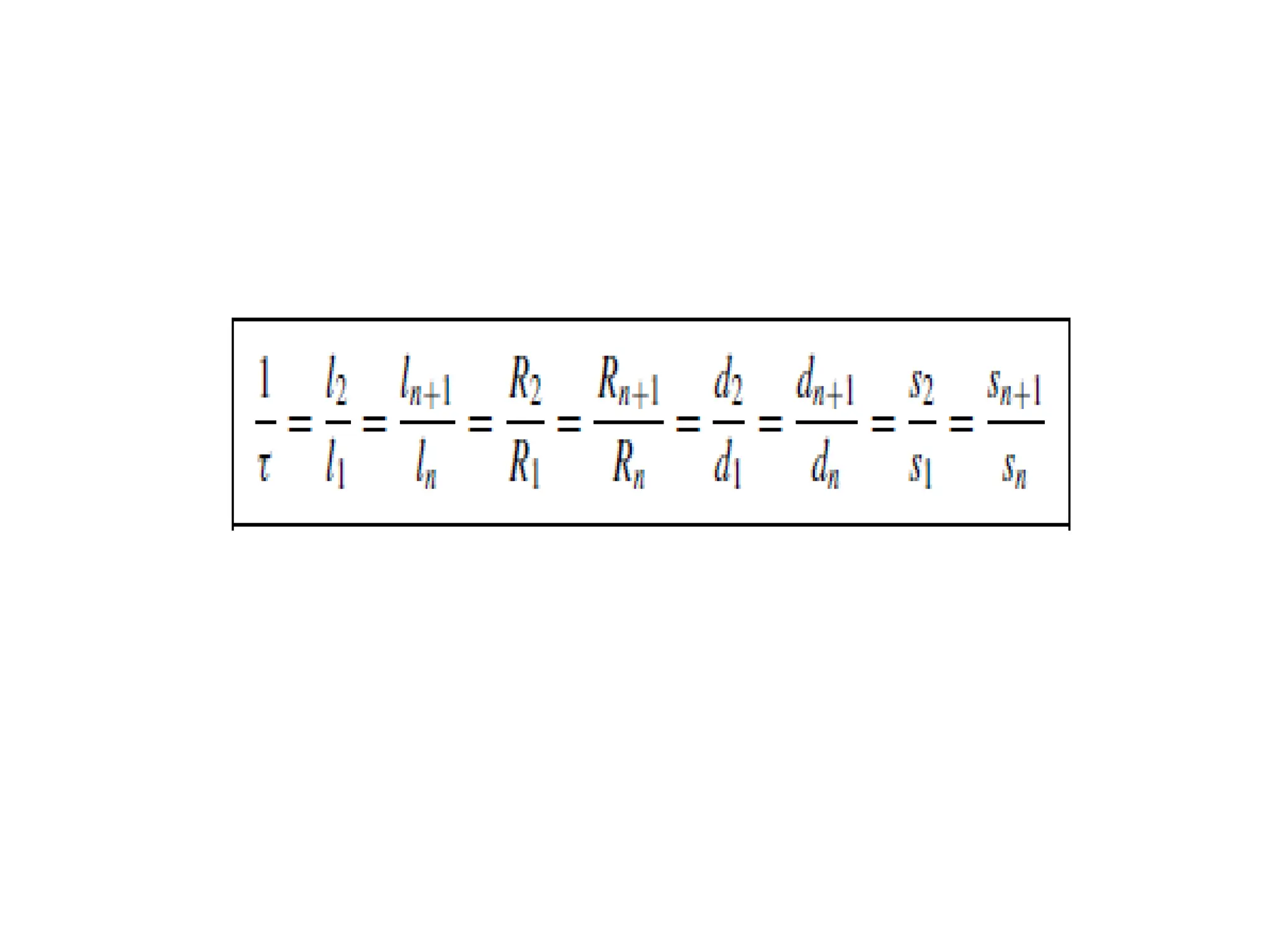
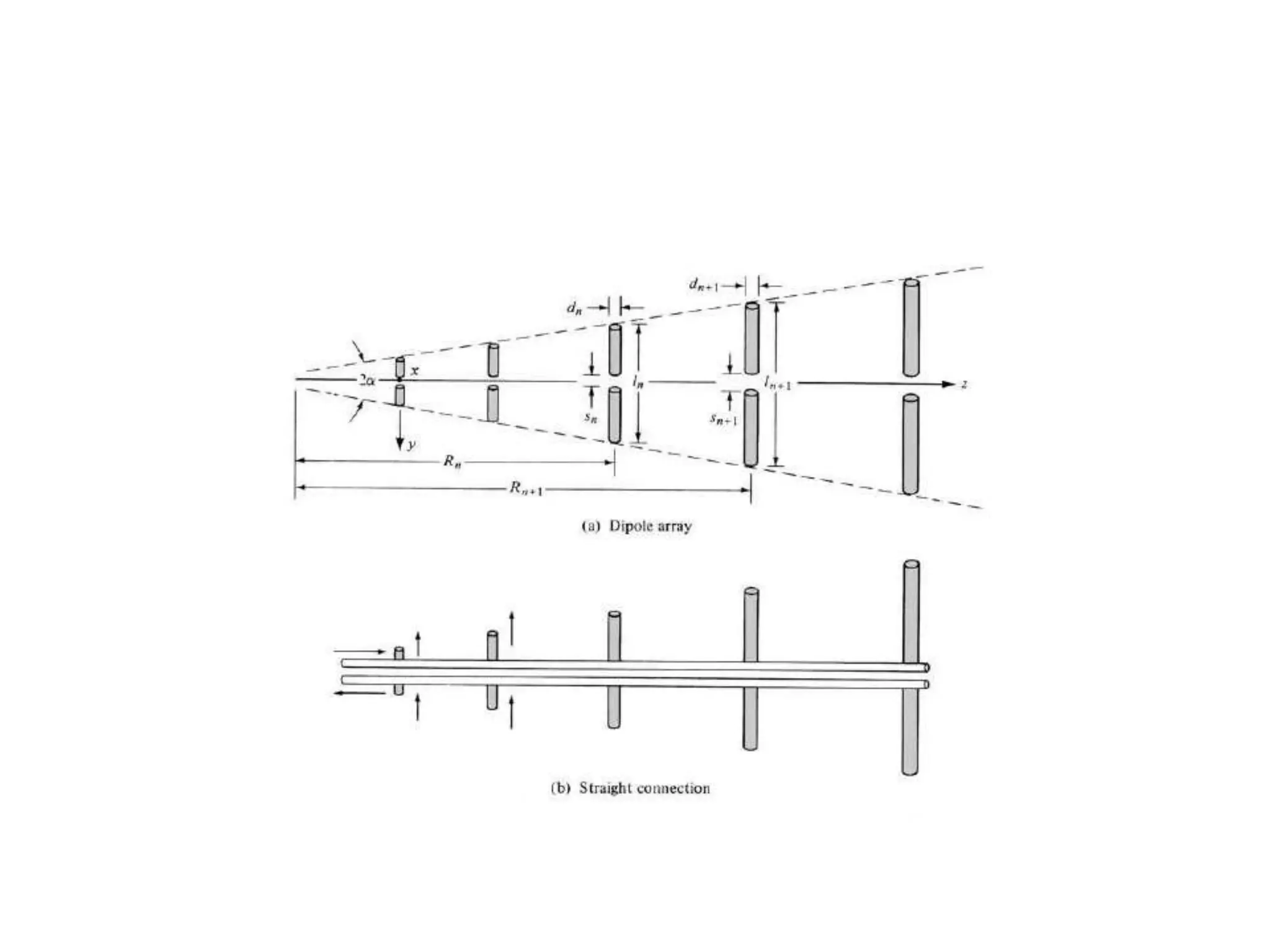
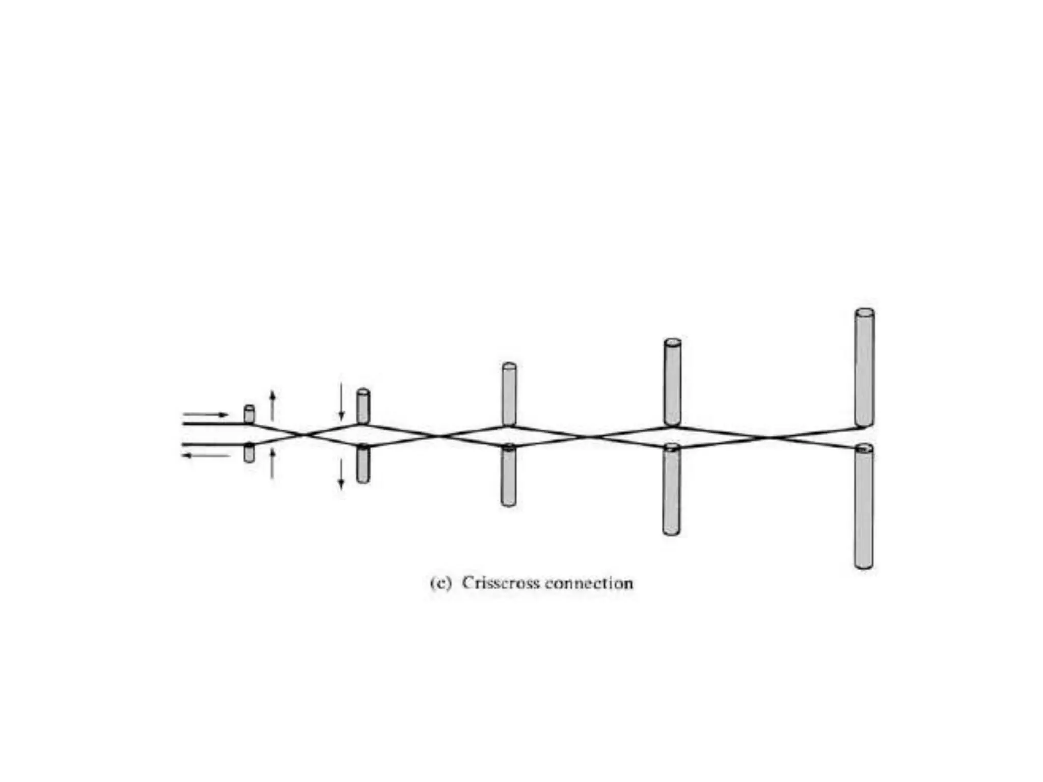
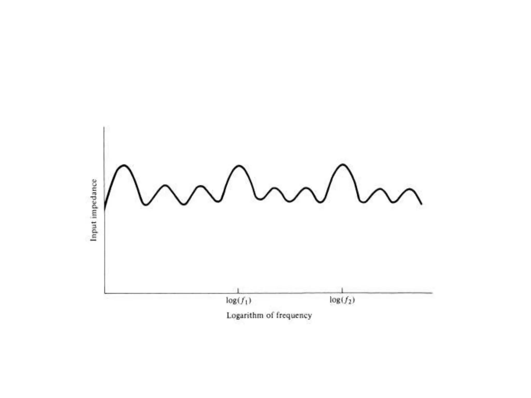
• It consists of a sequence of
• side-by-side parallel linear dipoles forming a
coplanar array. Although this antenna has
• slightly smaller directivities thanthe Yagi–Uda
array (7-12 dB), they are achievable
• and maintained over much wider bandwidths.
• While the geometrical dimensions of the Yagi–
Uda array elements do not follow
• any set pattern, the lengths (ln’s), spacings
(Rn’s), diameters (dn’s), and even gap
• spacings at dipole centers (sn’s) of the log-
periodic array increase logarithmically as
• defined by the inverse of the geometric ratio
τ. That is,
• Another parameter that is usually associated with a log-periodic dipole
array is the
• spacing factor σ defined by
• Straight lines through the dipole ends meet to form an angle 2α which is a
characteristic of frequency independent structures.
• Because it is usually very difficult to obtain wires or tubing of many
different diameters and to maintain tolerances of very small gap spacings,
constant dimensions in these
• can be used.
• These relatively minor factors will not sufficiently degrade the overall
performance.
• While only one element of the Yagi–Uda array
is directly energized by the feed
• line, while the others operate in a parasitic
mode, all the elements of the log-periodic
• array are connected.
• It was recognized that by mechanically crisscrossing or
transposing the feed between
• adjacent elements a 180◦ phase is added to the
terminal
• of each element. The mechanical phase reversal
between these elements produces a phase progression
• so that the energy is beamed end fire in the direction
of the shorter elements. The
• most active elements for this feed arrangement are
those that are near resonant with a
• combined radiation pattern toward the vertex of the
array.
• The cutoff frequencies of the truncated
structure can be determined by the electrical
• lengths of the longest and shortest elements
of the structure. The lower cutoff
• frequency occurs approximately when the
longest element is λ/2; however, the high
• cutoff frequency occurs when the shortest
element is nearly λ/2 only when the active
• region is very narrow. Usually it extends
beyond that element. The active region of
• the log-periodic dipole array is near the
elements whose lengths are nearly or slightly
• smaller than λ/2. The role of active elements
is passed from the longer to the shorter
• elements as the frequency increases.
• If the input impedance of a log-periodic antenna is
plotted as a function of the logarithm of the
• frequency, it will be periodic (not necessarily
sinusoidal) with each cycle being exactly
• identical to the preceding one. Hence the name log-
periodic, because the variations are periodic with
respect to the logarithm of the frequency. A typical
variation of the
• impedance as a function of frequency is shown in
Figure 11.11. Other parameters that
• undergo similar variations are the pattern, directivity,
beamwidth, and side lobe level.
Log Periodic Dipole Array Log Periodic Dipole Array.pptx

Log Periodic Dipole Array Log Periodic Dipole Array.pptx

  • 2.
    • It consistsof a sequence of • side-by-side parallel linear dipoles forming a coplanar array. Although this antenna has • slightly smaller directivities thanthe Yagi–Uda array (7-12 dB), they are achievable • and maintained over much wider bandwidths.
  • 3.
    • While thegeometrical dimensions of the Yagi– Uda array elements do not follow • any set pattern, the lengths (ln’s), spacings (Rn’s), diameters (dn’s), and even gap • spacings at dipole centers (sn’s) of the log- periodic array increase logarithmically as • defined by the inverse of the geometric ratio τ. That is,
  • 7.
    • Another parameterthat is usually associated with a log-periodic dipole array is the • spacing factor σ defined by • Straight lines through the dipole ends meet to form an angle 2α which is a characteristic of frequency independent structures. • Because it is usually very difficult to obtain wires or tubing of many different diameters and to maintain tolerances of very small gap spacings, constant dimensions in these • can be used. • These relatively minor factors will not sufficiently degrade the overall performance.
  • 8.
    • While onlyone element of the Yagi–Uda array is directly energized by the feed • line, while the others operate in a parasitic mode, all the elements of the log-periodic • array are connected.
  • 9.
    • It wasrecognized that by mechanically crisscrossing or transposing the feed between • adjacent elements a 180◦ phase is added to the terminal • of each element. The mechanical phase reversal between these elements produces a phase progression • so that the energy is beamed end fire in the direction of the shorter elements. The • most active elements for this feed arrangement are those that are near resonant with a • combined radiation pattern toward the vertex of the array.
  • 10.
    • The cutofffrequencies of the truncated structure can be determined by the electrical • lengths of the longest and shortest elements of the structure. The lower cutoff • frequency occurs approximately when the longest element is λ/2; however, the high • cutoff frequency occurs when the shortest element is nearly λ/2 only when the active
  • 11.
    • region isvery narrow. Usually it extends beyond that element. The active region of • the log-periodic dipole array is near the elements whose lengths are nearly or slightly • smaller than λ/2. The role of active elements is passed from the longer to the shorter • elements as the frequency increases.
  • 12.
    • If theinput impedance of a log-periodic antenna is plotted as a function of the logarithm of the • frequency, it will be periodic (not necessarily sinusoidal) with each cycle being exactly • identical to the preceding one. Hence the name log- periodic, because the variations are periodic with respect to the logarithm of the frequency. A typical variation of the • impedance as a function of frequency is shown in Figure 11.11. Other parameters that • undergo similar variations are the pattern, directivity, beamwidth, and side lobe level.