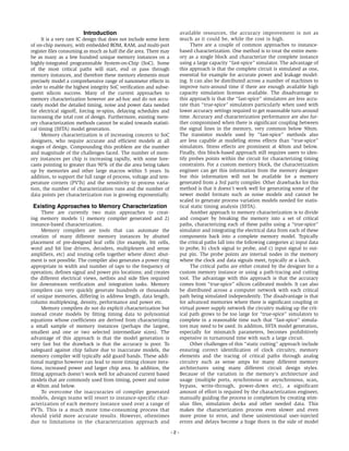
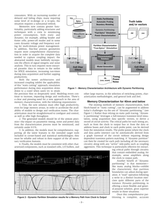
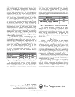
SlideShare a Scribd company logo
1 of 4
Download to read offline
High-Performance, High-Precision Memory Characterization
Technical White Paper
Federico Politi, Altos Design Automation, Inc.
High-Performance, High-Precision Memory Characterization
Introduction
It is a very rare IC design that does not include some form
of on-chip memory, with embedded ROM, RAM, and multi-port
register files consuming as much as half the die area. There may
be as many as a few hundred unique memory instances on a
highly-integrated programmable System-on-Chip (SoC). Some
of the most critical paths will start, end or pass through
memory instances, and therefore these memory elements must
precisely model a comprehensive range of nanometer effects in
order to enable the highest integrity SoC verification and subse-
quent silicon success. Many of the current approaches to
memory characterization however are ad-hoc and do not accu-
rately model the detailed timing, noise and power data needed
for electrical signoff, forcing re-spins, delaying schedules and
increasing the total cost of design. Furthermore, existing mem-
ory characterization methods cannot be scaled towards statisti-
cal timing (SSTA) model generation.
Memory characterization is of increasing concern to SoC
designers, who require accurate and efficient models at all
stages of design. Compounding this problem are the number
and magnitude of the challenges faced. The number of mem-
ory instances per chip is increasing rapidly, with some fore-
casts pointing to greater than 90% of the die area being taken
up by memories and other large macros within 5 years. In
addition, to support the full range of process, voltage and tem-
perature corners (PVTs) and the sensitivity to process varia-
tion, the number of characterization runs and the number of
data points per characterization run is growing exponentially.
Existing Approaches to Memory Characterization
There are currently two main approaches to creat-
ing memory models 1) memory compiler generated and 2)
instance-based characterization.
Memory compilers are tools that can automate the
creation of many different memory instances by abutted
placement of pre-designed leaf cells (for example, bit cells,
word and bit line drivers, decoders, multiplexers and sense
amplifiers, etc) and routing cells together where direct abut-
ment is not possible. The compiler also generates a power ring
appropriate in width and number of taps to the frequency of
operation; defines signal and power pin locations; and creates
the different electrical views, netlists and side files required
for downstream verification and integration tasks. Memory
compilers can very quickly generate hundreds or thousands
of unique memories, differing in address length, data length,
column multiplexing, density, performance and power etc.
Memory compilers do not do explicit characterization but
instead create models by fitting timing data to polynomial
equations whose coefficients are derived from characterizing
a small sample of memory instances (perhaps the largest,
smallest and one or two selected intermediate sizes). The
advantage of this approach is that the model generation is
very fast but the drawback is that the accuracy is poor. To
safeguard against chip failure due to inaccurate models, the
memory compiler will typically add guard bands. These addi-
tional margins however can lead to more timing closure itera-
tions, increased power and larger chip area. In addition, the
fitting approach doesn’t work well for advanced current based
models that are commonly used from timing, power and noise
at 40nm and below.
To overcome the inaccuracies of compiler generated
models, design teams will resort to instance-specific char-
acterization of each memory instance used over a range of
PVTs. This is a much more time-consuming process that
should yield more accurate results. However, oftentimes
due to limitations in the characterization approach and
available resources, the accuracy improvement is not as
much as it could be, while the cost is high.
There are a couple of common approaches to instance-
based characterization. One method is to treat the entire mem-
ory as a single block and characterize the complete instance
using a large capacity “fast-spice” simulator. The advantage of
this approach is that the complete circuit is simulated as one,
essential for example for accurate power and leakage model-
ing. It can also be distributed across a number of machines to
improve turn-around time if there are enough available high
capacity simulation licenses available. The disadvantage to
this approach is that the “fast-spice” simulators are less accu-
rate than “true-spice” simulators particularly when used with
lower accuracy settings required to get reasonable turn-around
time. Accuracy and characterization performance are also fur-
ther compromised when there is significant coupling between
the signal lines in the memory, very common below 90nm.
The transistor models used by “fast-spice” methods also
are less capable at modeling stress effects than “true-spice”
simulators. Stress effects are prominent at 40nm and below.
Finally, this block-based approach still requires users to iden-
tify probes points within the circuit for characterizing timing
constraints. For a custom memory block, the characterization
engineer can get this information from the memory designer
but this information will not be available for a memory
generated from a 3rd party compiler. Other drawbacks for this
method is that it doesn’t work well for generating some of the
newer model formats such as noise models and cannot be
scaled to generate process variation models needed for statis-
tical static timing analysis (SSTA).
Another approach to memory characterization is to divide
and conquer by breaking the memory into a set of critical
paths, characterizing each of these paths using a “true-spice”
simulator and integrating the electrical data from each of these
components back into a complete memory model. Typically
the critical paths fall into the following categories a) input data
to probe, b) clock signal to probe, and c) input signal to out-
put pin. The probe points are internal nodes in the memory
where the clock and data signals meet, typically at a latch.
The critical paths are either created by the designer for a
custom memory instance or using a path-tracing and cutting
tool. The advantage with this approach is that the accuracy
comes from “true-spice” silicon calibrated models. It can also
be distributed across a computer network with each critical
path being simulated independently. The disadvantage is that
for advanced memories where there is significant coupling or
virtual power supply network the circuitry making up the crit-
ical path grows to be too large for “true-spice” simulators to
complete in a reasonable time such that “fast-spice” simula-
tors may need to be used. In addition, SSTA model generation,
especially for mismatch parameters, becomes prohibitively
expensive in turnaround time with such a large circuit.
Other challenges of this “static cutting” approach include
ensuring correct identification of clock circuitry, memory
elements and the tracing of critical paths through analog
circuitry such as sense amps for many different memory
architectures using many different circuit design styles.
Because of the variation in the memory's architecture and
usage (multiple ports, synchronous or asynchronous, scan,
bypass, write-through, power-down etc), a significant
amount of effort is required by the characterization engineer,
manually guiding the process to completion by creating stim-
ulus files, simulation decks and other needed data. This
makes the characterization process even slower and even
more prone to error, and these unintentional user-injected
errors and delays become a huge thorn in the side of model
- 2 -
consumers. With an increasing number of
delayed and failing chips, many requiring
some level of re-design or a re-spin, the
situation requires a substantial rethink.
Memories now contain greater func-
tionality, particularly adding structures and
techniques with a view to minimizing
power consumption, both static and
dynamic; for example, adding header and
footer cells, power-off modes and in some
cases dynamic voltage and frequency scal-
ing for multi-domain power management.
In addition, fine-line process geometries
require more comprehensive characteriza-
tion in order to acquire the complete data
needed to capture coupling impact; the
abstracted models must faithfully incorpo-
rate the effects of signal integrity and noise
analysis. This in turn requires more extract-
ed parasitic data to remain in the netlist
for SPICE simulation, increasing run-times
during data acquisition and further sapping
productivity.
Both the newer architectures and
increased coupling inhibit the applicability
of this “static cutting” approach; simulation
performance during data acquisition slows
down to a crawl when users try to retain
the precision they so desperately need. Modeling errors con-
tinue to increase, impacting design and verification. There's
a clear and pressing need for a new approach in the area of
memory characterization, with the following requirements:
1. First, the new solution must offer high productivity,
even for large memory arrays, in order to accelerate the avail-
ability of models to design and verification teams. The char-
acterization must be straightforward to configure and control,
as well as offer high throughput.
2. The generated models should be of the utmost preci-
sion—the impact on parametric timing, noise and power data
from the characterization process must be minimized, and
certainly under 0.5%.
3. In addition, the models must be comprehensive, sup-
porting all the latest features in the intended target tools
included in corner-based and statistical methodologies; they
must be reliable and robust in their support of the all neces-
sary verification features.
4. Finally, the models must be consistent with other char-
acterized components, such as standard cells, I/O buffers, and
other large macros, in the selection of switching points, char-
acterization methodologies, and general look and feel.
Memory Characterization for 40nm and below
The existing methods of memory characterization, both
block-based or “static cutting”, can be augmented to address
today’s challenges via the use of “dynamic partitioning.” (see
Figure 1.) Rather than relying on static path tracing, “dynam-
ic partitioning” leverages a full-instance transistor-level simu-
lation, using acquisition data specific vectors, to derive a
record of circuit activity. The critical paths for each timing arc,
such as from the clock to output bus or from the data or
address buses and clock to each probe point, can be derived
from the simulation results. The probe points where the clock
and data paths intersect can be automatically derived from
a graph traversal of the circuit without requiring design
dependent transistor pattern matching. A “dynamic partition”
can then be created for each path including all the necessary
circuitry along with any “active” side-paths such as coupling
aggressors. This technique is particularly effective for extract-
ing critical paths through circuitry
that contain embedded analog; for
example, sense amplifiers along
the clock to output path.
Another benefit of “dynamic
partitioning” is that memories—
like many analog blocks—exhibit
the characteristic that partition
boundaries can adjust during oper-
ation. A ”read” operation following
a write to a distinct location exer-
cises quite different parts of the
instance. Dynamic partitioning, in
offering a more flexible and gener-
al purpose solution, gives superior
results in these situations.
Once this comprehensive par-
titioning is complete, accurate
- 3 -
TCL
Spice
netlist(s)
.tbl .vec
.lib
(ccs, ecsm)
Model Generation
Automatic Probing
Boundary Modeling
“Fast-Spice” Simulation
Power Characterization
Characterization
Database
Waveform
db
Cell Char
Cell Char
Client
Cell Char
Client
Cell Char
Cell Char
Cell Char
Partition Characterization
“True-Spice” Simulation
Static Partitioning
Dynamic Partitioning
Timing
Power
Noise
Truth table
and/or vectors
Figure 1 - Memory Characterization Architecture with Dynamic Partitioning
Figure 2 - Dynamic Partition Simulation results for a Memory Path from Clock to Output
block-based memory characterization approach with “fast-
spice” versus using dynamic partitioning with “true-spice.”
For the more complex dual port RAM, the run-time improve-
ment is over 60X. This differential grows with the size of the
memory as the runtime for the simulations of dynamic parti-
tions remains constant unlike the block-based runtime which
grows super linearly.
Memory Type Speedup
288 Kb single port SRAM 10.4X
36Kb dual port, dual clock SRAM with 67.7X
scan, bypass
Figure 4 - Speed Improvement from Dynamic Partitioning
The “dynamic partitioning” approach can be quickly
deployed either for instance-based characterization of inte-
grated into a memory compiler. The additional information
required is minor; either stimulus or functional truth-tables
derived from the memory datasheet. It is applicable to all
flavors of embedded memory such as SRAM, ROM, CAM and
registers files and also for custom macro blocks such as
SERDES and PHY.
Conclusion
Applying “dynamic partitioning” to large memory
instances eliminates the errors seen in solutions that employ
only static SPICE netlist-cutting or rely totally on “fast-spice”
simulators. This new technology provides the most precise
and comprehensive models for design, verification and analy-
sis available today while enabling very fast runtimes , often
an order of magnitude faster for large macros. This superior
level of precision enables designers to be much more selective
in the application of timing margins during design and verifi-
cation resulting in higher performance designs, optimal die
area, and closer correlation with manufactured silicon.
When coupled to a proven cell characterization platform,
a consistent characterization methodology can be used for
cells and macros, critical for electrical sign-off and analysis of
large and complex SoC designs.
Effective and efficient characterization certainly helps get
models promptly into the hands of designers and into the
flow, but precision and accuracy are everything. Utilizing
“dynamic partitioning” designers can benefit from the com-
prehensive, accurate and efficient models it generates, with
time-to-market and die-size improvements the result.
© 2009 Altos Design Automation. All rights reserved.
Altos Design Automation
4020 Moorpark Avenue, Suite 100, San Jose, CA 95117
Phone 408.980.8056 • Fax 408.557.0637
Email info@altos-da.com • www.altos-da.com
- 4 -
SPICE simulations are performed independently on decom-
posed partitions, with the assembled results faithfully repre-
senting the timing behavior of the original, larger instance.
This “bi-modal view” uses the full-instance simulation to
determine large-scale characteristics, like power and partition
connectivity, while the much smaller individual partitions,
each containing typically only a few hundred transistors, are
simulated using a “true-spice” simulator to ensure the highest
levels of precision. Communication between the full-block
and partitioned sub-block simulations ensures identical initial
conditions and DC solutions, essential for obtaining precise
and consistent data. This analysis and partitioning technology
can be coupled to sophisticated job control for parallel exe-
cution and distribution across the network. In addition, the
partitions can be represented as super-cells to cell characteri-
zation systems to: enable the generation of current sources
models (CCS and ECSM) for timing, noise and power analysis;
and even the generation of statistical timing models using the
same proven statistical characterization methods for standard
cells. Consistent application of a library-wide characterization
approach ensures interoperability between all instances in the
design, serving to eliminate hard to find timing errors due to
library element incompatibilities.
As each “dynamic partition” is simulated using “true-
spice,” the generated timing models are nearly identical to
simulating the complete block using “true-spice” which is
impractical for all but the smallest memory instances. The
only source of error is related to tying off in-active gates and
wires. The table in Figure 3 shows a comparison between a
golden result (small memory simulated entirely in “true-
spice”), the results from dynamic partitioning and the result
from simulating the entire block in “fast-spice.” The accuracy
loss due to “dynamic partitioning” is less than 1% for delay,
transition and constraints while using “fast-spice” results in
up to 6% difference.
Accuracy Vs “true-spice” Delay Transition Constraints
“fast-spice” 5.98% 3.17% 2.61%
Dynamic partitioning 0.82% 0.41% 0.50%
Figure 3 – Accuracy of Dynamic partitioning Vs “true-spice”
As well as delivering accuracy, dynamic partitioning
greatly improves both the CPU time and total turn-around
time for memory characterization by an order of magnitude or
more. Figure 4 shows the total CPU time comparison using a

More Related Content

Viewers also liked

NICHOLASKINGResume091315
NICHOLASKINGResume091315NICHOLASKINGResume091315
NICHOLASKINGResume091315Nicholas King
 
SRAM redundancy insertion
SRAM redundancy insertionSRAM redundancy insertion
SRAM redundancy insertionchiportal
 
Average and Static Power Analysis of a 6T and 7T SRAM Bit-Cell at 180nm, 90nm...
Average and Static Power Analysis of a 6T and 7T SRAM Bit-Cell at 180nm, 90nm...Average and Static Power Analysis of a 6T and 7T SRAM Bit-Cell at 180nm, 90nm...
Average and Static Power Analysis of a 6T and 7T SRAM Bit-Cell at 180nm, 90nm...idescitation
 
Design of a low power asynchronous SRAM in 45nM CMOS
Design of a low power asynchronous SRAM in 45nM CMOSDesign of a low power asynchronous SRAM in 45nM CMOS
Design of a low power asynchronous SRAM in 45nM CMOSNirav Desai
 
slides_tese_v3_paraAnexoTesis
slides_tese_v3_paraAnexoTesisslides_tese_v3_paraAnexoTesis
slides_tese_v3_paraAnexoTesisJorge Tonfat
 
Bandpass Filter in S-Band by D.C.Vaghela,LJIET,Ahmedabad,Gujarat.
Bandpass Filter in S-Band by D.C.Vaghela,LJIET,Ahmedabad,Gujarat.Bandpass Filter in S-Band by D.C.Vaghela,LJIET,Ahmedabad,Gujarat.
Bandpass Filter in S-Band by D.C.Vaghela,LJIET,Ahmedabad,Gujarat.Dipak Vaghela
 
SRAM read and write and sense amplifier
SRAM read and write and sense amplifierSRAM read and write and sense amplifier
SRAM read and write and sense amplifierSoumyajit Langal
 
Sram memory design
Sram memory designSram memory design
Sram memory designNIT Goa
 
Hardware Memory
Hardware MemoryHardware Memory
Hardware MemoryVinit Vyas
 
Write stability analysis of 8 t novel sram cell
Write stability analysis of 8 t novel sram cellWrite stability analysis of 8 t novel sram cell
Write stability analysis of 8 t novel sram cellMr Santosh Kumar Chhotray
 
Reliability and yield
Reliability and yield Reliability and yield
Reliability and yield rohitladdu
 
Buy SRAM
Buy SRAM Buy SRAM
Buy SRAM Rabyte
 
Totem Technologies for Analog, Memory, Mixed-Signal Designs
Totem Technologies for Analog, Memory, Mixed-Signal DesignsTotem Technologies for Analog, Memory, Mixed-Signal Designs
Totem Technologies for Analog, Memory, Mixed-Signal DesignsAnsys
 

Viewers also liked (20)

NICHOLASKINGResume091315
NICHOLASKINGResume091315NICHOLASKINGResume091315
NICHOLASKINGResume091315
 
mohit resume
mohit resumemohit resume
mohit resume
 
SRAM redundancy insertion
SRAM redundancy insertionSRAM redundancy insertion
SRAM redundancy insertion
 
Average and Static Power Analysis of a 6T and 7T SRAM Bit-Cell at 180nm, 90nm...
Average and Static Power Analysis of a 6T and 7T SRAM Bit-Cell at 180nm, 90nm...Average and Static Power Analysis of a 6T and 7T SRAM Bit-Cell at 180nm, 90nm...
Average and Static Power Analysis of a 6T and 7T SRAM Bit-Cell at 180nm, 90nm...
 
Resume.
Resume.Resume.
Resume.
 
64 bit sram memory: design paper
64 bit sram memory: design paper64 bit sram memory: design paper
64 bit sram memory: design paper
 
Design of a low power asynchronous SRAM in 45nM CMOS
Design of a low power asynchronous SRAM in 45nM CMOSDesign of a low power asynchronous SRAM in 45nM CMOS
Design of a low power asynchronous SRAM in 45nM CMOS
 
slides_tese_v3_paraAnexoTesis
slides_tese_v3_paraAnexoTesisslides_tese_v3_paraAnexoTesis
slides_tese_v3_paraAnexoTesis
 
Bandpass Filter in S-Band by D.C.Vaghela,LJIET,Ahmedabad,Gujarat.
Bandpass Filter in S-Band by D.C.Vaghela,LJIET,Ahmedabad,Gujarat.Bandpass Filter in S-Band by D.C.Vaghela,LJIET,Ahmedabad,Gujarat.
Bandpass Filter in S-Band by D.C.Vaghela,LJIET,Ahmedabad,Gujarat.
 
SRAM read and write and sense amplifier
SRAM read and write and sense amplifierSRAM read and write and sense amplifier
SRAM read and write and sense amplifier
 
Sram memory design
Sram memory designSram memory design
Sram memory design
 
Lecture14
Lecture14Lecture14
Lecture14
 
Hardware Memory
Hardware MemoryHardware Memory
Hardware Memory
 
Write stability analysis of 8 t novel sram cell
Write stability analysis of 8 t novel sram cellWrite stability analysis of 8 t novel sram cell
Write stability analysis of 8 t novel sram cell
 
SRAM
SRAMSRAM
SRAM
 
Reliability and yield
Reliability and yield Reliability and yield
Reliability and yield
 
SRAM
SRAMSRAM
SRAM
 
Buy SRAM
Buy SRAM Buy SRAM
Buy SRAM
 
Totem Technologies for Analog, Memory, Mixed-Signal Designs
Totem Technologies for Analog, Memory, Mixed-Signal DesignsTotem Technologies for Analog, Memory, Mixed-Signal Designs
Totem Technologies for Analog, Memory, Mixed-Signal Designs
 
SRAM Design
SRAM DesignSRAM Design
SRAM Design
 

Similar to LiberateMXWhitePaper

Robust Fault Tolerance in Content Addressable Memory Interface
Robust Fault Tolerance in Content Addressable Memory InterfaceRobust Fault Tolerance in Content Addressable Memory Interface
Robust Fault Tolerance in Content Addressable Memory InterfaceIOSRJVSP
 
Trends and challenges in IP based SOC design
Trends and challenges in IP based SOC designTrends and challenges in IP based SOC design
Trends and challenges in IP based SOC designAishwaryaRavishankar8
 
Low power network on chip architectures: A survey
Low power network on chip architectures: A surveyLow power network on chip architectures: A survey
Low power network on chip architectures: A surveyCSITiaesprime
 
IRJET- Reduction of Dark Silicon through Efficient Power Reduction Designing ...
IRJET- Reduction of Dark Silicon through Efficient Power Reduction Designing ...IRJET- Reduction of Dark Silicon through Efficient Power Reduction Designing ...
IRJET- Reduction of Dark Silicon through Efficient Power Reduction Designing ...IRJET Journal
 
Michael Gschwind, Cell Broadband Engine: Exploiting multiple levels of parall...
Michael Gschwind, Cell Broadband Engine: Exploiting multiple levels of parall...Michael Gschwind, Cell Broadband Engine: Exploiting multiple levels of parall...
Michael Gschwind, Cell Broadband Engine: Exploiting multiple levels of parall...Michael Gschwind
 
Investigations on Implementation of Ternary Content Addressable Memory Archit...
Investigations on Implementation of Ternary Content Addressable Memory Archit...Investigations on Implementation of Ternary Content Addressable Memory Archit...
Investigations on Implementation of Ternary Content Addressable Memory Archit...IRJET Journal
 
Webinar on Latency and throughput computation of automotive EE network
Webinar on Latency and throughput computation of automotive EE networkWebinar on Latency and throughput computation of automotive EE network
Webinar on Latency and throughput computation of automotive EE networkDeepak Shankar
 
IEEE Emerging topic in computing Title and Abstract 2016
IEEE Emerging topic in computing Title and Abstract 2016 IEEE Emerging topic in computing Title and Abstract 2016
IEEE Emerging topic in computing Title and Abstract 2016 tsysglobalsolutions
 
Vlsi 2015 2016 ieee project list-(v)_with abstract
Vlsi 2015 2016 ieee project list-(v)_with abstractVlsi 2015 2016 ieee project list-(v)_with abstract
Vlsi 2015 2016 ieee project list-(v)_with abstractS3 Infotech IEEE Projects
 
SRAM BASED IN-MEMORY MATRIX VECTOR MULTIPLIER
SRAM BASED IN-MEMORY MATRIX VECTOR MULTIPLIERSRAM BASED IN-MEMORY MATRIX VECTOR MULTIPLIER
SRAM BASED IN-MEMORY MATRIX VECTOR MULTIPLIERIRJET Journal
 
Automated clock mesh analysis for faster turnaround
Automated clock mesh analysis for faster turnaroundAutomated clock mesh analysis for faster turnaround
Automated clock mesh analysis for faster turnaroundAnimesh Sharma
 
STUDY OF VARIOUS FACTORS AFFECTING PERFORMANCE OF MULTI-CORE PROCESSORS
STUDY OF VARIOUS FACTORS AFFECTING PERFORMANCE OF MULTI-CORE PROCESSORSSTUDY OF VARIOUS FACTORS AFFECTING PERFORMANCE OF MULTI-CORE PROCESSORS
STUDY OF VARIOUS FACTORS AFFECTING PERFORMANCE OF MULTI-CORE PROCESSORSijdpsjournal
 
Ijiret archana-kv-increasing-memory-performance-using-cache-optimizations-in-...
Ijiret archana-kv-increasing-memory-performance-using-cache-optimizations-in-...Ijiret archana-kv-increasing-memory-performance-using-cache-optimizations-in-...
Ijiret archana-kv-increasing-memory-performance-using-cache-optimizations-in-...IJIR JOURNALS IJIRUSA
 
Webinar: Detecting Deadlocks in Electronic Systems using Time-based Simulation
Webinar: Detecting Deadlocks in Electronic Systems using Time-based SimulationWebinar: Detecting Deadlocks in Electronic Systems using Time-based Simulation
Webinar: Detecting Deadlocks in Electronic Systems using Time-based SimulationDeepak Shankar
 
IRJET-A Review on Trends in Multicore Processor Based on Cache and Power Diss...
IRJET-A Review on Trends in Multicore Processor Based on Cache and Power Diss...IRJET-A Review on Trends in Multicore Processor Based on Cache and Power Diss...
IRJET-A Review on Trends in Multicore Processor Based on Cache and Power Diss...IRJET Journal
 
week_2Lec02_CS422.pptx
week_2Lec02_CS422.pptxweek_2Lec02_CS422.pptx
week_2Lec02_CS422.pptxmivomi1
 

Similar to LiberateMXWhitePaper (20)

Robust Fault Tolerance in Content Addressable Memory Interface
Robust Fault Tolerance in Content Addressable Memory InterfaceRobust Fault Tolerance in Content Addressable Memory Interface
Robust Fault Tolerance in Content Addressable Memory Interface
 
eet_NPU_file.PDF
eet_NPU_file.PDFeet_NPU_file.PDF
eet_NPU_file.PDF
 
Trends and challenges in IP based SOC design
Trends and challenges in IP based SOC designTrends and challenges in IP based SOC design
Trends and challenges in IP based SOC design
 
Low power network on chip architectures: A survey
Low power network on chip architectures: A surveyLow power network on chip architectures: A survey
Low power network on chip architectures: A survey
 
IRJET- Reduction of Dark Silicon through Efficient Power Reduction Designing ...
IRJET- Reduction of Dark Silicon through Efficient Power Reduction Designing ...IRJET- Reduction of Dark Silicon through Efficient Power Reduction Designing ...
IRJET- Reduction of Dark Silicon through Efficient Power Reduction Designing ...
 
Michael Gschwind, Cell Broadband Engine: Exploiting multiple levels of parall...
Michael Gschwind, Cell Broadband Engine: Exploiting multiple levels of parall...Michael Gschwind, Cell Broadband Engine: Exploiting multiple levels of parall...
Michael Gschwind, Cell Broadband Engine: Exploiting multiple levels of parall...
 
Investigations on Implementation of Ternary Content Addressable Memory Archit...
Investigations on Implementation of Ternary Content Addressable Memory Archit...Investigations on Implementation of Ternary Content Addressable Memory Archit...
Investigations on Implementation of Ternary Content Addressable Memory Archit...
 
Conference 2 ieee
Conference 2 ieeeConference 2 ieee
Conference 2 ieee
 
Webinar on Latency and throughput computation of automotive EE network
Webinar on Latency and throughput computation of automotive EE networkWebinar on Latency and throughput computation of automotive EE network
Webinar on Latency and throughput computation of automotive EE network
 
IEEE Emerging topic in computing Title and Abstract 2016
IEEE Emerging topic in computing Title and Abstract 2016 IEEE Emerging topic in computing Title and Abstract 2016
IEEE Emerging topic in computing Title and Abstract 2016
 
G1034853
G1034853G1034853
G1034853
 
Vlsi 2015 2016 ieee project list-(v)_with abstract
Vlsi 2015 2016 ieee project list-(v)_with abstractVlsi 2015 2016 ieee project list-(v)_with abstract
Vlsi 2015 2016 ieee project list-(v)_with abstract
 
SRAM BASED IN-MEMORY MATRIX VECTOR MULTIPLIER
SRAM BASED IN-MEMORY MATRIX VECTOR MULTIPLIERSRAM BASED IN-MEMORY MATRIX VECTOR MULTIPLIER
SRAM BASED IN-MEMORY MATRIX VECTOR MULTIPLIER
 
Automated clock mesh analysis for faster turnaround
Automated clock mesh analysis for faster turnaroundAutomated clock mesh analysis for faster turnaround
Automated clock mesh analysis for faster turnaround
 
STUDY OF VARIOUS FACTORS AFFECTING PERFORMANCE OF MULTI-CORE PROCESSORS
STUDY OF VARIOUS FACTORS AFFECTING PERFORMANCE OF MULTI-CORE PROCESSORSSTUDY OF VARIOUS FACTORS AFFECTING PERFORMANCE OF MULTI-CORE PROCESSORS
STUDY OF VARIOUS FACTORS AFFECTING PERFORMANCE OF MULTI-CORE PROCESSORS
 
Ijiret archana-kv-increasing-memory-performance-using-cache-optimizations-in-...
Ijiret archana-kv-increasing-memory-performance-using-cache-optimizations-in-...Ijiret archana-kv-increasing-memory-performance-using-cache-optimizations-in-...
Ijiret archana-kv-increasing-memory-performance-using-cache-optimizations-in-...
 
Priorities Shift In IC Design
Priorities Shift In IC DesignPriorities Shift In IC Design
Priorities Shift In IC Design
 
Webinar: Detecting Deadlocks in Electronic Systems using Time-based Simulation
Webinar: Detecting Deadlocks in Electronic Systems using Time-based SimulationWebinar: Detecting Deadlocks in Electronic Systems using Time-based Simulation
Webinar: Detecting Deadlocks in Electronic Systems using Time-based Simulation
 
IRJET-A Review on Trends in Multicore Processor Based on Cache and Power Diss...
IRJET-A Review on Trends in Multicore Processor Based on Cache and Power Diss...IRJET-A Review on Trends in Multicore Processor Based on Cache and Power Diss...
IRJET-A Review on Trends in Multicore Processor Based on Cache and Power Diss...
 
week_2Lec02_CS422.pptx
week_2Lec02_CS422.pptxweek_2Lec02_CS422.pptx
week_2Lec02_CS422.pptx
 

LiberateMXWhitePaper

  • 1. High-Performance, High-Precision Memory Characterization Technical White Paper Federico Politi, Altos Design Automation, Inc. High-Performance, High-Precision Memory Characterization
  • 2. Introduction It is a very rare IC design that does not include some form of on-chip memory, with embedded ROM, RAM, and multi-port register files consuming as much as half the die area. There may be as many as a few hundred unique memory instances on a highly-integrated programmable System-on-Chip (SoC). Some of the most critical paths will start, end or pass through memory instances, and therefore these memory elements must precisely model a comprehensive range of nanometer effects in order to enable the highest integrity SoC verification and subse- quent silicon success. Many of the current approaches to memory characterization however are ad-hoc and do not accu- rately model the detailed timing, noise and power data needed for electrical signoff, forcing re-spins, delaying schedules and increasing the total cost of design. Furthermore, existing mem- ory characterization methods cannot be scaled towards statisti- cal timing (SSTA) model generation. Memory characterization is of increasing concern to SoC designers, who require accurate and efficient models at all stages of design. Compounding this problem are the number and magnitude of the challenges faced. The number of mem- ory instances per chip is increasing rapidly, with some fore- casts pointing to greater than 90% of the die area being taken up by memories and other large macros within 5 years. In addition, to support the full range of process, voltage and tem- perature corners (PVTs) and the sensitivity to process varia- tion, the number of characterization runs and the number of data points per characterization run is growing exponentially. Existing Approaches to Memory Characterization There are currently two main approaches to creat- ing memory models 1) memory compiler generated and 2) instance-based characterization. Memory compilers are tools that can automate the creation of many different memory instances by abutted placement of pre-designed leaf cells (for example, bit cells, word and bit line drivers, decoders, multiplexers and sense amplifiers, etc) and routing cells together where direct abut- ment is not possible. The compiler also generates a power ring appropriate in width and number of taps to the frequency of operation; defines signal and power pin locations; and creates the different electrical views, netlists and side files required for downstream verification and integration tasks. Memory compilers can very quickly generate hundreds or thousands of unique memories, differing in address length, data length, column multiplexing, density, performance and power etc. Memory compilers do not do explicit characterization but instead create models by fitting timing data to polynomial equations whose coefficients are derived from characterizing a small sample of memory instances (perhaps the largest, smallest and one or two selected intermediate sizes). The advantage of this approach is that the model generation is very fast but the drawback is that the accuracy is poor. To safeguard against chip failure due to inaccurate models, the memory compiler will typically add guard bands. These addi- tional margins however can lead to more timing closure itera- tions, increased power and larger chip area. In addition, the fitting approach doesn’t work well for advanced current based models that are commonly used from timing, power and noise at 40nm and below. To overcome the inaccuracies of compiler generated models, design teams will resort to instance-specific char- acterization of each memory instance used over a range of PVTs. This is a much more time-consuming process that should yield more accurate results. However, oftentimes due to limitations in the characterization approach and available resources, the accuracy improvement is not as much as it could be, while the cost is high. There are a couple of common approaches to instance- based characterization. One method is to treat the entire mem- ory as a single block and characterize the complete instance using a large capacity “fast-spice” simulator. The advantage of this approach is that the complete circuit is simulated as one, essential for example for accurate power and leakage model- ing. It can also be distributed across a number of machines to improve turn-around time if there are enough available high capacity simulation licenses available. The disadvantage to this approach is that the “fast-spice” simulators are less accu- rate than “true-spice” simulators particularly when used with lower accuracy settings required to get reasonable turn-around time. Accuracy and characterization performance are also fur- ther compromised when there is significant coupling between the signal lines in the memory, very common below 90nm. The transistor models used by “fast-spice” methods also are less capable at modeling stress effects than “true-spice” simulators. Stress effects are prominent at 40nm and below. Finally, this block-based approach still requires users to iden- tify probes points within the circuit for characterizing timing constraints. For a custom memory block, the characterization engineer can get this information from the memory designer but this information will not be available for a memory generated from a 3rd party compiler. Other drawbacks for this method is that it doesn’t work well for generating some of the newer model formats such as noise models and cannot be scaled to generate process variation models needed for statis- tical static timing analysis (SSTA). Another approach to memory characterization is to divide and conquer by breaking the memory into a set of critical paths, characterizing each of these paths using a “true-spice” simulator and integrating the electrical data from each of these components back into a complete memory model. Typically the critical paths fall into the following categories a) input data to probe, b) clock signal to probe, and c) input signal to out- put pin. The probe points are internal nodes in the memory where the clock and data signals meet, typically at a latch. The critical paths are either created by the designer for a custom memory instance or using a path-tracing and cutting tool. The advantage with this approach is that the accuracy comes from “true-spice” silicon calibrated models. It can also be distributed across a computer network with each critical path being simulated independently. The disadvantage is that for advanced memories where there is significant coupling or virtual power supply network the circuitry making up the crit- ical path grows to be too large for “true-spice” simulators to complete in a reasonable time such that “fast-spice” simula- tors may need to be used. In addition, SSTA model generation, especially for mismatch parameters, becomes prohibitively expensive in turnaround time with such a large circuit. Other challenges of this “static cutting” approach include ensuring correct identification of clock circuitry, memory elements and the tracing of critical paths through analog circuitry such as sense amps for many different memory architectures using many different circuit design styles. Because of the variation in the memory's architecture and usage (multiple ports, synchronous or asynchronous, scan, bypass, write-through, power-down etc), a significant amount of effort is required by the characterization engineer, manually guiding the process to completion by creating stim- ulus files, simulation decks and other needed data. This makes the characterization process even slower and even more prone to error, and these unintentional user-injected errors and delays become a huge thorn in the side of model - 2 -
  • 3. consumers. With an increasing number of delayed and failing chips, many requiring some level of re-design or a re-spin, the situation requires a substantial rethink. Memories now contain greater func- tionality, particularly adding structures and techniques with a view to minimizing power consumption, both static and dynamic; for example, adding header and footer cells, power-off modes and in some cases dynamic voltage and frequency scal- ing for multi-domain power management. In addition, fine-line process geometries require more comprehensive characteriza- tion in order to acquire the complete data needed to capture coupling impact; the abstracted models must faithfully incorpo- rate the effects of signal integrity and noise analysis. This in turn requires more extract- ed parasitic data to remain in the netlist for SPICE simulation, increasing run-times during data acquisition and further sapping productivity. Both the newer architectures and increased coupling inhibit the applicability of this “static cutting” approach; simulation performance during data acquisition slows down to a crawl when users try to retain the precision they so desperately need. Modeling errors con- tinue to increase, impacting design and verification. There's a clear and pressing need for a new approach in the area of memory characterization, with the following requirements: 1. First, the new solution must offer high productivity, even for large memory arrays, in order to accelerate the avail- ability of models to design and verification teams. The char- acterization must be straightforward to configure and control, as well as offer high throughput. 2. The generated models should be of the utmost preci- sion—the impact on parametric timing, noise and power data from the characterization process must be minimized, and certainly under 0.5%. 3. In addition, the models must be comprehensive, sup- porting all the latest features in the intended target tools included in corner-based and statistical methodologies; they must be reliable and robust in their support of the all neces- sary verification features. 4. Finally, the models must be consistent with other char- acterized components, such as standard cells, I/O buffers, and other large macros, in the selection of switching points, char- acterization methodologies, and general look and feel. Memory Characterization for 40nm and below The existing methods of memory characterization, both block-based or “static cutting”, can be augmented to address today’s challenges via the use of “dynamic partitioning.” (see Figure 1.) Rather than relying on static path tracing, “dynam- ic partitioning” leverages a full-instance transistor-level simu- lation, using acquisition data specific vectors, to derive a record of circuit activity. The critical paths for each timing arc, such as from the clock to output bus or from the data or address buses and clock to each probe point, can be derived from the simulation results. The probe points where the clock and data paths intersect can be automatically derived from a graph traversal of the circuit without requiring design dependent transistor pattern matching. A “dynamic partition” can then be created for each path including all the necessary circuitry along with any “active” side-paths such as coupling aggressors. This technique is particularly effective for extract- ing critical paths through circuitry that contain embedded analog; for example, sense amplifiers along the clock to output path. Another benefit of “dynamic partitioning” is that memories— like many analog blocks—exhibit the characteristic that partition boundaries can adjust during oper- ation. A ”read” operation following a write to a distinct location exer- cises quite different parts of the instance. Dynamic partitioning, in offering a more flexible and gener- al purpose solution, gives superior results in these situations. Once this comprehensive par- titioning is complete, accurate - 3 - TCL Spice netlist(s) .tbl .vec .lib (ccs, ecsm) Model Generation Automatic Probing Boundary Modeling “Fast-Spice” Simulation Power Characterization Characterization Database Waveform db Cell Char Cell Char Client Cell Char Client Cell Char Cell Char Cell Char Partition Characterization “True-Spice” Simulation Static Partitioning Dynamic Partitioning Timing Power Noise Truth table and/or vectors Figure 1 - Memory Characterization Architecture with Dynamic Partitioning Figure 2 - Dynamic Partition Simulation results for a Memory Path from Clock to Output
  • 4. block-based memory characterization approach with “fast- spice” versus using dynamic partitioning with “true-spice.” For the more complex dual port RAM, the run-time improve- ment is over 60X. This differential grows with the size of the memory as the runtime for the simulations of dynamic parti- tions remains constant unlike the block-based runtime which grows super linearly. Memory Type Speedup 288 Kb single port SRAM 10.4X 36Kb dual port, dual clock SRAM with 67.7X scan, bypass Figure 4 - Speed Improvement from Dynamic Partitioning The “dynamic partitioning” approach can be quickly deployed either for instance-based characterization of inte- grated into a memory compiler. The additional information required is minor; either stimulus or functional truth-tables derived from the memory datasheet. It is applicable to all flavors of embedded memory such as SRAM, ROM, CAM and registers files and also for custom macro blocks such as SERDES and PHY. Conclusion Applying “dynamic partitioning” to large memory instances eliminates the errors seen in solutions that employ only static SPICE netlist-cutting or rely totally on “fast-spice” simulators. This new technology provides the most precise and comprehensive models for design, verification and analy- sis available today while enabling very fast runtimes , often an order of magnitude faster for large macros. This superior level of precision enables designers to be much more selective in the application of timing margins during design and verifi- cation resulting in higher performance designs, optimal die area, and closer correlation with manufactured silicon. When coupled to a proven cell characterization platform, a consistent characterization methodology can be used for cells and macros, critical for electrical sign-off and analysis of large and complex SoC designs. Effective and efficient characterization certainly helps get models promptly into the hands of designers and into the flow, but precision and accuracy are everything. Utilizing “dynamic partitioning” designers can benefit from the com- prehensive, accurate and efficient models it generates, with time-to-market and die-size improvements the result. © 2009 Altos Design Automation. All rights reserved. Altos Design Automation 4020 Moorpark Avenue, Suite 100, San Jose, CA 95117 Phone 408.980.8056 • Fax 408.557.0637 Email info@altos-da.com • www.altos-da.com - 4 - SPICE simulations are performed independently on decom- posed partitions, with the assembled results faithfully repre- senting the timing behavior of the original, larger instance. This “bi-modal view” uses the full-instance simulation to determine large-scale characteristics, like power and partition connectivity, while the much smaller individual partitions, each containing typically only a few hundred transistors, are simulated using a “true-spice” simulator to ensure the highest levels of precision. Communication between the full-block and partitioned sub-block simulations ensures identical initial conditions and DC solutions, essential for obtaining precise and consistent data. This analysis and partitioning technology can be coupled to sophisticated job control for parallel exe- cution and distribution across the network. In addition, the partitions can be represented as super-cells to cell characteri- zation systems to: enable the generation of current sources models (CCS and ECSM) for timing, noise and power analysis; and even the generation of statistical timing models using the same proven statistical characterization methods for standard cells. Consistent application of a library-wide characterization approach ensures interoperability between all instances in the design, serving to eliminate hard to find timing errors due to library element incompatibilities. As each “dynamic partition” is simulated using “true- spice,” the generated timing models are nearly identical to simulating the complete block using “true-spice” which is impractical for all but the smallest memory instances. The only source of error is related to tying off in-active gates and wires. The table in Figure 3 shows a comparison between a golden result (small memory simulated entirely in “true- spice”), the results from dynamic partitioning and the result from simulating the entire block in “fast-spice.” The accuracy loss due to “dynamic partitioning” is less than 1% for delay, transition and constraints while using “fast-spice” results in up to 6% difference. Accuracy Vs “true-spice” Delay Transition Constraints “fast-spice” 5.98% 3.17% 2.61% Dynamic partitioning 0.82% 0.41% 0.50% Figure 3 – Accuracy of Dynamic partitioning Vs “true-spice” As well as delivering accuracy, dynamic partitioning greatly improves both the CPU time and total turn-around time for memory characterization by an order of magnitude or more. Figure 4 shows the total CPU time comparison using a