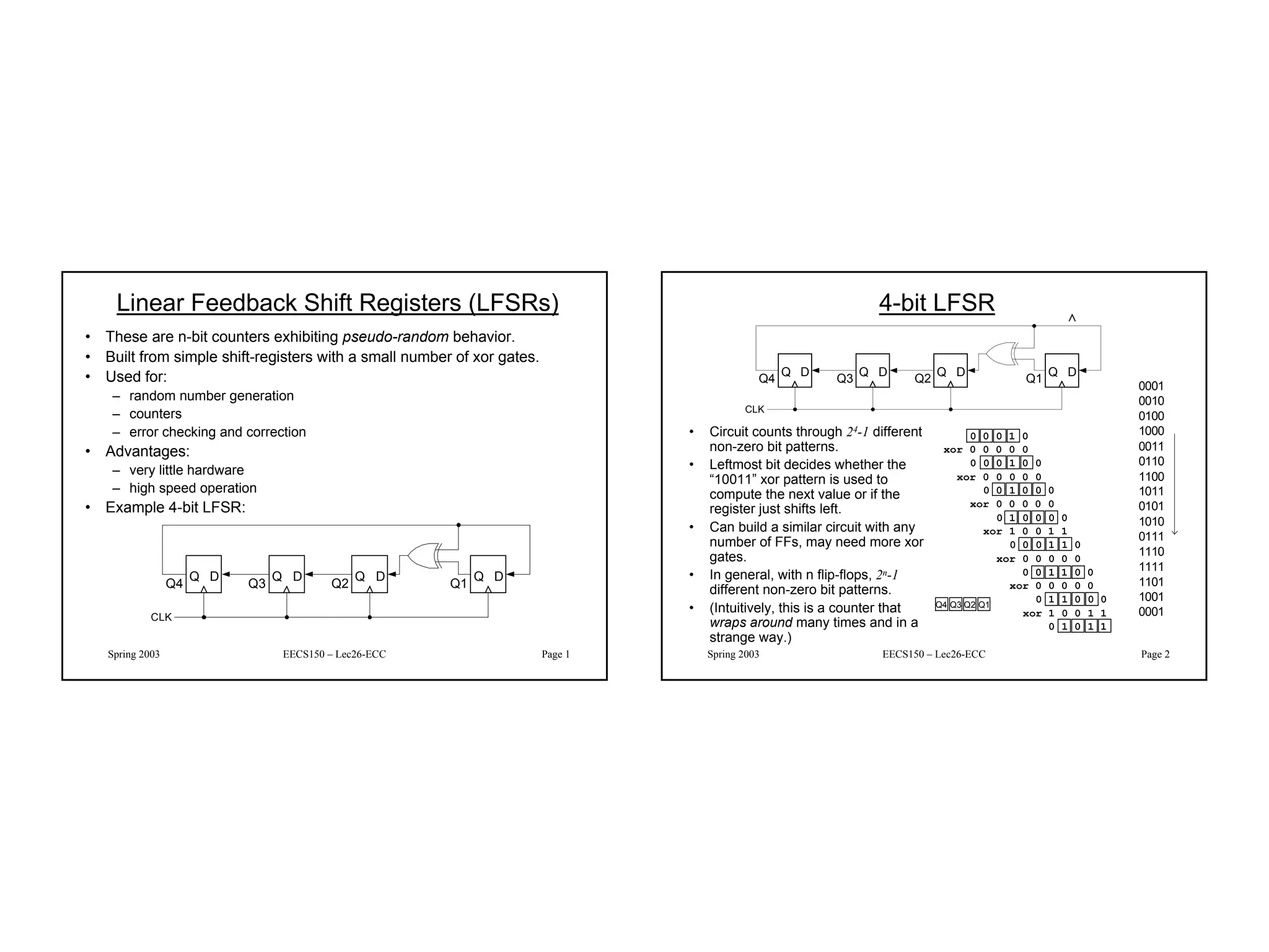
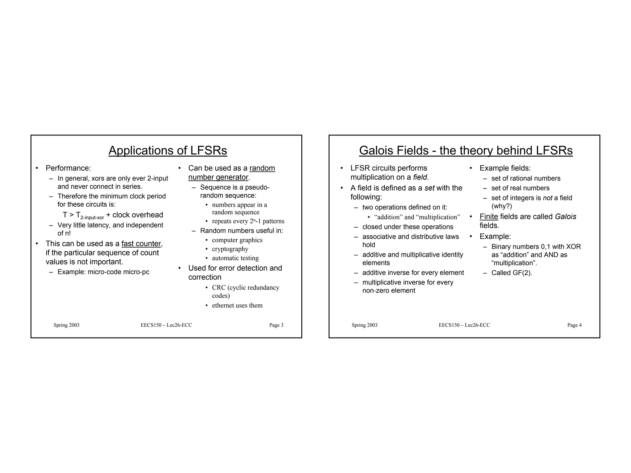
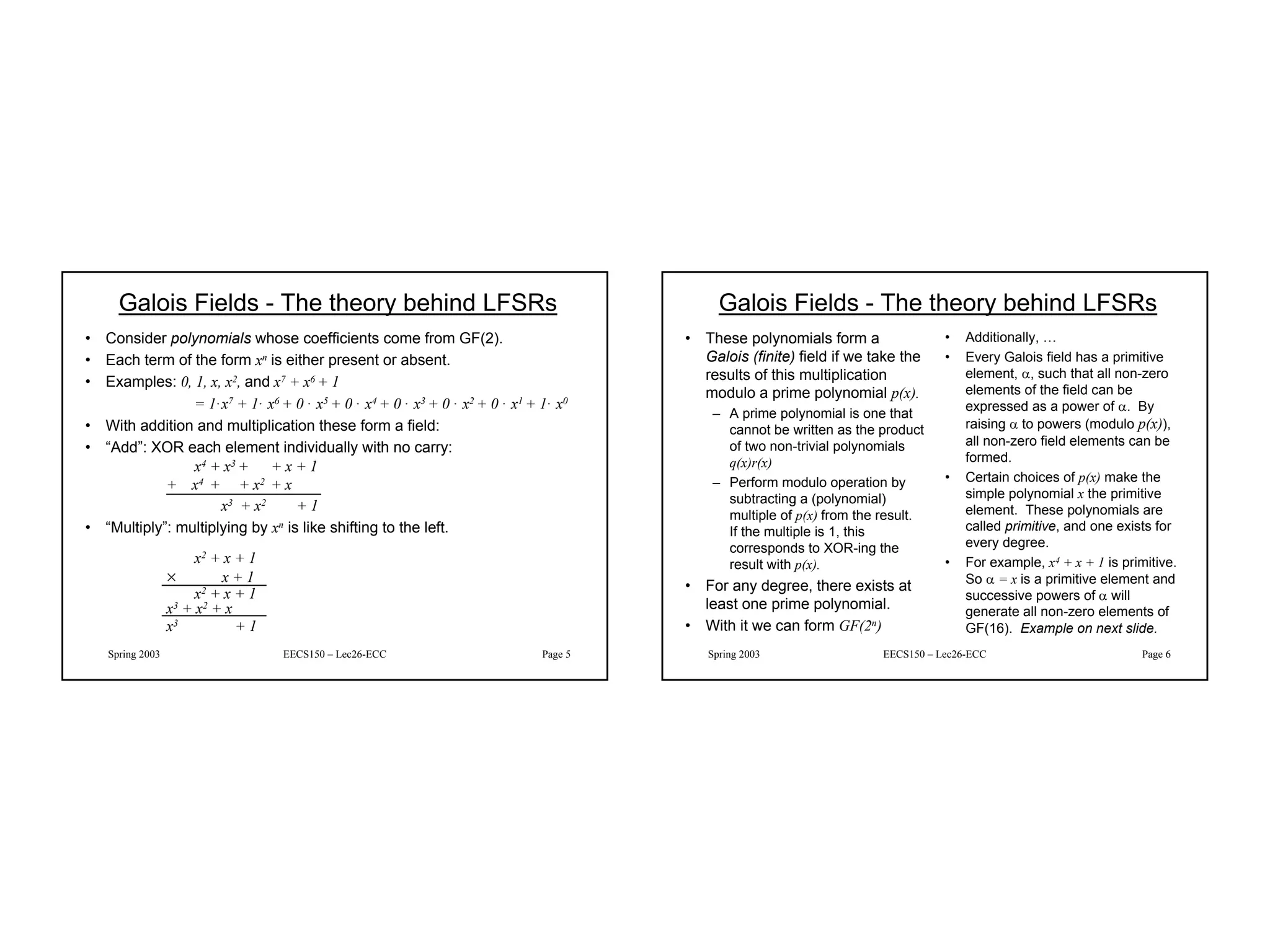
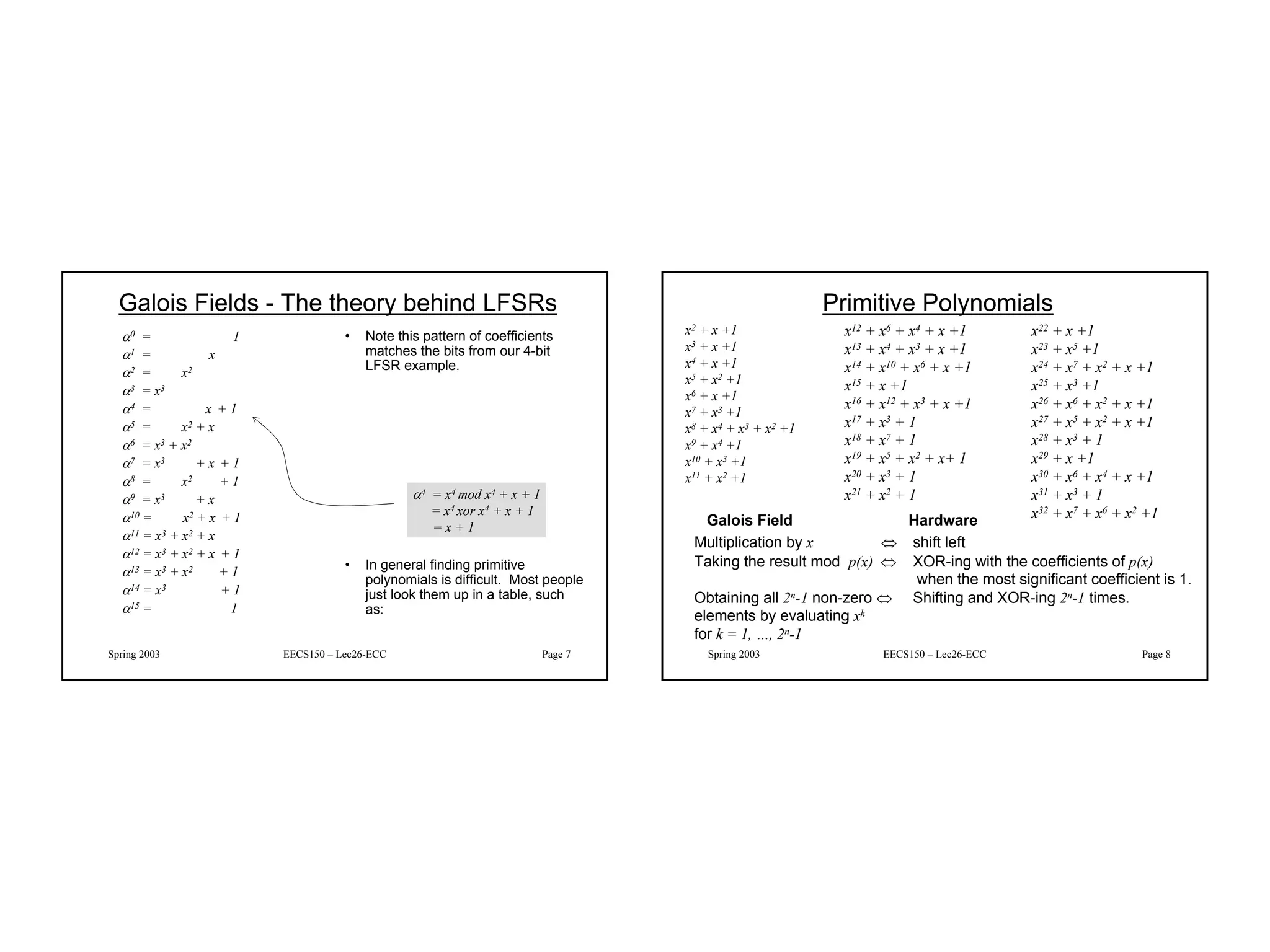
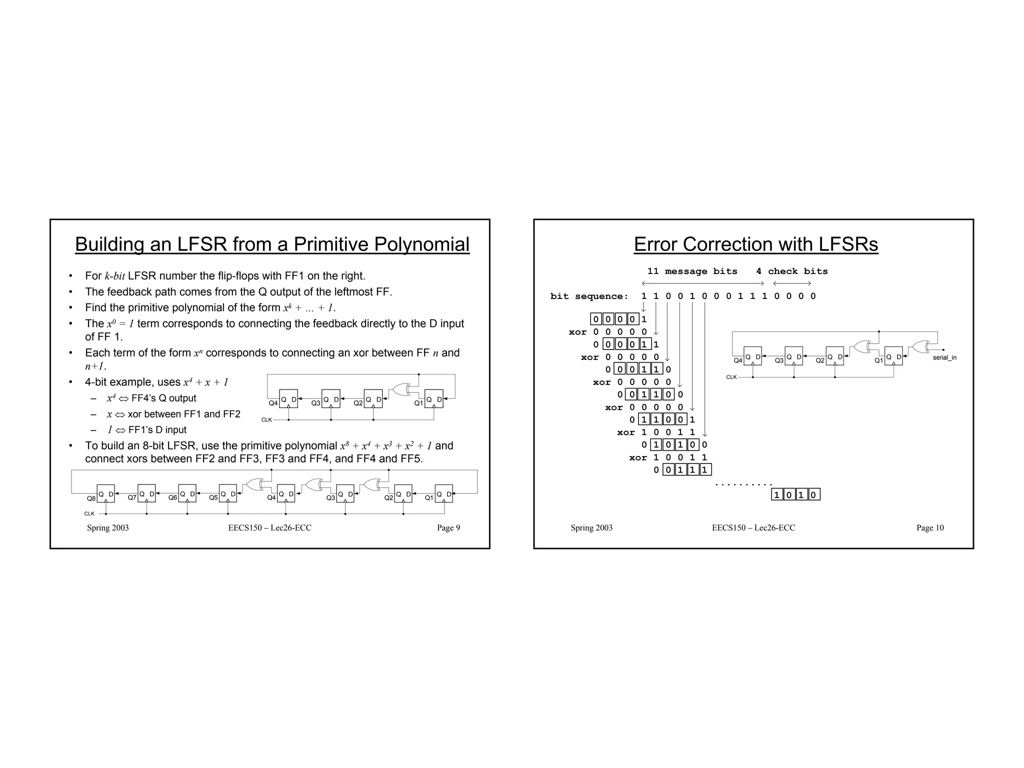
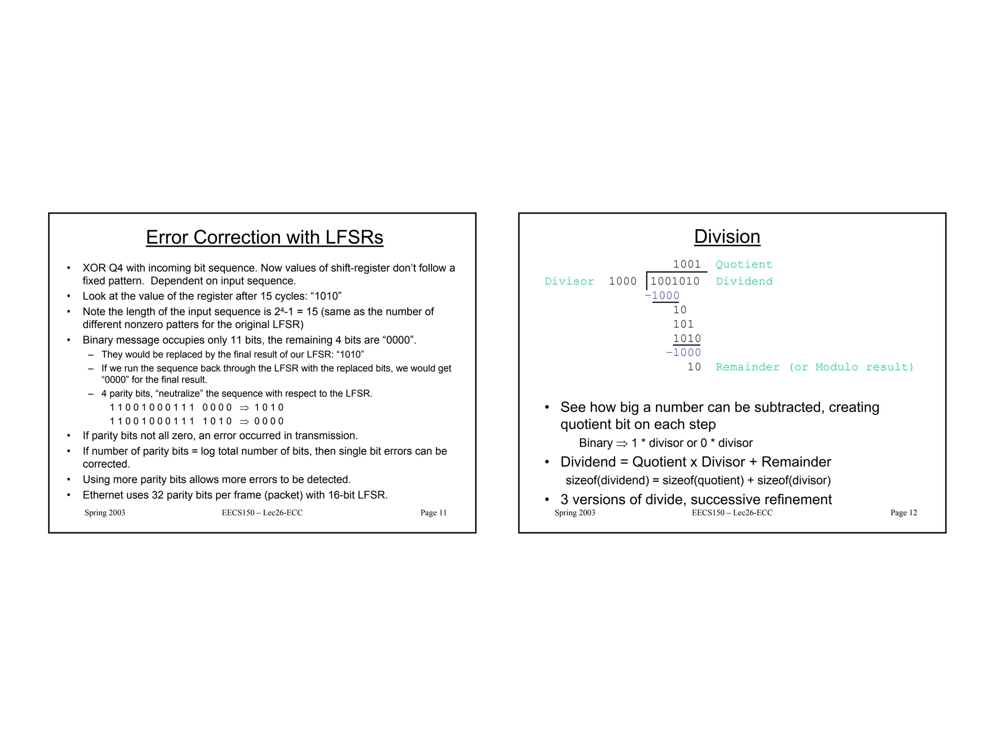
Coefficient of Thermal Expansion and their Importance.pptx
LFSR Lecture
1. 1
Spring 2003 EECS150 – Lec26-ECC Page 1
Linear Feedback Shift Registers (LFSRs)
• These are n-bit counters exhibiting pseudo-random behavior.
• Built from simple shift-registers with a small number of xor gates.
• Used for:
– random number generation
– counters
– error checking and correction
• Advantages:
– very little hardware
– high speed operation
• Example 4-bit LFSR:
Q D
Q1
Q D
Q2
Q D
Q3
Q D
Q4
CLK
Spring 2003 EECS150 – Lec26-ECC Page 2
4-bit LFSR
• Circuit counts through 24-1 different
non-zero bit patterns.
• Leftmost bit decides whether the
“10011” xor pattern is used to
compute the next value or if the
register just shifts left.
• Can build a similar circuit with any
number of FFs, may need more xor
gates.
• In general, with n flip-flops, 2n-1
different non-zero bit patterns.
• (Intuitively, this is a counter that
wraps around many times and in a
strange way.)
0 0 0 1 0
xor 0 0 0 0 0
0 0 0 1 0 0
xor 0 0 0 0 0
0 0 1 0 0 0
xor 0 0 0 0 0
0 1 0 0 0 0
xor 1 0 0 1 1
0 0 0 1 1 0
xor 0 0 0 0 0
0 0 1 1 0 0
xor 0 0 0 0 0
0 1 1 0 0 0
xor 1 0 0 1 1
0 1 0 1 1
Q4 Q3 Q2 Q1
0001
0010
0100
1000
0011
0110
1100
1011
0101
1010
0111
1110
1111
1101
1001
0001
Q D
Q1
Q D
Q2
Q D
Q3
Q D
Q4
CLK
2. 2
Spring 2003 EECS150 – Lec26-ECC Page 3
Applications of LFSRs
• Performance:
– In general, xors are only ever 2-input
and never connect in series.
– Therefore the minimum clock period
for these circuits is:
T > T2-input-xor + clock overhead
– Very little latency, and independent
of n!
• This can be used as a fast counter,
if the particular sequence of count
values is not important.
– Example: micro-code micro-pc
• Can be used as a random
number generator.
– Sequence is a pseudo-
random sequence:
• numbers appear in a
random sequence
• repeats every 2n-1 patterns
– Random numbers useful in:
• computer graphics
• cryptography
• automatic testing
• Used for error detection and
correction
• CRC (cyclic redundancy
codes)
• ethernet uses them
Spring 2003 EECS150 – Lec26-ECC Page 4
Galois Fields - the theory behind LFSRs
• LFSR circuits performs
multiplication on a field.
• A field is defined as a set with the
following:
– two operations defined on it:
• “addition” and “multiplication”
– closed under these operations
– associative and distributive laws
hold
– additive and multiplicative identity
elements
– additive inverse for every element
– multiplicative inverse for every
non-zero element
• Example fields:
– set of rational numbers
– set of real numbers
– set of integers is not a field
(why?)
• Finite fields are called Galois
fields.
• Example:
– Binary numbers 0,1 with XOR
as “addition” and AND as
“multiplication”.
– Called GF(2).
3. 3
Spring 2003 EECS150 – Lec26-ECC Page 5
Galois Fields - The theory behind LFSRs
• Consider polynomials whose coefficients come from GF(2).
• Each term of the form xn is either present or absent.
• Examples: 0, 1, x, x2, and x7 + x6 + 1
= 1·x7 + 1· x6 + 0 · x5 + 0 · x4 + 0 · x3 + 0 · x2 + 0 · x1 + 1· x0
• With addition and multiplication these form a field:
• “Add”: XOR each element individually with no carry:
x4 + x3 + + x + 1
+ x4 + + x2 + x
x3 + x2 + 1
• “Multiply”: multiplying by xn is like shifting to the left.
x2 + x + 1
× x + 1
x2 + x + 1
x3 + x2 + x
x3 + 1
Spring 2003 EECS150 – Lec26-ECC Page 6
Galois Fields - The theory behind LFSRs
• These polynomials form a
Galois (finite) field if we take the
results of this multiplication
modulo a prime polynomial p(x).
– A prime polynomial is one that
cannot be written as the product
of two non-trivial polynomials
q(x)r(x)
– Perform modulo operation by
subtracting a (polynomial)
multiple of p(x) from the result.
If the multiple is 1, this
corresponds to XOR-ing the
result with p(x).
• For any degree, there exists at
least one prime polynomial.
• With it we can form GF(2n)
• Additionally, …
• Every Galois field has a primitive
element, α, such that all non-zero
elements of the field can be
expressed as a power of α. By
raising α to powers (modulo p(x)),
all non-zero field elements can be
formed.
• Certain choices of p(x) make the
simple polynomial x the primitive
element. These polynomials are
called primitive, and one exists for
every degree.
• For example, x4 + x + 1 is primitive.
So α = x is a primitive element and
successive powers of α will
generate all non-zero elements of
GF(16). Example on next slide.
4. 4
Spring 2003 EECS150 – Lec26-ECC Page 7
Galois Fields - The theory behind LFSRs
α0 = 1
α1 = x
α2 = x2
α3 = x3
α4 = x + 1
α5 = x2 + x
α6 = x3 + x2
α7 = x3 + x + 1
α8 = x2 + 1
α9 = x3 + x
α10 = x2 + x + 1
α11 = x3 + x2 + x
α12 = x3 + x2 + x + 1
α13 = x3 + x2 + 1
α14 = x3 + 1
α15 = 1
• Note this pattern of coefficients
matches the bits from our 4-bit
LFSR example.
• In general finding primitive
polynomials is difficult. Most people
just look them up in a table, such
as:
α4 = x4 mod x4 + x + 1
= x4 xor x4 + x + 1
= x + 1
Spring 2003 EECS150 – Lec26-ECC Page 8
Primitive Polynomials
x2 + x +1
x3 + x +1
x4 + x +1
x5 + x2 +1
x6 + x +1
x7 + x3 +1
x8 + x4 + x3 + x2 +1
x9 + x4 +1
x10 + x3 +1
x11 + x2 +1
x12 + x6 + x4 + x +1
x13 + x4 + x3 + x +1
x14 + x10 + x6 + x +1
x15 + x +1
x16 + x12 + x3 + x +1
x17 + x3 + 1
x18 + x7 + 1
x19 + x5 + x2 + x+ 1
x20 + x3 + 1
x21 + x2 + 1
x22 + x +1
x23 + x5 +1
x24 + x7 + x2 + x +1
x25 + x3 +1
x26 + x6 + x2 + x +1
x27 + x5 + x2 + x +1
x28 + x3 + 1
x29 + x +1
x30 + x6 + x4 + x +1
x31 + x3 + 1
x32 + x7 + x6 + x2 +1
Galois Field Hardware
Multiplication by x ⇔ shift left
Taking the result mod p(x) ⇔ XOR-ing with the coefficients of p(x)
when the most significant coefficient is 1.
Obtaining all 2n-1 non-zero ⇔ Shifting and XOR-ing 2n-1 times.
elements by evaluating xk
for k = 1, …, 2n-1
5. 5
Spring 2003 EECS150 – Lec26-ECC Page 9
Building an LFSR from a Primitive Polynomial
• For k-bit LFSR number the flip-flops with FF1 on the right.
• The feedback path comes from the Q output of the leftmost FF.
• Find the primitive polynomial of the form xk + … + 1.
• The x0 = 1 term corresponds to connecting the feedback directly to the D input
of FF 1.
• Each term of the form xn corresponds to connecting an xor between FF n and
n+1.
• 4-bit example, uses x4 + x + 1
– x4 ⇔ FF4’s Q output
– x ⇔ xor between FF1 and FF2
– 1 ⇔ FF1’s D input
• To build an 8-bit LFSR, use the primitive polynomial x8 + x4 + x3 + x2 + 1 and
connect xors between FF2 and FF3, FF3 and FF4, and FF4 and FF5.
Q D
Q1
Q D
Q2
Q D
Q3
Q D
Q4
CLK
Q D
Q4
Q D
Q5
Q D
Q6
Q D
Q7
CLK
Q D
Q3
Q D
Q2
Q D
Q1
Q8
Q D
Spring 2003 EECS150 – Lec26-ECC Page 10
Error Correction with LFSRs
Q D
Q1
Q D
Q2
Q D
Q3
Q D
Q4
CLK
serial_in
0 0 0 0 1
xor 0 0 0 0 0
0 0 0 0 1 1
xor 0 0 0 0 0
0 0 0 1 1 0
xor 0 0 0 0 0
0 0 1 1 0 0
xor 0 0 0 0 0
0 1 1 0 0 1
xor 1 0 0 1 1
0 1 0 1 0 0
xor 1 0 0 1 1
0 0 1 1 1
..........
1 0 1 0
11 message bits 4 check bits
bit sequence: 1 1 0 0 1 0 0 0 1 1 1 0 0 0 0
6. 6
Spring 2003 EECS150 – Lec26-ECC Page 11
Error Correction with LFSRs
• XOR Q4 with incoming bit sequence. Now values of shift-register don’t follow a
fixed pattern. Dependent on input sequence.
• Look at the value of the register after 15 cycles: “1010”
• Note the length of the input sequence is 24-1 = 15 (same as the number of
different nonzero patters for the original LFSR)
• Binary message occupies only 11 bits, the remaining 4 bits are “0000”.
– They would be replaced by the final result of our LFSR: “1010”
– If we run the sequence back through the LFSR with the replaced bits, we would get
“0000” for the final result.
– 4 parity bits, “neutralize” the sequence with respect to the LFSR.
1 1 0 0 1 0 0 0 1 1 1 0 0 0 0 ⇒ 1 0 1 0
1 1 0 0 1 0 0 0 1 1 1 1 0 1 0 ⇒ 0 0 0 0
• If parity bits not all zero, an error occurred in transmission.
• If number of parity bits = log total number of bits, then single bit errors can be
corrected.
• Using more parity bits allows more errors to be detected.
• Ethernet uses 32 parity bits per frame (packet) with 16-bit LFSR.
Spring 2003 EECS150 – Lec26-ECC Page 12
Division
1001 Quotient
Divisor 1000 1001010 Dividend
–1000
10
101
1010
–1000
10 Remainder (or Modulo result)
• See how big a number can be subtracted, creating
quotient bit on each step
Binary ⇒ 1 * divisor or 0 * divisor
• Dividend = Quotient x Divisor + Remainder
sizeof(dividend) = sizeof(quotient) + sizeof(divisor)
• 3 versions of divide, successive refinement
7. 7
Spring 2003 EECS150 – Lec26-ECC Page 13
DIVIDE HARDWARE Version 1
• 64-bit Divisor register, 64-bit adder/subtractor, 64-bit
Remainder register, 32-bit Quotient register
Remainder
Quotient
Divisor
add/sub
Shift Right
Shift Left
Write
Control
32 bits
64 bits
64 bits
Spring 2003 EECS150 – Lec26-ECC Page 14
2b. Restore the original value by adding the
Divisor register to the Remainder register, &
place the sum in the Remainder register. Also
shift the Quotient register to the left, setting
the new least significant bit to 0.
Divide Algorithm Version 1
Takes n+1 steps for n-bit Quotient & Rem.
Remainder Quotient Divisor
00000111 0000 00100000
710 210
Test
Remainder
Remainder < 0
Remainder≥ 0
1. Subtract the Divisor register from the
Remainder register, and place the result
in the Remainder register.
2a. Shift the
Quotient register
to the left setting
the new rightmost
bit to 1.
3. Shift the Divisor register right 1 bit.
Done
Yes: n+1 repetitions (n = 4 here)
Start: Place Dividend in Remainder
n+1
repetition?
No: < n+1 repetitions
8. 8
Spring 2003 EECS150 – Lec26-ECC Page 15
Version 1 Division Example 7/2
Iteration step quotient divisor remainder
0 Initial values 0000 0010 0000 0000 0111
1 1: rem=rem-div 0000 0010 0000 1110 0111
2b: rem<0 ⇒ +div, sll Q, Q0=0 0000 0010 0000 0000 0111
3: shift div right 0000 0001 0000 0000 0111
2 1: rem=rem-div 0000 0001 0000 1111 0111
2b: rem<0 ⇒ +div, sll Q, Q0=0 0000 0001 0000 0000 0111
3: shift div right 0000 0000 1000 0000 0111
3 1: rem=rem-div 0000 0000 1000 1111 1111
2b: rem<0 ⇒ +div, sll Q, Q0=0 0000 0000 1000 0000 0111
3: shift div right 0000 0000 0100 0000 0111
4 1: rem=rem-div 0000 0000 0100 0000 0011
2a: rem≥0 ⇒ sll Q, Q0=1 0001 0000 0100 0000 0011
3: shift div right 0001 0000 0010 0000 0011
5 1: rem=rem-div 0001 0000 0010 0000 0001
2a: rem≥0 ⇒ sll Q, Q0=1 0011 0000 0010 0000 0001
3: shift div right 0011 0000 0001 0000 0001
Spring 2003 EECS150 – Lec26-ECC Page 16
Observations on Divide Version 1
• 1/2 bits in divisor always 0
⇒ 1/2 of 64-bit adder is wasted
⇒ 1/2 of divisor is wasted
• Instead of shifting divisor to right,
shift remainder to left?
• 1st step cannot produce a 1 in quotient bit
(otherwise quotient ≥ 2n)
⇒ switch order to shift first and then subtract,
can save 1 iteration
9. 9
Spring 2003 EECS150 – Lec26-ECC Page 17
DIVIDE HARDWARE Version 2
• 32-bit Divisor register, 32-bit ALU, 64-bit Remainder
register, 32-bit Quotient register
Remainder
Quotient
Divisor
add/sub
Shift Left
Write
Control
32 bits
32 bits
64 bits
Shift Left
Spring 2003 EECS150 – Lec26-ECC Page 18
Divide Algorithm Version 2
Remainder Quotient Divisor
00000111 0000 0010
710 210
3b. Restore the original value by adding the Divisor
register to the left half of the Remainder register,
&place the sum in the left half of the Remainder
register. Also shift the Quotient register to the left,
setting the new least significant bit to 0.
Test
Remainder
Remainder < 0
Remainder ≥ 0
2. Subtract the Divisor register from the
left half of the Remainder register, & place the
result in the left half of the Remainder register.
3a. Shift the
Quotient register
to the left setting
the new rightmost
bit to 1.
1. Shift the Remainder register left 1 bit.
Done
Yes: n repetitions (n = 4 here)
nth
repetition?
No: < n repetitions
Start: Place Dividend in Remainder
10. 10
Spring 2003 EECS150 – Lec26-ECC Page 19
Observations on Divide Version 2
• Eliminate Quotient register by combining with Remainder
as shifted left.
– Start by shifting the Remainder left as before.
– Thereafter loop contains only two steps because the shifting of
the Remainder register shifts both the remainder in the left half
and the quotient in the right half
– The consequence of combining the two registers together and
the new order of the operations in the loop is that the remainder
will shifted left one time too many.
– Thus the final correction step must shift back only the remainder
in the left half of the register
Spring 2003 EECS150 – Lec26-ECC Page 20
DIVIDE HARDWARE Version 3
• 32-bit Divisor register, 32-bit adder/subtractor, 64-bit
Remainder register, (0-bit Quotient reg)
Remainder (Quotient)
Divisor
32-bit ALU
Write
Control
32 bits
64 bits
Shift Left
“HI” “LO”
11. 11
Spring 2003 EECS150 – Lec26-ECC Page 21
Divide Algorithm Version 3
Remainder Divisor
0000 0111 0010
710 210
3b. Restore the original value by adding the Divisor
register to the left half of the Remainder register,
&place the sum in the left half of the Remainder
register. Also shift the Remainder register to the
left, setting the new least significant bit to 0.
Test
Remainder
Remainder < 0
Remainder ≥ 0
2. Subtract the Divisor register from the
left half of the Remainder register, & place the
result in the left half of the Remainder register.
3a. Shift the
Remainder register
to the left setting
the new rightmost
bit to 1.
1. Shift the Remainder register left 1 bit.
Done. Shift left half of Remainder right 1 bit.
Yes: n repetitions (n = 4 here)
nth
repetition?
No: < n repetitions
Start: Place Dividend in Remainder
*upper-half
Spring 2003 EECS150 – Lec26-ECC Page 22
Observations on Divide Version 3
• Same Hardware as shift and add multiplier: just 63-bit
register to shift left or shift right
• Signed divides: Simplest is to remember signs, make
positive, and complement quotient and remainder if
necessary
– Note: Dividend and Remainder must have same sign
– Note: Quotient negated if Divisor sign & Dividend sign disagree
e.g., –7 ÷ 2 = –3, remainder = –1
• Possible for quotient to be too large: if divide 64-bit
integer by 1, quotient is 64 bits (“called saturation”)