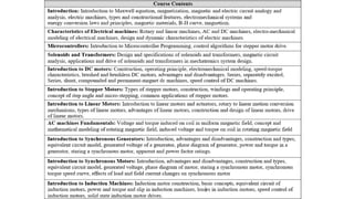
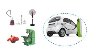
Dr. Arsalan Arif
Electrical Machine Drives
Fall Semester 2022
Electrical machinery Fundamentals
Stephen J. Chapman
 Control and design of machine drives
 Induction motor
 Vernier machine
 Brushless wound rotor synchronous machine
 Application
 Electric cars
A.Arif, N. Baloch and B. Kwon, "Winding Switching and Turn Switching in Permanent Magnet Vernier Machines for Wide
Speed Range Operation and High Efficiency," in IEEE Access, vol. 7, pp. 55344-55357, 2019, doi:
10.1109/ACCESS.2019.2912181.
A. Arif, N. Baloch and B. I. Kwon, "Wide speed range operation of permanent magnet vernier machines," in Electronics
Letters, vol. 54, no. 18, pp. 1070-1072, 6 9 2018, doi: 10.1049/el.2018.5008.
 Low speed small electric cars ( Golf Carts etc)
A. Arif, N. Baloch, M. Ayub and B. -I. Kwon, "Wide-Speed Range Operation of PM Vernier Machines Using Wye and Wye-
delta winding Configurations," in IEEE Access, doi: 10.1109/ACCESS.2020.3023763.
Hanynag University, South Korea
1. Farhan Arif, Qasim Ali Quereshi, Arsalan Arif, et. al. “Novel rotor harmonic winding configuration for the Brushless wound r
otor synchronous machine”, Electrical Engineering, Springer. (Under review)
2. A. Arif, N. Baloch and B. Kwon, " Wide-Speed Range Operation of PM Vernier Machines Using Wye and Wye-delta winding
Configurations," in IEEE ACCESS
3. A. Arif, N. Baloch and B. Kwon, "Winding Switching and Turn Switching in Permanent Magnet Vernier Machines for Wide S
peed Range Operation and High Efficiency," in IEEE Access, vol. 7, pp. 55344-55357, 2019, doi: 10.1109/ACCESS.2019.29
12181.
4. A. Arif, N. Baloch and B. I. Kwon, "Wide speed range operation of permanent magnet vernier machines," in Electronics Lett
ers, vol. 54, no. 18, pp. 1070-1072, 6 9 2018, doi: 10.1049/el.2018.5008.
5. Muhammad Ayub et al. “Utilization of Reluctance Torque for Improvement of the Starting and Average Torques of a Brushles
s Wound Field Synchronous Machine” in Electrical Engineering
6. Muhammad Waseem Khan, Arsalan Arif, “Automizing DC and Induction Motors Based System Through GSM Technology”,
international Journal of Scientific & Engineering Research Volume 4, Issue 2, February-2013 1, ISSN 2229-5518
7. Arif Arsalan. Ki Kwang Park, Lee Sun Young, Yang Hai Won, “Rotor Resistance Estimation of induction Motor using Non-Li
near disturbance observer” 40th KIEE summer conference 17 July 2009
8. A. Arif, Muhammad Ayub and B. Kwon “Three Phase Brushless Synchronous Generator Topology Without and Exciter with
Experimental Verification” 2022-MMM Intermag.
General Papers
Muhammad Umair Shafiq, Ijlal Ullah Khan, Abid Imran, Arsalan Arif, Wasim Ahmed Khan, “Collaborative Robot with Collision
Avoidance System, “Functional Reverse Engineering of Machine Tools”
Book Chapter
Electrical Machine
Device which converts either electrical Energy into mechanical energy or vice versa
Motor
Converts electrical energy into mechanical energy
Generator
Converts mechanical energy into electrical energy
Transformer
Converts ac electrical voltage from one level to another
Step up Transformer Step down Transformer
Power=VI Loss= 𝐼2
𝑅
Shaft
 Most of the electric machines rotates about an axis called Shaft
 Counterclockwise rotation as positive
 Clockwise rotation as negative
Angular Velocity
 Rate of change of angular position w.r.t. time
 Positive for counterclockwise direction
 Negative for clockwise direction
v= 𝑑𝑟
𝑑𝑡
𝑟𝑎𝑑
𝑠𝑒𝑐
𝑟𝑒𝑣
𝑚𝑖𝑛
𝜔𝑚 Angular velocity expressed in radians per second
𝑓𝑚 Angular velocity expressed in revolution per second
𝑛𝑚 Angular velocity expressed in revolution per minutes
𝑓𝑚 =
𝜔𝑚
2𝜋
ω= 𝑑θ
𝑑𝑡
𝑛𝑚 = 60𝑓𝑚 𝑛𝑚 =
𝜔𝑚
60
Angular Acceleration
 Rate of change of angular velocity w.r.t. time
 Positive if angular velocity is increasing
 Negative if angular velocity is decreasing
a= 𝑑𝑟
𝑑𝑡
α= 𝑑ω
𝑑𝑡
𝑟𝑎𝑑
𝑠𝑒𝑐2
Torque
 For linear motion force is applied to change velocity
 The greater the force the more rapidly its velocity changes.
 For angular motion, the angular velocity is constant, unless toque is applied to it.
 Greater the torque, more rapidly the angular velocity changes
T=F×r
θ
180-θ
𝑟 sin(180 − 𝜃) = 𝑟 sin 𝜃
F
r
Torque depends on
 Magnitude of the applied force.
 Distance between the axis of rotation and the line of action of force (Moment arm)
τ= 0
F F
τ= 0
F F
θ
180-θ
𝑟 sin(180 − 𝜃) = 𝑟 sin 𝜃
F
r
Torque on an object can be defined as the product of the force applied to the object and the smallest
distance between the line of action of force and the object axis of rotation.
Τ= (F)(𝑟 sin 𝜃)
= 𝑟𝐹 sin 𝜃
Nm
= 𝑟(sin 180. cos 𝜃 − sin 𝜃 cos 180)
Newton Law of rotation
If force is applied to an object of mass m then it will cause acceleration in that object
T= Jα
Where J is moment of inertia
Work
If torque is applied to an object, it will result in angular acceleration. This relation is called newton
law of rotation
F= ma
For linear motion, the force applied through a distance is called work
𝑊 = 𝐹𝑑𝑟
If a constant force is applied colinear with the direction of motion, then
𝑊 = 𝐹𝑟 joules
It is the quantity that determines the torque needed for desired
angular acceleration. Tendency of an object to resist angular
velocity
Work
In rotational motion, the torque applied through an angle is called work
𝑊 = τ𝑑θ
If a constant torque is applied, then
𝑊 = τθ
Power
Rate of doing work, or increase in work per unit time
𝑃 =
𝑑𝑊
𝑑𝑡
Joules/sec watts
Foot-pounds/sec Horsepower
Power
𝑃 =
𝑑𝑊
𝑑𝑡
𝑃 =
𝑑(𝐹𝑟)
𝑑𝑡
= 𝐹
𝑑𝑟
𝑑𝑡
= 𝐹𝑣
Assuming force is constant Assuming torque is constant
𝑃 =
𝑑𝑊
𝑑𝑡
𝑃 =
𝑑(τθ)
𝑑𝑡
𝑃 =
τ𝑑(θ)
𝑑𝑡
𝑃 = τω
Very important equation as it can describe the mechanical power on the shaft of motor or Generator
1 H. P = 746 𝑊𝑎𝑡𝑡𝑠
The definition of 1 Horsepower is displacing 1 lb. 33,000 ft. in one minute or 33,000 lb-ft / minute.
It was determined that a horse is capable of performing 33,000 ft-lbf of work per min.
A magnetic field is a picture that we use as a tool to describe how the magnetic force is distributed
in the space around and within something magnetic.
Magnetic Field
It is fundamental mechanism by which energy is converted from one form to another in motors,
generators and transformers
2. A current-carrying wire in the presence of a magnetic field has a force induced
on it
3. A moving wire in the presence of a magnetic field has a voltage induced in it
4. A time-changing magnetic field induces a voltage in a coil of wire if it passes
through that coil
1. A current-carrying wire produces a magnetic field in the area around it.
Generator
Action
Transformer
Action
Magnetic Field
Four basic principles describe how magnetic fields are used in these devices:
Motor
Action
Ampere’s Law
The magnetic field in space around an electric current is proportional to the electric current which serves
as its source.
𝐻. 𝑑𝑙 = 𝐼𝑛𝑒𝑡
A useful law that relates the net magnetic field along a closed loop to the electric current passing
through the loop.
Basic law that controls the production of magnetic field by current.
𝐻 is the magnetic field intensity produces by the current 𝐼𝑛𝑒𝑡
The current passing within the path of integration 𝐼𝑛𝑒𝑡 is Ni.
Since the coil of wire (carrying the current i) cuts the path, N
times.
𝐻𝑙𝑐 = 𝑁𝑖
𝐻 =
𝑁𝑖
𝑙𝑐
Magnetic Field Intensity
Measure of the "effort " that a current is putting into the establishment of a magnetic field.
The measure of force that a current is applying to establish the magnetic field.
The relationship between the magnetic field intensity H and the resulting magnetic flux density B
produced within a material is given by
𝐵 = 𝜇𝐻
𝐻 =
𝑁𝑖
𝑙𝑐
The strength of the magnetic field produced in the core also depends on the material of the core.
𝜇 = 𝜇0𝜇𝑟 𝜇0 = 4𝜋 10−7 𝐻
𝑚
Permeability of any other material compared to the permeability of free space is called its relative
permeability 𝜇𝑟
Magnetic Flux Density
is a measurement of the flux per unit area
Magnetic flux density is given as
𝐵 = 𝜇𝐻
𝜇 is permeability of the material 𝜇 = 𝜇𝑜𝜇𝑟
𝜇𝑜 is the permeability of the free space = 4𝜋 × 10−7
H/m
Total flux in an area is given as
𝜑 = 𝐵. 𝑑𝐴
If the area is perpendicular to flux density vector, then
𝜑 = 𝐵𝐴
𝜑 =
𝜇𝑁𝑖𝐴
𝑙𝑐
Permeability is the resistance of material
against the formation of magnetic field
Magnetic
Field
B
BAcosθ
𝐻 =
𝑁𝑖
𝑙𝑐
𝐵 = 𝜇𝐻

Machines drive 1.pptx

  • 1.
    Dr. Arsalan Arif ElectricalMachine Drives Fall Semester 2022 Electrical machinery Fundamentals Stephen J. Chapman
  • 2.
     Control anddesign of machine drives  Induction motor  Vernier machine  Brushless wound rotor synchronous machine  Application  Electric cars A.Arif, N. Baloch and B. Kwon, "Winding Switching and Turn Switching in Permanent Magnet Vernier Machines for Wide Speed Range Operation and High Efficiency," in IEEE Access, vol. 7, pp. 55344-55357, 2019, doi: 10.1109/ACCESS.2019.2912181. A. Arif, N. Baloch and B. I. Kwon, "Wide speed range operation of permanent magnet vernier machines," in Electronics Letters, vol. 54, no. 18, pp. 1070-1072, 6 9 2018, doi: 10.1049/el.2018.5008.  Low speed small electric cars ( Golf Carts etc) A. Arif, N. Baloch, M. Ayub and B. -I. Kwon, "Wide-Speed Range Operation of PM Vernier Machines Using Wye and Wye- delta winding Configurations," in IEEE Access, doi: 10.1109/ACCESS.2020.3023763. Hanynag University, South Korea
  • 3.
    1. Farhan Arif,Qasim Ali Quereshi, Arsalan Arif, et. al. “Novel rotor harmonic winding configuration for the Brushless wound r otor synchronous machine”, Electrical Engineering, Springer. (Under review) 2. A. Arif, N. Baloch and B. Kwon, " Wide-Speed Range Operation of PM Vernier Machines Using Wye and Wye-delta winding Configurations," in IEEE ACCESS 3. A. Arif, N. Baloch and B. Kwon, "Winding Switching and Turn Switching in Permanent Magnet Vernier Machines for Wide S peed Range Operation and High Efficiency," in IEEE Access, vol. 7, pp. 55344-55357, 2019, doi: 10.1109/ACCESS.2019.29 12181. 4. A. Arif, N. Baloch and B. I. Kwon, "Wide speed range operation of permanent magnet vernier machines," in Electronics Lett ers, vol. 54, no. 18, pp. 1070-1072, 6 9 2018, doi: 10.1049/el.2018.5008. 5. Muhammad Ayub et al. “Utilization of Reluctance Torque for Improvement of the Starting and Average Torques of a Brushles s Wound Field Synchronous Machine” in Electrical Engineering 6. Muhammad Waseem Khan, Arsalan Arif, “Automizing DC and Induction Motors Based System Through GSM Technology”, international Journal of Scientific & Engineering Research Volume 4, Issue 2, February-2013 1, ISSN 2229-5518 7. Arif Arsalan. Ki Kwang Park, Lee Sun Young, Yang Hai Won, “Rotor Resistance Estimation of induction Motor using Non-Li near disturbance observer” 40th KIEE summer conference 17 July 2009 8. A. Arif, Muhammad Ayub and B. Kwon “Three Phase Brushless Synchronous Generator Topology Without and Exciter with Experimental Verification” 2022-MMM Intermag. General Papers Muhammad Umair Shafiq, Ijlal Ullah Khan, Abid Imran, Arsalan Arif, Wasim Ahmed Khan, “Collaborative Robot with Collision Avoidance System, “Functional Reverse Engineering of Machine Tools” Book Chapter
  • 6.
    Electrical Machine Device whichconverts either electrical Energy into mechanical energy or vice versa Motor Converts electrical energy into mechanical energy Generator Converts mechanical energy into electrical energy Transformer Converts ac electrical voltage from one level to another Step up Transformer Step down Transformer Power=VI Loss= 𝐼2 𝑅
  • 7.
    Shaft  Most ofthe electric machines rotates about an axis called Shaft  Counterclockwise rotation as positive  Clockwise rotation as negative Angular Velocity  Rate of change of angular position w.r.t. time  Positive for counterclockwise direction  Negative for clockwise direction v= 𝑑𝑟 𝑑𝑡 𝑟𝑎𝑑 𝑠𝑒𝑐 𝑟𝑒𝑣 𝑚𝑖𝑛 𝜔𝑚 Angular velocity expressed in radians per second 𝑓𝑚 Angular velocity expressed in revolution per second 𝑛𝑚 Angular velocity expressed in revolution per minutes 𝑓𝑚 = 𝜔𝑚 2𝜋 ω= 𝑑θ 𝑑𝑡 𝑛𝑚 = 60𝑓𝑚 𝑛𝑚 = 𝜔𝑚 60
  • 8.
    Angular Acceleration  Rateof change of angular velocity w.r.t. time  Positive if angular velocity is increasing  Negative if angular velocity is decreasing a= 𝑑𝑟 𝑑𝑡 α= 𝑑ω 𝑑𝑡 𝑟𝑎𝑑 𝑠𝑒𝑐2 Torque  For linear motion force is applied to change velocity  The greater the force the more rapidly its velocity changes.  For angular motion, the angular velocity is constant, unless toque is applied to it.  Greater the torque, more rapidly the angular velocity changes T=F×r
  • 9.
    θ 180-θ 𝑟 sin(180 −𝜃) = 𝑟 sin 𝜃 F r Torque depends on  Magnitude of the applied force.  Distance between the axis of rotation and the line of action of force (Moment arm) τ= 0 F F
  • 10.
    τ= 0 F F θ 180-θ 𝑟sin(180 − 𝜃) = 𝑟 sin 𝜃 F r Torque on an object can be defined as the product of the force applied to the object and the smallest distance between the line of action of force and the object axis of rotation. Τ= (F)(𝑟 sin 𝜃) = 𝑟𝐹 sin 𝜃 Nm = 𝑟(sin 180. cos 𝜃 − sin 𝜃 cos 180)
  • 11.
    Newton Law ofrotation If force is applied to an object of mass m then it will cause acceleration in that object T= Jα Where J is moment of inertia Work If torque is applied to an object, it will result in angular acceleration. This relation is called newton law of rotation F= ma For linear motion, the force applied through a distance is called work 𝑊 = 𝐹𝑑𝑟 If a constant force is applied colinear with the direction of motion, then 𝑊 = 𝐹𝑟 joules It is the quantity that determines the torque needed for desired angular acceleration. Tendency of an object to resist angular velocity
  • 12.
    Work In rotational motion,the torque applied through an angle is called work 𝑊 = τ𝑑θ If a constant torque is applied, then 𝑊 = τθ Power Rate of doing work, or increase in work per unit time 𝑃 = 𝑑𝑊 𝑑𝑡 Joules/sec watts Foot-pounds/sec Horsepower
  • 13.
    Power 𝑃 = 𝑑𝑊 𝑑𝑡 𝑃 = 𝑑(𝐹𝑟) 𝑑𝑡 =𝐹 𝑑𝑟 𝑑𝑡 = 𝐹𝑣 Assuming force is constant Assuming torque is constant 𝑃 = 𝑑𝑊 𝑑𝑡 𝑃 = 𝑑(τθ) 𝑑𝑡 𝑃 = τ𝑑(θ) 𝑑𝑡 𝑃 = τω Very important equation as it can describe the mechanical power on the shaft of motor or Generator 1 H. P = 746 𝑊𝑎𝑡𝑡𝑠 The definition of 1 Horsepower is displacing 1 lb. 33,000 ft. in one minute or 33,000 lb-ft / minute. It was determined that a horse is capable of performing 33,000 ft-lbf of work per min.
  • 14.
    A magnetic fieldis a picture that we use as a tool to describe how the magnetic force is distributed in the space around and within something magnetic. Magnetic Field It is fundamental mechanism by which energy is converted from one form to another in motors, generators and transformers
  • 15.
    2. A current-carryingwire in the presence of a magnetic field has a force induced on it 3. A moving wire in the presence of a magnetic field has a voltage induced in it 4. A time-changing magnetic field induces a voltage in a coil of wire if it passes through that coil 1. A current-carrying wire produces a magnetic field in the area around it. Generator Action Transformer Action Magnetic Field Four basic principles describe how magnetic fields are used in these devices: Motor Action
  • 16.
    Ampere’s Law The magneticfield in space around an electric current is proportional to the electric current which serves as its source. 𝐻. 𝑑𝑙 = 𝐼𝑛𝑒𝑡 A useful law that relates the net magnetic field along a closed loop to the electric current passing through the loop. Basic law that controls the production of magnetic field by current. 𝐻 is the magnetic field intensity produces by the current 𝐼𝑛𝑒𝑡 The current passing within the path of integration 𝐼𝑛𝑒𝑡 is Ni. Since the coil of wire (carrying the current i) cuts the path, N times. 𝐻𝑙𝑐 = 𝑁𝑖 𝐻 = 𝑁𝑖 𝑙𝑐 Magnetic Field Intensity
  • 17.
    Magnetic Field Intensity Measureof the "effort " that a current is putting into the establishment of a magnetic field. The measure of force that a current is applying to establish the magnetic field. The relationship between the magnetic field intensity H and the resulting magnetic flux density B produced within a material is given by 𝐵 = 𝜇𝐻 𝐻 = 𝑁𝑖 𝑙𝑐 The strength of the magnetic field produced in the core also depends on the material of the core. 𝜇 = 𝜇0𝜇𝑟 𝜇0 = 4𝜋 10−7 𝐻 𝑚 Permeability of any other material compared to the permeability of free space is called its relative permeability 𝜇𝑟
  • 18.
    Magnetic Flux Density isa measurement of the flux per unit area Magnetic flux density is given as 𝐵 = 𝜇𝐻 𝜇 is permeability of the material 𝜇 = 𝜇𝑜𝜇𝑟 𝜇𝑜 is the permeability of the free space = 4𝜋 × 10−7 H/m Total flux in an area is given as 𝜑 = 𝐵. 𝑑𝐴 If the area is perpendicular to flux density vector, then 𝜑 = 𝐵𝐴 𝜑 = 𝜇𝑁𝑖𝐴 𝑙𝑐 Permeability is the resistance of material against the formation of magnetic field Magnetic Field B BAcosθ 𝐻 = 𝑁𝑖 𝑙𝑐 𝐵 = 𝜇𝐻