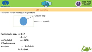
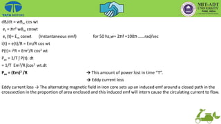
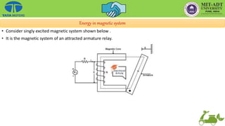
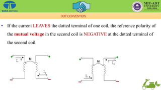
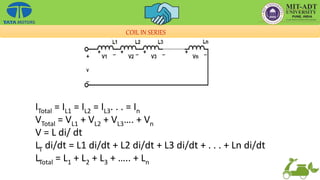
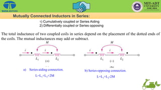
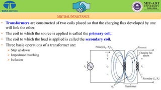
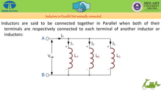
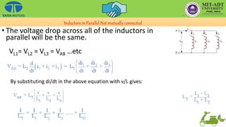
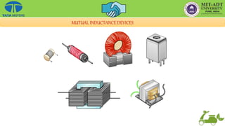
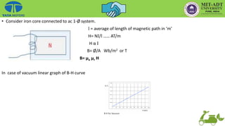
This document provides an overview of the basic principles of electrical machines, including electromagnetic induction, magnetic circuits, inductance, and electromechanical energy conversion. It discusses Faraday's laws of induction, self and mutually induced emf, magnetic circuits, inductance of coils in series and parallel configurations. It also covers concepts of mutual inductance, transformers, hysteresis effects, eddy currents, energy stored in magnetic systems, and the derivation of torque expression based on co-energy.


![Energy Balance equation for motor:
Total electrical i/p = [Total mechanical output ]+ [Total energy stored]+ [Total energy dispatched] _1
Wei = [Wmo ]+[Wes+Wms]+[I2R + Magenetic losses in core + F/w losses]
Wei – ohmic loss = [Wmo+ Wms + Mechanical loss]+ [Wes + loss in coupling
field]
Therefore,
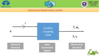
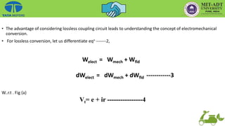
Welect = Wmech + Wfld ____2
Where
Welect = Wei = Net input electrical energy to the coupling field.
Wfld = Energy stored in coupling field
Wmech = Total energy converted from electrical to mechanical
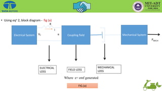
Using eqn 2, block diagram - fig (a)](https://image.slidesharecdn.com/aedcuniti-230108144326-5a8d4816/85/AEDC_Unit-I-pptx-29-320.jpg)
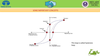
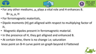
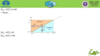
![• There is hysteresis effect in B-H curve.
• Due to partial alignment of dipoles of the increase in the value of H,
dipoles become more and more alinged and reaches to a certain point,
from that point current started reversing.
[Refer point ‘x’ on B-H curve].
ʃ B H d v
• As per faraday’s law ,
• Flux linkage , λ =N Ø
= LI](https://image.slidesharecdn.com/aedcuniti-230108144326-5a8d4816/85/AEDC_Unit-I-pptx-38-320.jpg)
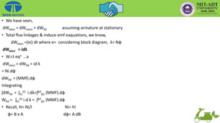
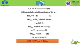
![emf included, e= dλ/dt
= N dØ/dt = L di/d
Vt = e + ir
= ir + L 2di/dE
• As H ↑, B↑
Therefore , H= NI/l
B= µo µr H = µo µr (NI/l)
B= Ø/A
Ø=B.A
= µo µr (N x i x A/l)
= (µo µr A/l) N x I
But λ= NØ
=N [(µo µr A/l) Nx I]
λ= N2 (µo µr A/l) I](https://image.slidesharecdn.com/aedcuniti-230108144326-5a8d4816/85/AEDC_Unit-I-pptx-39-320.jpg)